Spanning Tree Protocol (STP) - Router Alley
Spanning Tree Protocol (STP) - Router Alley
Spanning Tree Protocol (STP) - Router Alley

You also want an ePaper? Increase the reach of your titles
YUMPU automatically turns print PDFs into web optimized ePapers that Google loves.
<strong>Spanning</strong> <strong>Tree</strong> <strong>Protocol</strong> v1.21 – Aaron Balchunas<br />
1<br />
Switching Loops<br />
- <strong>Spanning</strong> <strong>Tree</strong> <strong>Protocol</strong> -<br />
By default, a switch will forward a broadcast or multicast out all ports,<br />
excluding the port the broadcast/multicast was sent from.<br />
When a loop is introduced into the network, a highly destructive broadcast<br />
storm can develop within seconds. Broadcast storms occur when broadcasts<br />
are endlessly switched through the loop, choking off all other traffic.<br />
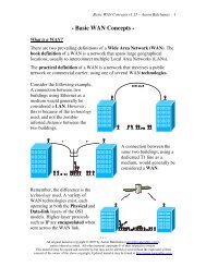
Consider the following looped environment:<br />
Switch 1<br />
Switch 2 Switch 3<br />
Switch 4 Switch 5<br />
If the computer connected to Switch 4 sends out a broadcast, the switch will<br />
forward the broadcast out all ports, including the ports connecting to Switch<br />
2 and Switch 5. Those switches, likewise, will forward that broadcast out all<br />
ports, including to their neighboring switches.<br />
The broadcast will loop around the switches infinitely. In fact, there will be<br />
two separate broadcast storms cycling in opposite directions through the<br />
switching loop. Only powering off the switch or physically removing the<br />
loop will stop the storm.<br />
* * *<br />
All original material copyright © 2009 by Aaron Balchunas (aaron@routeralley.com),<br />
unless otherwise noted. All other material copyright © of their respective owners.<br />
This material may be copied and used freely, but may not be altered or sold without the expressed written<br />
consent of the owner of the above copyright. Updated material may be found at http://www.routeralley.com.
<strong>Spanning</strong> <strong>Tree</strong> <strong>Protocol</strong> v1.21 – Aaron Balchunas<br />
2<br />
<strong>Spanning</strong> <strong>Tree</strong> <strong>Protocol</strong> (<strong>STP</strong>)<br />
Switches (and bridges) needed a mechanism to prevent loops from forming,<br />
and thus <strong>Spanning</strong> <strong>Tree</strong> <strong>Protocol</strong> (<strong>STP</strong>, or IEEE 802.1D) was developed.<br />
<strong>STP</strong> is enabled by default on all VLANs on Catalyst switches.<br />
<strong>STP</strong>-enabled switches communicate to form a topology of the entire<br />
switching network, and then shutting down (or blocking) a port if a loop<br />
exists. The blocked port can be reactivated if another link on the switching<br />
network goes down, thus preserving fault-tolerance. Once all switches agree<br />
on the topology database, the switches are considered converged.<br />
<strong>STP</strong> switches send BPDU’s (Bridge <strong>Protocol</strong> Data Units) to each other to<br />
form their topology databases. BPDU’s are sent out all ports every two<br />
seconds, are forwarded to a specific MAC multicast address:<br />
0180.c200.0000.<br />
<strong>STP</strong> Types<br />
Various flavors of 802.1D <strong>STP</strong> exist, including:<br />
• Common <strong>Spanning</strong> <strong>Tree</strong> (CST) – A single <strong>STP</strong> process is used for<br />
all VLANs.<br />
• Per-VLAN <strong>Spanning</strong> <strong>Tree</strong> (PVST) – Cisco proprietary version of<br />
<strong>STP</strong>, which employs a separate <strong>STP</strong> process for each VLAN.<br />
• Per-VLAN <strong>Spanning</strong> <strong>Tree</strong> Plus (PVST+) – Enhanced version of<br />
PVST that allows CST-enabled switches and PVST-enabled switches<br />
to interoperate. This is default on newer Catalyst switches.<br />
The <strong>STP</strong> Process<br />
To maintain a loop-free environment, <strong>STP</strong> performs the following functions:<br />
• A Root Bridge is elected<br />
• Root Ports are identified<br />
• Designated Ports are identified<br />
• If a loop exists, a port is placed in Blocking state. If the loop is<br />
removed the blocked port is activated again.<br />
If multiple loops exist in the switching environment, multiple ports will be<br />
placed in a blocking state.<br />
* * *<br />
All original material copyright © 2009 by Aaron Balchunas (aaron@routeralley.com),<br />
unless otherwise noted. All other material copyright © of their respective owners.<br />
This material may be copied and used freely, but may not be altered or sold without the expressed written<br />
consent of the owner of the above copyright. Updated material may be found at http://www.routeralley.com.
<strong>Spanning</strong> <strong>Tree</strong> <strong>Protocol</strong> v1.21 – Aaron Balchunas<br />
3<br />
Electing an <strong>STP</strong> Root Bridge<br />
The first step in the <strong>STP</strong> process is electing a Root Bridge, which serves as<br />
the centralized point of the <strong>STP</strong> topology. Good design practice dictates that<br />
the Root Bridge be placed closest to the center of the <strong>STP</strong> topology.<br />
The Root Bridge is determined by a switch’s priority. The default priority is<br />
32,768, and the lowest priority wins. In case of a tie in priority, the switch<br />
with the lowest MAC address will be elected root bridge. The combination<br />
of a switch’s priority and MAC address make up that switch’s Bridge ID.<br />
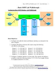
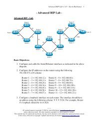
Consider the following example:<br />
Remember that the lowest priority determines the Root Bridge. Switches 2,<br />
3, and 5 have the default priority set. Switches 1 and 4 each have a priority<br />
of 100 configured. However, Switch 1 will become the root bridge, as it has<br />
the lowest MAC address.<br />
Switches exchange BPDU’s to perform the election process. By default, all<br />
switches “believe” they are the Root Bridge, until a switch with a lower<br />
Bridge ID is discovered.<br />
Root Bridge elections are a continuous process. If a new switch with a lower<br />
Bridge ID is added to the topology, it will be elected as the new Root<br />
Bridge.<br />
* * *<br />
All original material copyright © 2009 by Aaron Balchunas (aaron@routeralley.com),<br />
unless otherwise noted. All other material copyright © of their respective owners.<br />
This material may be copied and used freely, but may not be altered or sold without the expressed written<br />
consent of the owner of the above copyright. Updated material may be found at http://www.routeralley.com.
<strong>Spanning</strong> <strong>Tree</strong> <strong>Protocol</strong> v1.21 – Aaron Balchunas<br />
4<br />
Identifying Root Ports<br />
The second step in the <strong>STP</strong> process is identifying Root Ports, or the port on<br />
each switch that has the lowest path cost to get to the Root Bridge. Each<br />
switch has only one Root Port, and the Root Bridge cannot have a Root Port.<br />
Path Cost is a cumulative cost based on the bandwidth of the links. The<br />
higher the bandwidth, the lower the Path Cost:<br />
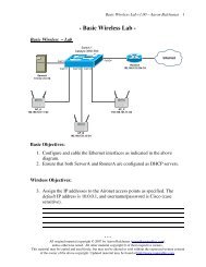
Consider the following example:<br />
Bandwidth Cost<br />
4 Mbps 250<br />
10 Mbps 100<br />
16 Mbps 62<br />
100 Mbps 19<br />
1 Gbps 4<br />
Assume the links between all switches are 10Mbps Ethernet, with a Path<br />
Cost of 100. Each switch will identify the port with the least cumulative Path<br />
Cost to get to the Root Bridge.<br />
For Switch 4, the port leading up to Switch 2 has a Path Cost of 200, and<br />
becomes the Root Port. The port to Switch 5 has a higher Path Cost of 300.<br />
The Root Port is said to have received the most superior BPDU to the Root<br />
Bridge. Likewise, non-Root Ports are said to have received inferior BPDU’s<br />
to the Root Bridge.<br />
* * *<br />
All original material copyright © 2009 by Aaron Balchunas (aaron@routeralley.com),<br />
unless otherwise noted. All other material copyright © of their respective owners.<br />
This material may be copied and used freely, but may not be altered or sold without the expressed written<br />
consent of the owner of the above copyright. Updated material may be found at http://www.routeralley.com.
<strong>Spanning</strong> <strong>Tree</strong> <strong>Protocol</strong> v1.21 – Aaron Balchunas<br />
5<br />
Identifying Designated Ports<br />
The third and final step in the <strong>STP</strong> process is to identify Designated Ports.<br />
Each network segment requires a single Designated Port, which has the<br />
lowest path cost leading to the Root Bridge. This port will not be placed in a<br />
blocking state. A port cannot be both a Designated Port and a Root Port.<br />
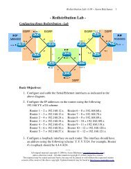
Consider the following example:<br />
Ports on the Root Bridge are never placed in a blocking state, and thus<br />
become Designated Ports for directly attached segments.<br />
The network segments between Switches 2 and 4, and between Switches 3<br />
and 5, both require a Designated Port. The ports on Switch 2 and Switch 3<br />
have the lowest Path Cost to the Root Bridge for the two respective<br />
segments, and thus both become Designated Ports.<br />
The segment between Switch 4 and Switch 5 does not contain a Root Port.<br />
One of the ports must be elected the Designated Port for that segment, and<br />
the other must be placed in a blocking state.<br />
Normally, Path Cost is used to determine which port is blocked. However,<br />
the ports connecting Switches 4 and 5 have the same Path Cost to reach the<br />
Root Bridge (200). Whichever switch has the lowest Bridge ID is awarded<br />
the Designated Port. Whichever switch has the highest Bridge ID has its<br />
port placed in a blocking state. In this example, Switch 4 has the lowest<br />
priority, and thus Switch 5’s port goes into a blocking state.<br />
* * *<br />
All original material copyright © 2009 by Aaron Balchunas (aaron@routeralley.com),<br />
unless otherwise noted. All other material copyright © of their respective owners.<br />
This material may be copied and used freely, but may not be altered or sold without the expressed written<br />
consent of the owner of the above copyright. Updated material may be found at http://www.routeralley.com.
<strong>Spanning</strong> <strong>Tree</strong> <strong>Protocol</strong> v1.21 – Aaron Balchunas<br />
6<br />
Port ID<br />
In certain circumstances, a tie will occur in both Path Cost and Bridge ID.<br />
Consider the following example:<br />
Switch 1<br />
Root Bridge<br />
Fa0/10<br />
Fa0/11<br />
Switch 2<br />
If the bandwidth of both links are equal, then both of Switch 2’s interfaces<br />
have an equal path cost to the Root Bridge. Which interface will become the<br />
Root Port? The tiebreaker should be the lowest Bridge ID, but that cannot be<br />
used in this circumstance (unless Switch 2 has become schizophrenic).<br />
In this circumstance, Port ID will be used as the tiebreaker. An interface’s<br />
Port ID consists of two parts - a 6-bit port priority value, and the MAC<br />
address for that port. Whichever interface has the lowest Port ID will<br />
become the Root Port.<br />
By default, the port priority of an interface is 128. Lowering this value will<br />
ensure a specific interface becomes the Root Port:<br />
Switch(config)# int fa0/10<br />
Switch(config-if)# spanning-tree port-priority 50<br />
Remember, that port priority is the last tiebreaker <strong>STP</strong> will consider. <strong>STP</strong><br />
decides Root and Designated Ports based on the following criteria, and in<br />
this order:<br />
• Lowest Path Cost to the Root Bridge<br />
• Lowest Bridge ID<br />
• Lowest Port ID<br />
* * *<br />
All original material copyright © 2009 by Aaron Balchunas (aaron@routeralley.com),<br />
unless otherwise noted. All other material copyright © of their respective owners.<br />
This material may be copied and used freely, but may not be altered or sold without the expressed written<br />
consent of the owner of the above copyright. Updated material may be found at http://www.routeralley.com.
<strong>Spanning</strong> <strong>Tree</strong> <strong>Protocol</strong> v1.21 – Aaron Balchunas<br />
7<br />
Extended System IDs<br />
Normally, a switch’s Bridge ID is a 64-bit value that consists of a 16-bit<br />
Bridge Priority value, and a 48-bit MAC address.<br />
However, it is possible to include a VLAN ID, called an extended System<br />
ID, into a Bridge ID. Instead of adding bits to the existing Bridge ID, 12 bits<br />
of the Bridge Priority value are used for this System ID, which identifies the<br />
VLAN this <strong>STP</strong> process represents.<br />
Because 12 bits have been stolen from the Bridge Priority field, the range of<br />
priorities has been reduced. Normally, the Bridge Priority can range from 0<br />
(or off) to 65,535, with a default value of 32,768. With extended System ID<br />
enabled, the Priority range would be 0 – 61,440, and only in multiples of<br />
4,096.<br />
To enable the extended System ID:<br />
Switch(config)# spanning-tree extend system-id<br />
Enabling extended System ID accomplishes two things:<br />
• Increases the amount of supported VLANs on the switch from 1005 to<br />
4094.<br />
• Includes the VLAN ID as part of the Bridge ID.<br />
Thus, when this command is enabled, the 64-bit Bridge ID will consist of the<br />
following:<br />
• 4-bit Priority Value<br />
• 12-bit System ID value (VLAN ID)<br />
• 48-bit MAC address<br />
* * *<br />
All original material copyright © 2009 by Aaron Balchunas (aaron@routeralley.com),<br />
unless otherwise noted. All other material copyright © of their respective owners.<br />
This material may be copied and used freely, but may not be altered or sold without the expressed written<br />
consent of the owner of the above copyright. Updated material may be found at http://www.routeralley.com.
<strong>Spanning</strong> <strong>Tree</strong> <strong>Protocol</strong> v1.21 – Aaron Balchunas<br />
8<br />
Per-VLAN <strong>Spanning</strong> <strong>Tree</strong> (PVST) Example<br />
Remember that PVST+ is the default implementation of <strong>STP</strong> on Catalyst<br />
switches. Thus, each VLAN on the switch is allotted its own <strong>STP</strong> process.<br />
Consider the following example:<br />
With Common <strong>Spanning</strong> <strong>Tree</strong> (CST), all VLANS would belong to the same<br />
<strong>STP</strong> process. Thus, if one Switch 4’s ports entered a blocking state to<br />
eliminate the loop, all VLANs would be blocked out that port. For efficiency<br />
purposes, this may not be ideal.<br />
In the above examples, the benefit of PVST becomes apparent. <strong>STP</strong> runs a<br />
separate process for each VLAN, allowing a port to enter a blocking state<br />
only for that specific VLAN. Thus, it is possible to load balance VLANs,<br />
allowing traffic to flow more efficiently.<br />
* * *<br />
All original material copyright © 2009 by Aaron Balchunas (aaron@routeralley.com),<br />
unless otherwise noted. All other material copyright © of their respective owners.<br />
This material may be copied and used freely, but may not be altered or sold without the expressed written<br />
consent of the owner of the above copyright. Updated material may be found at http://www.routeralley.com.
<strong>Spanning</strong> <strong>Tree</strong> <strong>Protocol</strong> v1.21 – Aaron Balchunas<br />
9<br />
<strong>STP</strong> Port States<br />
Switch ports participating in <strong>STP</strong> progress through five port states:<br />
Blocking – The default state of an <strong>STP</strong> port when a switch is powered on,<br />
and when a port is shut down to eliminate a loop. Ports in a blocking state do<br />
not forward frames or learn MAC addresses. It will still listen for BPDUs<br />
from other switches, to learn about changes to the switching topology.<br />
Listening – A port will progress from a Blocking to a Listening state only if<br />
the switch believes that the port will not be shut down to eliminate a loop.<br />
The port will listen for BPDU’s to participate in the election of a Root<br />
Bridge, Root Ports, and Designated Ports. Ports in a listening state will not<br />
forward frames or learn MAC addresses.<br />
Learning – After a brief period of time, called a Forward Delay, a port in a<br />
listening state will be elected either a Root Port or Designated Port, and<br />
placed in a learning state. Ports in a learning state listen for BPDUs, and also<br />
begin to learn MAC addresses. However, ports in a learning state will still<br />
not forward frames.<br />
(Note: If a port in a listening state is not kept as a Root or a Designated Port,<br />
it will be placed into a blocking state and not a learning state.)<br />
Forwarding – After another Forward Delay, a port in learning mode will be<br />
placed in forwarding mode. Ports in a forwarding state can send and receive<br />
all data frames, and continue to build the MAC address table. All designated,<br />
root, and non-uplink ports will eventually be placed in a forwarding state.<br />
Disabled – A port in disabled state has been administratively shut down, and<br />
does not participate in <strong>STP</strong> or forward frames at all.<br />
On average, a port in a blocking state will take 30 to 50 seconds to reach a<br />
forwarding state.<br />
To view the current state of a port (such fa0/10):<br />
Switch# show spanning-tree interface fa0/10<br />
Interface Fa0/10 in <strong>Spanning</strong> tree 1 is Forwarding<br />
Port path cost 100, Port priority 128<br />
<br />
(Reference: http://www.cisco.com/en/US/docs/switches/lan/catalyst4500/12.1/8aew/configuration/guide/spantree.html#wp1020487)<br />
* * *<br />
All original material copyright © 2009 by Aaron Balchunas (aaron@routeralley.com),<br />
unless otherwise noted. All other material copyright © of their respective owners.<br />
This material may be copied and used freely, but may not be altered or sold without the expressed written<br />
consent of the owner of the above copyright. Updated material may be found at http://www.routeralley.com.
<strong>Spanning</strong> <strong>Tree</strong> <strong>Protocol</strong> v1.21 – Aaron Balchunas<br />
10<br />
<strong>STP</strong> Timers<br />
<strong>STP</strong> utilizes three timers to ensure all switches remain synchronized, and to<br />
allow enough time for the <strong>Spanning</strong> <strong>Tree</strong> process to ensure a loop-free<br />
environment.<br />
• Hello Timer – Default is 2 seconds. Indicates how often BPDU’s are<br />
sent by switches.<br />
• Forward Delay – Default is 15 seconds. Indicates a delay period in<br />
both the listening and learning states of a port, for a total of 30<br />
seconds. This delay ensures <strong>STP</strong> has ample time to detect and<br />
eliminate loops.<br />
• Max Age – Default is 20 seconds. Indicates how long a switch will<br />
keep BPDU information from a neighboring switch before discarding<br />
it. In other words, if a switch fails to receive BPDU’s from a<br />
neighboring switch for the Max Age period, it will remove that<br />
switch’s information from the <strong>STP</strong> topology database.<br />
All timer values can be adjusted, and should only be adjusted on the Root<br />
Bridge. The Root Bridge will propagate the changed timers to all other<br />
switches participating in <strong>STP</strong>. Non-Root switches will ignore their locally<br />
configured timers.<br />
To adjust the three <strong>STP</strong> timers for VLAN 10:<br />
Switch(config)# spanning-tree vlan 10 hello-time 10<br />
Switch(config)# spanning-tree vlan 10 forward-time 20<br />
Switch(config)# spanning-tree vlan 10 max-age 40<br />
The timers are measured in seconds. The above examples represent the<br />
maximum value each timer can be configured to.<br />
Remember that <strong>STP</strong> is configured on a VLAN by VLAN basis on Catalyst<br />
Switches.<br />
* * *<br />
All original material copyright © 2009 by Aaron Balchunas (aaron@routeralley.com),<br />
unless otherwise noted. All other material copyright © of their respective owners.<br />
This material may be copied and used freely, but may not be altered or sold without the expressed written<br />
consent of the owner of the above copyright. Updated material may be found at http://www.routeralley.com.
<strong>Spanning</strong> <strong>Tree</strong> <strong>Protocol</strong> v1.21 – Aaron Balchunas<br />
11<br />
<strong>STP</strong> Topology Changes<br />
Switch 1<br />
Root Bridge<br />
Root Port<br />
Root Port<br />
Switch 2 Switch 3<br />
Root Port<br />
Root Port<br />
Switch 4 Switch 5<br />
An <strong>STP</strong> topology change will occur under two circumstances:<br />
• When an interface is placed into a Forwarding state.<br />
• When an interface already in a Forwarding or Learning state is placed<br />
into a Blocking state.<br />
The switch recognizing this topology change will send out a TCN<br />
(Topology Change Notification) BPDU, destined for the Root Bridge. The<br />
TCN BPDU does not contain any data about the actual change – it only<br />
indicates that a change occurred.<br />
For example, if the interface on Switch 4 connecting to Switch 5 went down,<br />
Switch 4 would send a TCN out its Root Port to Switch 2. Switch 2 will<br />
acknowledge this TCN by sending a BPDU back to Switch 4 with the<br />
Topology Change Acknowledgement (TCA) bit set. Switch 2 would then<br />
forward the TCN out its Root Port to Switch 1 (the Root Bridge).<br />
Once the Root Bridge receives the TCN, it will send out a BPDU with the<br />
Topology Change (TC) bit set to all switches. When a switch receives this<br />
Root BPDU, it will temporarily lower its MAC-address Aging Timer from<br />
300 seconds to 15 seconds, so that any erroneous MAC addresses can be<br />
quickly flushed out of the CAM table.<br />
The MAC-Address Aging Timer will stay lowered to 15 seconds for a<br />
period of 35 seconds by default, or one Max Age (20 seconds) plus one<br />
Forward Delay (15 seconds) timer.<br />
(Reference: http://www.cisco.com/en/US/tech/tk389/tk621/technologies_tech_note09186a0080094797.shtml)<br />
* * *<br />
All original material copyright © 2009 by Aaron Balchunas (aaron@routeralley.com),<br />
unless otherwise noted. All other material copyright © of their respective owners.<br />
This material may be copied and used freely, but may not be altered or sold without the expressed written<br />
consent of the owner of the above copyright. Updated material may be found at http://www.routeralley.com.
<strong>Spanning</strong> <strong>Tree</strong> <strong>Protocol</strong> v1.21 – Aaron Balchunas<br />
12<br />
Basic <strong>STP</strong> Configuration<br />
To disable <strong>STP</strong> for a specific VLAN:<br />
Switch(config)# no spanning-tree vlan 10<br />
To adjust the Bridge Priority of a switch from its default of 32,768, to<br />
increase its chances of being elected Root Bridge of a VLAN:<br />
Switch(config)# spanning-tree vlan 10 priority 150<br />
To change an interface’s Path Cost from its defaults:<br />
Switch(config)# int fa0/24<br />
Switch(config-if)# spanning-tree cost 42<br />
To force a switch to become the Root Bridge:<br />
Switch(config)# spanning-tree vlan 10 root primary<br />
The root primary parameter in the above command automatically lowers the<br />
switch’s priority to 24,576. If another switch on the network has a lower<br />
priority than 24,576, the above command will lower the priority by 4096 less<br />
than the priority of the other switch.<br />
It is possible to assign a Secondary Root Bridge for redundancy. To force a<br />
switch to become a Secondary Root Bridge:<br />
Switch(config)# spanning-tree vlan 10 root secondary<br />
The root secondary parameter in the above command automatically lowers<br />
the switch’s priority to 28,672.<br />
To specify the diameter of the switching topology:<br />
Switch(config)# spanning-tree vlan 10 root primary diameter 7<br />
The diameter parameter in the preceding command indicates the length of<br />
the <strong>STP</strong> topology (number of switches). The maximum (and default) value<br />
for the diameter is 7. Note that the switching topology can contain more than<br />
seven switches; however, each branch of the switching tree can only extend<br />
seven switches deep, from the Root Bridge.<br />
The diameter command will also adjust the Hello, Forward Delay, and Max<br />
Age timers. This is the recommended way to adjust timers, as the hello<br />
timers are tuned specifically to the diameter of the switching network.<br />
* * *<br />
All original material copyright © 2009 by Aaron Balchunas (aaron@routeralley.com),<br />
unless otherwise noted. All other material copyright © of their respective owners.<br />
This material may be copied and used freely, but may not be altered or sold without the expressed written<br />
consent of the owner of the above copyright. Updated material may be found at http://www.routeralley.com.
<strong>Spanning</strong> <strong>Tree</strong> <strong>Protocol</strong> v1.21 – Aaron Balchunas<br />
13<br />
<strong>STP</strong> PortFast<br />
PortFast allows switch ports that connect a host device (such as a printer or<br />
a workstation), to bypass the usual progression of <strong>STP</strong> states. Theoretically,<br />
a port connecting to a host device can never create a switching loop. Thus,<br />
Port Fast allows the interface to move from a blocking state to a forwarding<br />
state immediately, eliminating the normal 30 second <strong>STP</strong> delay.<br />
To configure PortFast on an interface:<br />
Switch(config)# int fa0/10<br />
Switch(config-if)# spanning-tree portfast<br />
To enable PortFast globally on all interfaces:<br />
Switch(config)# spanning-tree portfast default<br />
PortFast should not be enabled on switch ports connecting to another<br />
hub/switch, as this may result in a loop. Note that PortFast does not disable<br />
<strong>STP</strong> on an interface - it merely speeds up the convergence.<br />
PortFast additionally reduces unnecessary BPDU traffic, as TCN BPDU’s<br />
will not be sent out for state changes on a PortFast-enabled interface.<br />
<strong>STP</strong> UplinkFast<br />
Switches can have multiple uplinks to other upstream switches. If the<br />
multiple links are not placed in an EtherChannel, then at least one of the<br />
ports is placed into a blocking state to eliminate the loop.<br />
If a directly-connected interface goes down, <strong>STP</strong> needs to perform a<br />
recalculation to bring the other interface out of a blocking state. As stated<br />
earlier, this calculation can take from 30 to 50 seconds.<br />
UplinkFast allows the port in a blocking state to be held in standby-mode,<br />
and activated immediately if the forwarding interface fails. If multiple ports<br />
are in a blocking state, whichever port has the lowest Root Path Cost will<br />
become unblocked. The Root Bridge cannot have UplinkFast enabled.<br />
UplinkFast is configured globally for all VLANs on the switch:<br />
Switch(config)# spanning-tree uplinkfast<br />
(Reference: http://www.cisco.com/en/US/docs/switches/lan/catalyst3750/software/release/12.2_35_se/configuration/guide/swstpopt.html)<br />
* * *<br />
All original material copyright © 2009 by Aaron Balchunas (aaron@routeralley.com),<br />
unless otherwise noted. All other material copyright © of their respective owners.<br />
This material may be copied and used freely, but may not be altered or sold without the expressed written<br />
consent of the owner of the above copyright. Updated material may be found at http://www.routeralley.com.
<strong>Spanning</strong> <strong>Tree</strong> <strong>Protocol</strong> v1.21 – Aaron Balchunas<br />
14<br />
<strong>STP</strong> BackboneFast<br />
While UplinkFast allows faster convergence if a directly-connected interface<br />
fails, BackboneFast provides the same benefit is an indirectly-connected<br />
interface fails.<br />
For example, if the Root Bridge fails, another switch will be elected the<br />
Root. A switch learning about the new Root Bridge must wait its Max Age<br />
timer to flush out the old information, before it will accept the updated info.<br />
By default, the Max Age timer is 20 seconds.<br />
BackboneFast allows a switch to bypass the Max Age timer if it detects an<br />
indirect failure on the network. It will update itself with the new Root info<br />
immediately.<br />
BackboneFast is configured globally, and should be implemented on all<br />
switches in the network when used:<br />
Switch(config)# spanning-tree backbonefast<br />
Protecting <strong>STP</strong><br />
<strong>STP</strong> is vulnerable to attack for two reasons:<br />
• <strong>STP</strong> builds its topology information by accepting a neighboring<br />
switch’s BPDU’s.<br />
• The Root Bridge is always determined by the lowest Bridge ID.<br />
Switches with a low priority can be maliciously placed on the network, and<br />
elected the Root Bridge. This may result in a suboptimal or unstable <strong>STP</strong><br />
topology.<br />
Cisco implemented three mechanisms to protect the <strong>STP</strong> topology:<br />
• Root Guard<br />
• BPDU Guard<br />
• BPDU Filtering<br />
All three mechanisms are configured on an individual interface basis, and<br />
are disabled by default. When enabled, these mechanisms apply to all<br />
VLANs for that particular interface.<br />
(Reference: http://www.cisco.com/en/US/docs/switches/lan/catalyst3750/software/release/12.2_35_se/configuration/guide/swstpopt.html)<br />
* * *<br />
All original material copyright © 2009 by Aaron Balchunas (aaron@routeralley.com),<br />
unless otherwise noted. All other material copyright © of their respective owners.<br />
This material may be copied and used freely, but may not be altered or sold without the expressed written<br />
consent of the owner of the above copyright. Updated material may be found at http://www.routeralley.com.
<strong>Spanning</strong> <strong>Tree</strong> <strong>Protocol</strong> v1.21 – Aaron Balchunas<br />
15<br />
Root Guard<br />
Root Guard prevents an unauthorized switch from advertising itself as a<br />
Root Bridge.<br />
Switch(config)# interface fa0/10<br />
Switch(config-if)# spanning-tree guard root<br />
The above command will prevents the switch from accepting a new Root<br />
Bridge off of the fa0/10 interface. If a Root Bridge advertises itself to this<br />
port, the port will enter a root-inconsistent state (a pseudo-blocking state):<br />
Switch# show spanning-tree inconsistentports<br />
Name Interface Inconsistency<br />
-------------------- -------------------- ------------------<br />
VLAN100 FastEthernet0/10 Root Inconsistent<br />
BPDU Guard and BPDU Filtering<br />
BPDU Guard is employed on interfaces that are PortFast-enabled. Under<br />
normal circumstances, a PortFast-enabled interface connects to a host<br />
device, and thus the interface should never receive a BPDU.<br />
If another switch is accidentally or maliciously connected into a PortFast<br />
interface, BPDU Guard will place the interface into an errdisable state.<br />
More accurately, if an interface configured for BPDU Guard receives a<br />
BPDU, then the errdisable state will occur. To enable BPDU Guard:<br />
Switch(config)# interface fa0/10<br />
Switch(config-if)# spanning-tree bpduguard enable<br />
To take an interface out of an errdisable state, simply disable and re-enable<br />
the interface:<br />
Switch(config)# interface fa0/10<br />
Switch(config-if)# shutdown<br />
Switch(config-if)# no shutdown<br />
BPDU Filtering essentially disables <strong>STP</strong> on a particular interface, by<br />
preventing it from sending or receiving BPDU’s:<br />
Switch(config)# interface fa0/10<br />
Switch(config-if)# spanning-tree bpdufilter enable<br />
* * *<br />
All original material copyright © 2009 by Aaron Balchunas (aaron@routeralley.com),<br />
unless otherwise noted. All other material copyright © of their respective owners.<br />
This material may be copied and used freely, but may not be altered or sold without the expressed written<br />
consent of the owner of the above copyright. Updated material may be found at http://www.routeralley.com.
<strong>Spanning</strong> <strong>Tree</strong> <strong>Protocol</strong> v1.21 – Aaron Balchunas<br />
16<br />
Unidirectional Link Detection (UDLD)<br />
Most communication in a switching network is bi-directional. <strong>STP</strong> requires<br />
that switches send BPDU’s bi-directionally to build the topology database. If<br />
a malfunctioning switch port only allows traffic one way, and the switch still<br />
sees that port as up, a loop can form without the switch realizing it.<br />
Unidirectional Link Detection (UDLD) periodically tests ports to ensure<br />
bi-directional communication is maintained. UDLD sends out ID frames on<br />
a port, and waits for the remote switch to respond with its own ID frame. If<br />
the remote switch does not respond, UDLD assumes the interface has<br />
malfunctioned and become unidirectional.<br />
By default, UDLD sends out ID frames every 15 seconds, and must be<br />
enabled on both sides of a link. UDLD can run in two modes:<br />
• Normal Mode – If a unidirectional link is detected, the port is not<br />
shut down, but merely flagged as being in an undetermined state<br />
• Aggressive Mode – If a unidirectional link is detected, the port is<br />
placed in an errdisable state<br />
UDLD can be enabled globally (but only for Fiber ports on the switch):<br />
Switch(config)# udld enable message time 20<br />
Switch(config)# udld aggressive message time 20<br />
The enable parameter sets UDLD into normal mode, and the aggressive<br />
parameter is for aggressive mode (obviously). The message time parameter<br />
modifies how often ID frames are sent out.<br />
UDLD can be configured on individual interfaces:<br />
Switch(config-if)# udld enable<br />
Switch(config-if)# udld aggressive<br />
Switch(config-if)# udld disable<br />
To view UDLD status on ports, or re-enable UDLD errdisabled ports:<br />
Switch# show udld<br />
Switch# udld reset<br />
* * *<br />
All original material copyright © 2009 by Aaron Balchunas (aaron@routeralley.com),<br />
unless otherwise noted. All other material copyright © of their respective owners.<br />
This material may be copied and used freely, but may not be altered or sold without the expressed written<br />
consent of the owner of the above copyright. Updated material may be found at http://www.routeralley.com.
<strong>Spanning</strong> <strong>Tree</strong> <strong>Protocol</strong> v1.21 – Aaron Balchunas<br />
17<br />
<strong>STP</strong> Troubleshooting Commands<br />
To view <strong>STP</strong> information for a specific VLAN:<br />
Switch# show spanning-tree vlan 100<br />
VLAN0100<br />
<strong>Spanning</strong> tree enabled protocol ieee<br />
Root ID Priority 24576<br />
Address 00a.5678.90ab<br />
Cost 19<br />
Port 24 (FastEthernet0/24)<br />
Hello Time 2 sec Max Age 20 sec Forward Delay 15 sec<br />
Bridge ID Priority 32768 (priority 32768 sys-id-ext 1)<br />
Address 000c.1234.abcd<br />
Hello Time 2 sec Max Age 20 sec Forward Delay 15 sec<br />
Aging Time 300<br />
Interface Role Sts Cost Prio.Nbr<br />
----------------- --- ----- ----------- ----------------<br />
Fa0/24 Root FWD 19 128.24<br />
Fa0/23 Altn BLK 19 128.23<br />
To view <strong>STP</strong> information for all VLANS:<br />
Switch# show spanning-tree<br />
To view detailed <strong>STP</strong> interface information:<br />
Switch# show spanning-tree detail<br />
VLAN100 is executing the ieee compatible <strong>Spanning</strong> <strong>Tree</strong> protocol<br />
Bridge Identifier has priority 32768, address 000c.1234.abcd<br />
Configured hello time 2, max age 20, forward delay 15<br />
<br />
Port 23 (FastEthernet0/23) of VLAN100 is forwarding<br />
Port path cost 19, Port priority 128, Port Identifier 128.23.<br />
Designated root has priority 24576, address 00a.5678.90ab<br />
Designated bridge has priority 24576, address 00a.5678.90ab<br />
Designated port id is 128.23, designated path cost 0<br />
<br />
(Reference: http://www.cisco.com/en/US/docs/switches/lan/catalyst6500/ios/12.1E/native/command/reference/show4.html#wp1026768)<br />
* * *<br />
All original material copyright © 2009 by Aaron Balchunas (aaron@routeralley.com),<br />
unless otherwise noted. All other material copyright © of their respective owners.<br />
This material may be copied and used freely, but may not be altered or sold without the expressed written<br />
consent of the owner of the above copyright. Updated material may be found at http://www.routeralley.com.
<strong>Spanning</strong> <strong>Tree</strong> <strong>Protocol</strong> v1.21 – Aaron Balchunas<br />
18<br />
Rapid <strong>Spanning</strong> <strong>Tree</strong> <strong>Protocol</strong> (R<strong>STP</strong>)<br />
To further alleviate the 30 to 50 second convergence delays with <strong>STP</strong>,<br />
enhancements were made to the original IEEE 802.1D standard. The result<br />
was 802.1w, or Rapid <strong>Spanning</strong> <strong>Tree</strong> <strong>Protocol</strong> (R<strong>STP</strong>).<br />
R<strong>STP</strong> is similar in many respects to <strong>STP</strong>. BPDU’s are forwarded between<br />
switches, and a Root Bridge is elected, based on the lowest Bridge ID. Root<br />
Ports and Designated Ports are also elected. R<strong>STP</strong> defines five port types:<br />
• Root Port – Switch port on each switch that has the best Path Cost to<br />
the Root Bridge (same as <strong>STP</strong>).<br />
• Alternate Port – A backup Root Port, that has a less desirable Path<br />
Cost. An Alternate Port is placed in a discarding state.<br />
• Designated Port – Non-Root port that represents the best Path Cost<br />
for each network segment to the Root Bridge (same as <strong>STP</strong>).<br />
Designated ports are also referred to as Point-to-Point ports.<br />
• Backup Port – A backup Designated Port, that has a less desirable<br />
Path Cost. A Backup Port is placed in a discarding state.<br />
• Edge Port – A port connecting a host device, which is moved to a<br />
Forwarding state immediately. If an Edge Port receives a BPDU, it<br />
will lose its Edge Port status and participate in R<strong>STP</strong> calculations. On<br />
Cisco Catalyst switches, any port configured with PortFast becomes<br />
an Edge Port.<br />
The key benefit of R<strong>STP</strong> is speedier convergence. Switches no longer<br />
require artificial Forwarding Delay timers to ensure a loop-free environment.<br />
Switches instead perform a handshake synchronization to ensure a<br />
consistent topology table. During initial convergence, the Root Bridge and<br />
its directly-connected switches will place their interfaces in a discarding<br />
state. The Root Bridge and those switches will exchange BPDU’s,<br />
synchronize their topology tables, and then place their interfaces in a<br />
forwarding state.<br />
Each switch will then perform the same handshaking process with their<br />
downstream neighbors. The result is convergence that completes in a few<br />
seconds, as opposed to 30 to 50 seconds.<br />
(Reference: http://www.cisco.com/en/US/tech/tk389/tk621/technologies_white_paper09186a0080094cfa.shtml)<br />
* * *<br />
All original material copyright © 2009 by Aaron Balchunas (aaron@routeralley.com),<br />
unless otherwise noted. All other material copyright © of their respective owners.<br />
This material may be copied and used freely, but may not be altered or sold without the expressed written<br />
consent of the owner of the above copyright. Updated material may be found at http://www.routeralley.com.
<strong>Spanning</strong> <strong>Tree</strong> <strong>Protocol</strong> v1.21 – Aaron Balchunas<br />
19<br />
Rapid <strong>Spanning</strong> <strong>Tree</strong> <strong>Protocol</strong> (R<strong>STP</strong>) (continued)<br />
Changes to the R<strong>STP</strong> topology are also handled more efficiently than<br />
802.1D <strong>STP</strong>.<br />
Recall in that in 802.1D <strong>STP</strong>, a switch recognizing a topology change will<br />
send out a TCN (Topology Change Notification) BPDU, destined for the<br />
Root Bridge. Once the Root Bridge receives the TCN, it will send out a<br />
BPDU with the Topology Change (TC) bit set to all switches. When a<br />
switch receives this Root BPDU, it will temporarily lower its MAC-address<br />
Aging Timer from 300 seconds to 15 seconds, so that any erroneous MAC<br />
addresses can be quickly flushed out of the CAM table.<br />
In R<strong>STP</strong>, a switch recognizing a topology change does not have to inform<br />
the Root Bridge first. Any switch can generate and forward a TC BPDU. A<br />
switch receiving a TC BPDU will flush all MAC addresses learned on all<br />
ports, except for the port that received the TC BPDU.<br />
R<strong>STP</strong> incorporates the features of UplinkFast by allowing Alternate and<br />
Backup ports to immediately enter a Forwarding state, if the primary Root or<br />
Designated port fails. R<strong>STP</strong> also inherently employs the principles of<br />
BackboneFast, by not requiring an arbitrary Max Age timer for accepting<br />
inferior BPDU’s if there is an indirect network failure.<br />
802.1w R<strong>STP</strong> is backwards-compatible with 802.1D <strong>STP</strong>. However, when<br />
R<strong>STP</strong> switches interact with <strong>STP</strong> switches, R<strong>STP</strong> loses its inherent<br />
advantages, as will perform according to 802.1D specifications.<br />
Two separate standards of R<strong>STP</strong> have been developed:<br />
• Rapid Per-VLAN <strong>Spanning</strong> <strong>Tree</strong> <strong>Protocol</strong> (RPVST+) – Cisco’s<br />
proprietary implementation of R<strong>STP</strong>.<br />
• Multiple <strong>Spanning</strong> <strong>Tree</strong> (MST) – The IEEE 802.1s standard or<br />
R<strong>STP</strong>.<br />
(Reference: http://www.cisco.com/en/US/tech/tk389/tk621/technologies_white_paper09186a0080094cfa.shtml)<br />
* * *<br />
All original material copyright © 2009 by Aaron Balchunas (aaron@routeralley.com),<br />
unless otherwise noted. All other material copyright © of their respective owners.<br />
This material may be copied and used freely, but may not be altered or sold without the expressed written<br />
consent of the owner of the above copyright. Updated material may be found at http://www.routeralley.com.
<strong>Spanning</strong> <strong>Tree</strong> <strong>Protocol</strong> v1.21 – Aaron Balchunas<br />
20<br />
Multiple <strong>Spanning</strong> <strong>Tree</strong> (MST)<br />
Earlier in this guide, two types of <strong>STP</strong> were defined:<br />
• Common <strong>Spanning</strong> <strong>Tree</strong> (CST) – All VLANs utilize one <strong>STP</strong><br />
process<br />
• Per-VLAN <strong>Spanning</strong> <strong>Tree</strong> (PVST) – Each VLAN is allotted its own<br />
<strong>STP</strong> process<br />
PVST allows for more efficient traffic flow throughout the switching<br />
network. However, each VLAN must run its own separate <strong>STP</strong> process,<br />
often placing an extreme burden on the switch’s processor.<br />
Multiple <strong>Spanning</strong> <strong>Tree</strong> (MST) allows groups of VLANs to be allotted<br />
their own <strong>STP</strong> process. Each <strong>STP</strong> process is called an instance. MST<br />
separates the <strong>STP</strong> topology into regions that must contain identical<br />
parameters, including:<br />
• Configuration Name - a 32-bit value similar to a VTP domain<br />
• Revision Number – a 16-bit value that identifies the current MST<br />
configuration’s revision.<br />
• VLAN-to-Instance Mappings<br />
Each region runs its own Internal <strong>Spanning</strong> <strong>Tree</strong> (IST) to eliminate loops<br />
within that region. IST is essentially an enhanced form of R<strong>STP</strong> that<br />
supports MST-specific parameters.<br />
MST is fully compatible with all other implementations of <strong>STP</strong>.<br />
(Reference: http://www.cisco.com/en/US/docs/switches/lan/catalyst4500/12.2/31sg/configuration/guide/spantree.pdf)<br />
* * *<br />
All original material copyright © 2009 by Aaron Balchunas (aaron@routeralley.com),<br />
unless otherwise noted. All other material copyright © of their respective owners.<br />
This material may be copied and used freely, but may not be altered or sold without the expressed written<br />
consent of the owner of the above copyright. Updated material may be found at http://www.routeralley.com.
<strong>Spanning</strong> <strong>Tree</strong> <strong>Protocol</strong> v1.21 – Aaron Balchunas<br />
21<br />
MST Configuration<br />
MST must first be enabled globally on a switch:<br />
Switch(config)# spanning-tree mode mst<br />
Most other MST configuration is completed in “MST Configuration” mode:<br />
Switch(config)# spanning-tree mst configuration<br />
To configure the switch’s MST Configuration Name:<br />
Switch(config-mst)# name MYMSTNAME<br />
To configure the switch’s Revision Number:<br />
Switch(config-mst)# revision 10<br />
To map VLANs to a specific MST instance:<br />
Switch(config-mst)# instance 2 vlan 1-100<br />
A maximum of 16 instances are allowed (0 – 15). By default, all VLANs<br />
belong to instance 0. Recall that the above three parameters (configuration<br />
name, revision number, and mappings) must be identical on all MST<br />
switches in a region.<br />
To view the changes to the configuration:<br />
Switch(config-mst)# show pending<br />
Pending MST configuration<br />
Name [MYMSTNAME]<br />
Revision 10<br />
Instance Vlans mapped<br />
-------- -------------------------------------------------<br />
0 101-4094<br />
2 1-100<br />
All other configuration of MST is identical to standard <strong>STP</strong>, with two<br />
exceptions. The parameter “mst” must be used, and all settings are applied<br />
to instances instead of VLANs.<br />
Switch(config)# spanning-tree mst 2 root primary<br />
Switch(config)# spanning-tree mst 2 priority 32000<br />
The above two configurations are applied to MST Instance 2.<br />
* * *<br />
All original material copyright © 2009 by Aaron Balchunas (aaron@routeralley.com),<br />
unless otherwise noted. All other material copyright © of their respective owners.<br />
This material may be copied and used freely, but may not be altered or sold without the expressed written<br />
consent of the owner of the above copyright. Updated material may be found at http://www.routeralley.com.