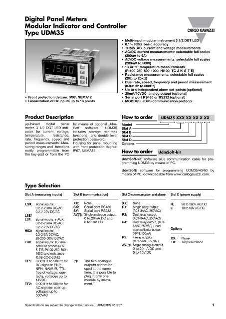
Digital Panel Meters Modular Indicator and Controller Type UDM35
Digital Panel Meters Modular Indicator and Controller Type UDM35
Digital Panel Meters Modular Indicator and Controller Type UDM35

Create successful ePaper yourself
Turn your PDF publications into a flip-book with our unique Google optimized e-Paper software.
<strong>Digital</strong> <strong>Panel</strong> <strong>Meters</strong><br />
<strong>Modular</strong> <strong>Indicator</strong> <strong>and</strong> <strong>Controller</strong><br />
<strong>Type</strong> <strong>UDM35</strong><br />
• Front protection degree: IP67, NEMA12<br />
• Linearization of Hz inputs up to 16 points<br />
• Multi-input modular instrument 3 1/2 DGT LED<br />
• 0.1% RDG basic accuracy<br />
• TRMS AC current <strong>and</strong> voltage measurements<br />
• AC/DC current measurements: selectable full scales<br />
(200µA to 5A)<br />
• AC/DC voltage measurements: selectable full scales<br />
(200mV to 500V)<br />
• °C or °F temperature measurements<br />
(Pt100-250-500-1000, Ni100, TC J-K-S-T-E)<br />
• Resistance measurements: selectable full scales<br />
(20Ω to 20kΩ)<br />
• Dual rate, speed, frequency <strong>and</strong> period measurement<br />
(0.001Hz to 50kHz)<br />
• Up to 4 independent alarm set-points (optional)<br />
• 20mA/10VDC analog output (optional)<br />
• Serial port RS485 or RS232 (optional)<br />
• MODBUS, JBUS communication protocol<br />
Product Description<br />
µp-based digital panel<br />
meter, 3 1/2 DGT LED indicator,<br />
for current, voltage,<br />
temperature, resistance,<br />
rate, frequency, speed <strong>and</strong><br />
period measurements. Measuring<br />
ranges <strong>and</strong> functions<br />
easily programmable from<br />
the key-pad or from the PC<br />
by means of optional Udm-<br />
Soft software. <strong>UDM35</strong><br />
includes storage min-max<br />
functions <strong>and</strong> double level<br />
protection password.<br />
Housing for panel mounting<br />
with front protection degree:<br />
IP67, NEMA12.<br />
How to order<br />
Model<br />
Slot A<br />
Slot B<br />
Slot C<br />
Slot D<br />
Options<br />
How to order<br />
<strong>UDM35</strong> XXX XX XX X XX<br />
UdmSoft-kit<br />
UdmSoft-kit: software plus communication cable for programming<br />
<strong>UDM35</strong> by means of PC.<br />
UdmSoft: software for programming <strong>UDM35</strong>/40/60 by<br />
means of PC, downloadable from www.carlogavazzi.com.<br />
<strong>Type</strong> Selection<br />
Slot A (measuring inputs)<br />
Slot B (communication)<br />
Slot C (communication <strong>and</strong> alarm)<br />
Slot D (power supply)<br />
LSX:<br />
LSE/<br />
LSF:<br />
HSX:<br />
TRX:<br />
TF1:<br />
TF2:<br />
signal inputs:<br />
0.2-2-20mA DC/AC;<br />
0.2-2-20V DC/AC<br />
signal inputs: + AUX:<br />
0.2-2-20mA DC/AC;<br />
0.2-2-20V DC/AC<br />
signal inputs:<br />
0.2-2-5A DC/AC;<br />
20-200-500V DC/AC<br />
signal inputs: TC temperature<br />
probes (J-K-<br />
S-T-E, Pt100-250-500-<br />
1000) <strong>and</strong> resistance<br />
(0.02-0.2-2-20kΩ)<br />
0.001Hz to 50kHz for<br />
DC signals: PNP,<br />
NPN, NAMUR, TTL,<br />
free of voltage, contacts,<br />
voltages up to<br />
14VDC<br />
0.001Hz to 50kHz for<br />
AC signals: pick-up,<br />
voltages up to<br />
500VAC<br />
XX: None<br />
SX: Serial port RS485<br />
SY: Serial port RS232<br />
AV(*): Single analogue output,<br />
0 to 20mA DC <strong>and</strong><br />
0 to 10V DC<br />
(*): The two analogue<br />
outputs cannot be<br />
used at the same<br />
time. It is possible to<br />
plug in only one<br />
module by instrument.<br />
XX: None<br />
R1: Single relay output,<br />
(AC1-8AAC, 250VAC)<br />
R2: Dual relay output,<br />
(AC1-8AAC, 250VAC)<br />
R4: Dual relay output, (AC1-<br />
8AAC, 250VAC) + dual<br />
open collector output<br />
(NPN, 100mA)<br />
R5: 4 relay outputs<br />
(AC1-5AAC, 250VAC)<br />
AV(*): Single analogue output,<br />
0 to 20mA DC <strong>and</strong><br />
0 to 10V DC<br />
H: 90 to 260V AC/DC<br />
L: 18 to 60V AC/DC<br />
Options<br />
XX:<br />
TX:<br />
None<br />
Tropicalization<br />
Specifications are subject to change without notice <strong>UDM35</strong>DS 061207 1
<strong>UDM35</strong><br />
Input specifications<br />
Analogue inputs<br />
BQ LSX module<br />
BQ LSE/LSF module<br />
BQ HSX module<br />
BQ TRX module<br />
BQ TRX module<br />
BQTF1 module<br />
BQTF2 module<br />
<strong>Digital</strong> inputs<br />
Number of inputs<br />
Use<br />
Contact reading signal<br />
Close contact resistance<br />
Open contact resistance<br />
Insulation<br />
Channels <strong>and</strong> variable<br />
1, mA <strong>and</strong> V DC/AC<br />
1, mA <strong>and</strong> V DC/AC + AUX<br />
1, A <strong>and</strong> V DC/AC<br />
1, temperature<br />
1, resistance<br />
2, frequency<br />
2, frequency<br />
Incl. in the measuring module<br />
1 (voltage-free)<br />
key-pad lock<br />
Display hold<br />
Reset of latch alarms<br />
BQ xxx:
<strong>UDM35</strong><br />
Measurement accuracy, temp. drifts, max <strong>and</strong> min indications (cont.)<br />
All accuracies <strong>and</strong> min/max indications are referred to an ambient temp. range of 25°C ±5°C, rel. humidity ≤60% <strong>and</strong> scale ratio (electrical/displayed<br />
scale) equal to 1. The conversion into °F is obtained acting on the electrical/displayed scale ratio.<br />
Module Inputs <strong>Type</strong> Accuracy Temp. drift Min. indication () Max. indicat. ()<br />
BQ HSX<br />
BQ TRX<br />
Thermocouple<br />
-200mA to +200mA<br />
-2A to +2A<br />
-5A to +5A<br />
-20V to +20V<br />
-200V to +200V<br />
-500V to +500V<br />
-50°C to +760°C<br />
-58 °F to +1400 °F<br />
-200°C to +1260°C<br />
-328 °F to +2300°F<br />
-200°C to +1000°C<br />
-328°F to +1832°F<br />
-50°C to +1750°C<br />
-58°F to +3182°F<br />
-200°C to +400°C<br />
-328°F to +752°F<br />
DC/AC<br />
J<br />
J<br />
K<br />
K<br />
E<br />
E<br />
S<br />
S<br />
T<br />
T<br />
DC: ±(0.1%RDG+3DGT)<br />
0% to 25% FS;<br />
±(0.1%RDG+2DGT)<br />
25% to 110% FS.<br />
TRMS (45 to 65Hz)*:<br />
±(0.3%RDG+3DGT)<br />
0% to 25% FS;<br />
±(0.3%RDG+2DGT)<br />
25% to 110% FS.<br />
±(0.2%RDG+1DGT)<br />
±(0.2%RDG+2DGT)<br />
±(0.2%RDG+2DGT)<br />
±(0.2%RDG+4DGT)<br />
±(0.2%RDG+2DGT)<br />
±(0.2%RDG+4DGT)<br />
±(0.2%RDG+2DGT)<br />
±(0.2%RDG+4DGT)<br />
±(0.2%RDG+2DGT)<br />
±(0.2%RDG+4DGT)<br />
±150 ppm/°C<br />
±150 ppm/°C<br />
- 199.9<br />
- 1.999<br />
- 5.00<br />
- 19.99<br />
- 199.9<br />
- 500<br />
- 50°C<br />
- 58°F<br />
- 200°C<br />
- 328°F<br />
- 200°C<br />
- 328°F<br />
- 50°C<br />
- 58°F<br />
- 200°C<br />
- 328°F<br />
+ 199.9<br />
+ 1.999<br />
+ 5.00<br />
+ 19.99<br />
+ 199.9<br />
+ 500<br />
+ 760°C<br />
+ 1400°F<br />
+ 1260°C<br />
+ 2300°F<br />
+ 1000°C<br />
+ 1832°F<br />
+ 1750°C<br />
+ 3182°F<br />
+ 400°C<br />
+ 752°F<br />
* 65Hz= ±(0.5%RDG+3DGT) 0% to 25% FS; ±(0.5%RDG+2DGT) 25% to 110% FS.<br />
() The min. indication for TRMS measurement (AC or DC) is 0; it is possible to modify the decimal point position.<br />
Module Inputs <strong>Type</strong> Accuracy Temp. drift Min. indication Max. indicat.<br />
BQ TRX<br />
Thermoresistance<br />
-200°C to +850°C<br />
-328°F to +1562°F<br />
-200.0°C to +200.0°C<br />
-328°F to+392°F<br />
-200.0°C to +200.0°C<br />
-328°F to +392°F<br />
-200.0°C to +200.0°C<br />
-328°F to +392°F<br />
-200.0°C to +200.0°C<br />
-328°F to +392°F<br />
-60°C to +180°C<br />
-76°F to +356°F<br />
Pt100<br />
Pt100<br />
Pt100<br />
Pt100<br />
Pt250<br />
Pt250<br />
Pt500<br />
Pt500<br />
Pt1000<br />
Pt1000<br />
Ni100<br />
Ni100<br />
±(0.2%RDG +2DGT)<br />
±(0.2%RDG +4DGT)<br />
±(0.5%RDG +5DGT)<br />
±(0.5%RDG +5DGT)<br />
±(0.5%RDG +5DGT)<br />
±(0.5%RDG +5DGT)<br />
±(0.5%RDG +5DGT)<br />
±(0.5%RDG +5DGT)<br />
±(0.5%RDG +5DGT)<br />
±(0.5%RDG +5DGT)<br />
±(0.5%RDG +1DGT)<br />
±(0.5%RDG +2DGT)<br />
±150 ppm/°C<br />
- 200<br />
- 328<br />
- 200.0<br />
- 328.0<br />
- 200.0<br />
- 328.0<br />
- 200.0<br />
- 328.0<br />
- 200.0<br />
- 328.0<br />
- 60<br />
- 76<br />
+ 850<br />
+ 1562<br />
+ 200.0<br />
+ 392.0<br />
+ 200.0<br />
+ 392.0<br />
+ 200.0<br />
+ 392.0<br />
+ 200.0<br />
+ 392.0<br />
+ 180<br />
+ 356<br />
BQ TRX<br />
Resistance<br />
0 to 20Ω<br />
0 to 200Ω<br />
0 to 2000Ω<br />
0 to 20.00kΩ<br />
±(0.2%RDG+2DGT)<br />
25% to 110% FS<br />
±(0.2%RDG+3DGT)<br />
0% to 25% FS<br />
±150 ppm/°C<br />
0<br />
0<br />
0<br />
0<br />
19.99 ()<br />
199.9 ()<br />
1999 ()<br />
19.99 ()<br />
BQ TF1<br />
NPN (DC)<br />
PNP (DC)<br />
NAMUR (DC)<br />
TTL (DC)<br />
Free of voltage contact<br />
(DC)<br />
0.001% RDG<br />
±3 digit<br />
± 50 ppm/°C<br />
0.000 (*)<br />
00.00 (*)<br />
000.0 (*)<br />
0000 (*)<br />
9.999<br />
99.99<br />
999.9<br />
9999<br />
BQ TF2<br />
Pick-up (AC)<br />
Voltage (AC) up to<br />
100VAC<br />
Voltage (AC) up to<br />
500VAC<br />
0.001% RDG<br />
±3 digit<br />
± 50 ppm/°C<br />
0.000 (*)<br />
00.00 (*)<br />
000.0 (*)<br />
0000 (*)<br />
9.999<br />
99.99<br />
999.9<br />
9999<br />
() It is possible to modify the decimal point position.<br />
(*) The min indication is -9.99999, ..., -999999 in case of “rotation speed detection” function<br />
Specifications are subject to change without notice <strong>UDM35</strong>DS 061207 3
<strong>UDM35</strong><br />
Input impedances <strong>and</strong> overloads<br />
Module Inputs <strong>Type</strong> Impedance Overload (continuous) Overloads (1s)<br />
BQ LSX/<br />
BQ LSE/<br />
BQ LSF<br />
BQ HSX<br />
BQ TRX<br />
Thermocouple<br />
BQ TRX<br />
Thermoresistance<br />
BQ TRX<br />
Resistance<br />
BQ TF1<br />
-200µA to +200µA<br />
-2mA to +2mA<br />
-20mA to +20mA<br />
-200mV to +200mV<br />
-2V to +2V<br />
-20V to +20V<br />
-200mA to +200mA<br />
-2A to +2A<br />
-5A to +5A<br />
-20V to +20V<br />
-200V to +200V<br />
-500V to +500V<br />
-50°C to +760°C<br />
-58 °F to +1400 °F<br />
-200°C to +1260°C<br />
-328 °F to +2300°F<br />
-200°C to +1000°C<br />
-328°F to +1832°F<br />
-50°C to +1750°C<br />
-58°F to +3182°F<br />
-200°C to +400°C<br />
-328°F to +752°F<br />
-200°C to +850°C<br />
-328°F to +1562°F<br />
-200.0°C to +200,0°C<br />
-328°F to +392°F<br />
-200.0°C to +200,0°C<br />
-328°F to +392°F<br />
-60°C to +180°C<br />
-76°F to +356°F<br />
0 to 20Ω<br />
0 to 200Ω<br />
0 to 2000Ω<br />
0 to 20.00kΩ<br />
NPN (DC)<br />
PNP (DC)<br />
NAMUR (DC)<br />
TTL (DC)<br />
Free of voltage contact<br />
(DC)<br />
DC/AC<br />
DC/AC<br />
DC/AC<br />
DC/AC<br />
DC/AC<br />
DC/AC<br />
DC/AC<br />
DC/AC<br />
DC/AC<br />
DC/AC<br />
DC/AC<br />
DC/AC<br />
J<br />
J<br />
K<br />
K<br />
E<br />
E<br />
S<br />
S<br />
T<br />
T<br />
Pt100<br />
Pt100<br />
Pt250/Pt100<br />
Pt250/Pt100<br />
Pt1000/Pt500<br />
Pt1000/Pt500<br />
Ni100<br />
Ni100<br />
≤2,2kΩ<br />
≤22Ω<br />
≤22Ω<br />
≥2,2kΩ<br />
≥200kΩ<br />
≥200kΩ<br />
≤1Ω<br />
≤0.012Ω<br />
≤0.012Ω<br />
≥2MΩ<br />
≥2MΩ<br />
≥2MΩ<br />
5mA<br />
50mA<br />
50mA<br />
10V<br />
50V<br />
50V<br />
0.8A<br />
7.5A<br />
7.5A<br />
750V<br />
750V<br />
750V<br />
10mA<br />
150mA<br />
150mA<br />
20V<br />
100V<br />
100V<br />
1A<br />
100A<br />
100A<br />
1000V<br />
1000V<br />
1000V<br />
I LK
<strong>UDM35</strong><br />
Output specifications<br />
RS422/RS485<br />
Serial output<br />
LED<br />
Connections<br />
Distance<br />
Terminalization<br />
Addresses<br />
Protocol<br />
Data (bidirectional)<br />
Dynamic (reading only)<br />
(on request)<br />
Module: BR SX<br />
Bidirectional (static <strong>and</strong><br />
dynamic variables).<br />
Display of data<br />
reception/transmission<br />
Multidrop, 2 or 4 wires,<br />
1000 m<br />
Directly on the module<br />
by means of jumper<br />
1 to 255, selectable<br />
by means of key-pad<br />
MODBUS RTU/JBUS<br />
Measurement, min value<br />
max value<br />
alarm status<br />
Static (reading/writing) All programming parameters,<br />
min max reset<br />
reset of latch alarm<br />
Data format<br />
8 data bit, no parity,<br />
1 stop bit<br />
Baud rate selectable 4800, 9600,19200<br />
Insulation<br />
<strong>and</strong> 38400 bit/s<br />
By means of opto-couplers<br />
4000 Vrms output to<br />
measuring inputs<br />
4000 Vrms output to<br />
power supply input<br />
RS232<br />
(on request)<br />
Module: BR SY<br />
Serial output<br />
Bidirectional (static <strong>and</strong><br />
dynamic variables)<br />
Connections<br />
3 wires,<br />
Distance<br />
max. 15m<br />
Data format<br />
1 start bit, 8 data bit,<br />
no parity, 1 stop bit<br />
Baud rate Selectable 4800, 9600,<br />
19200 <strong>and</strong> 38400 bit/s<br />
Other features<br />
Same as RS422/485<br />
Alarm outputs<br />
(on request)<br />
Alarm type<br />
Over-range alarm,<br />
up alarm,<br />
down alarm,<br />
down alarm with<br />
start-up deactivation<br />
up alarm with latch,<br />
down alarm with latch<br />
Alarm set-point Adjustable from 0 to 100%<br />
of displayed electric range<br />
Hysteresis<br />
0 to 100% of displayed range<br />
On-time delay<br />
0 to 255 s<br />
Off-time delay<br />
0 to 255 s<br />
Output status<br />
Selectable: normally energized<br />
/de-energized<br />
Min response time<br />
500 ms, with filter excluded,<br />
without alarm activation delay<br />
Output channels<br />
1 with module BO R1<br />
(relay output).<br />
2, independent with module<br />
BO R4 (2 relay outputs +<br />
2 open collector outputs).<br />
BO R5 (4 relay outputs)<br />
Relay output BO R1, R2, R4 <strong>Type</strong> SPDT<br />
AC 1: 8A, 250VAC<br />
DC 12: 5A, 24VDC<br />
AC 15: 2.5A, 250VAC<br />
DC 13: 2.5A, 24VDC<br />
Relay output BO R5<br />
<strong>Type</strong> SPST (NO)<br />
AC 1: 5A, 250VAC<br />
DC 12: 3A, 24VDC<br />
AC 15: 1,5A, 250VAC<br />
DC 13: 1,5A, 24VDC<br />
Insulation<br />
4000 V RMS output to<br />
measuring input,<br />
4000 V RMS output to<br />
power supply input.<br />
Open collector output NPN transistor type<br />
V ON 1.2 VDC/ max. 100 mA<br />
V OFF 30 VDC max.<br />
Insulation<br />
By means of opto-couplers<br />
4000 V RMS output to<br />
measuring input<br />
4000 V RMS output to<br />
power supply input<br />
Analogue output<br />
(on request)<br />
Module: BO AV<br />
Range<br />
0 to 20 mADC, 0 to 10 VDC<br />
Scaling factor<br />
Programmable within the<br />
entire retransmission range;<br />
allows to manage the<br />
retransmission of all the<br />
values from<br />
0 to 20 mA / 0 to 10V<br />
Accuracy<br />
± 0.2% FS (@ 25°C ± 5°C)<br />
Response time<br />
≤ 10 ms<br />
Termperature drift<br />
± 200 ppm/°C<br />
Load: 20 mA output<br />
≤ 700 Ω<br />
10 V output ≥ 10 kΩ<br />
Insulation<br />
By means of opto-couplers<br />
4000Vrms output to<br />
measuring input<br />
4000Vrms output to<br />
power supply input<br />
Notes:<br />
The two outputs cannot be<br />
used at the same time.<br />
Excitation output<br />
(on request)<br />
BQ LSE Module<br />
Voltage<br />
13 VDC ±10%, max. 50 mA<br />
BQ LSF Module<br />
Voltage<br />
25 VDC ±10%, max. 25 mA<br />
BQTF1 Module<br />
Voltage 1<br />
8.2VDC ±10%, max 10mA.<br />
Voltage 2<br />
13VDC ±10%, max 40mA.<br />
Insulation<br />
25VRMS output to<br />
measuring input<br />
4000 VRMS output to<br />
power supply input<br />
BO R2 (2 relay outputs).<br />
4, independent with module<br />
Specifications are subject to change without notice <strong>UDM35</strong>DS 061207 5
<strong>UDM35</strong><br />
Software functions<br />
Min / Max storage<br />
Password<br />
1st level<br />
2nd level<br />
Measurement selection<br />
Function (only BQTFx)<br />
Integration time selection<br />
Automatic storage<br />
(in the EEPROM) of the<br />
minimum <strong>and</strong> maximum<br />
measured value from the<br />
previous memory reset<br />
Numeric code max 4 dgt<br />
2 levels of data protection.<br />
0 to 4999 completly protected.<br />
5000 to 9999 access to<br />
programming is protected .<br />
Alarm set-points are directly<br />
programmable from the<br />
measuring mode.<br />
Depending on the module:<br />
measuring range <strong>and</strong> type of<br />
probe (resistance, RTD<br />
thermoresistance, TC<br />
thermocouple) or measuring<br />
type (TRMS or DC).<br />
Displayed functions of<br />
channel A <strong>and</strong> B:<br />
F1: scaled value of channel A;<br />
F2: 1/A;<br />
F3: A-B;<br />
F4: (A-B)/B*100;<br />
F5: A/B;<br />
F6: B/(A+B)+100;<br />
F7: rotation sensing.<br />
Automatic or from 100.0 to<br />
999.9 ms only in the current<br />
<strong>and</strong> voltage measurement.<br />
(BQTFx excluded)<br />
Scaling factors<br />
Operating mode<br />
Electrical scale compression,<br />
displayed scale<br />
compression/expansion<br />
(max. 2 without filter, up to<br />
10 with filter)<br />
Electrical range<br />
Programmable within the<br />
whole measuring range<br />
Decimal point position Programmable within the<br />
display range<br />
Displayed range of the variable Programmable within the<br />
display range<br />
Pulse per revolution<br />
BQTFx only: programmable<br />
from 1 to 9999<br />
Input engineering unit<br />
Diagnostics<br />
Burn-out:<br />
TC<br />
RTD<br />
BQTFx<br />
BQTFx only: programmable<br />
among Hz, kHz, rpm, krpm,<br />
rph, krph<br />
The display flashes when the<br />
limits of the display range<br />
are exceeded <strong>and</strong> the data<br />
are updated up to 20%<br />
of the rated display range.<br />
Only temperature inputs<br />
Opening of probe’s<br />
connection: EEE indication<br />
Opening of probe’s<br />
connection: EEE indication<br />
probe’s short circuit:<br />
-EEE indication.<br />
Exceeding of frequency<br />
range: Err indication<br />
<strong>Digital</strong> filter<br />
Filter operating range 0 to 9999<br />
Filtering coefficient 1 to 32<br />
Display selection<br />
3 1/2 DGT or 3 DGT plus<br />
dummy zero (BQTFx excluded)<br />
4 DGT on BQTFx<br />
Scaling<br />
Selection of min value<br />
of the input range.<br />
Selection of max value of<br />
the input range.<br />
Selection of decimal point<br />
position.<br />
Selection of min<br />
display value.<br />
Selection of max display<br />
value.<br />
UdmSoft<br />
Software for programming<br />
<strong>UDM35</strong> by means of PC<br />
(Windows 95, 98se, ME, XP)<br />
by means of serial port<br />
RS485 <strong>and</strong> relevant<br />
connection cable.<br />
The software is available in<br />
English, Spanish, Italian,<br />
German <strong>and</strong> French. See<br />
also “Programming of<br />
<strong>UDM35</strong> by means of PC”.<br />
Supply Specifications<br />
AC/DC voltage<br />
90 to 260V (st<strong>and</strong>ard)<br />
18 to 60V (on request)<br />
Energy consumption ≤ 30VA/12W (90 to 260V)<br />
≤ 20VA/12W (18 to 60V)<br />
6 Specifications are subject to change without notice <strong>UDM35</strong>DS 061207
<strong>UDM35</strong><br />
General Specifications<br />
Operating<br />
temperature<br />
Storage<br />
temperature<br />
Insulation reference<br />
voltage<br />
Insulation<br />
Dielectric strength<br />
Rejection<br />
NMRR<br />
CMRR<br />
EMC<br />
0° to 50°C (32° to 122°F)<br />
(H.R. < 90% non-condensing)<br />
-10° to 60°C (14° to 140°F)<br />
(H.R. < 90% non-condensing)<br />
300 V RMS to ground<br />
(500V input)<br />
See table “Insulation between<br />
inputs <strong>and</strong> outputs”<br />
4000 V RMS for 1 minute<br />
40 dB, 40 to 60 Hz<br />
100 dB, 40 to 60 Hz<br />
EN61000-6-2, IEC61000-6-2<br />
EN61000-6-3, IEC61000-6-3<br />
Safety St<strong>and</strong>ards<br />
Safety EN 61010-1, IEC 61010-1<br />
Connections<br />
Screw type<br />
Cable cross-section area Max. 2.5 mm 2 ;<br />
Min./Max. screws tightening<br />
torque: 0.4 Nm / 0.6 Nm<br />
Housing<br />
Dimensions<br />
1/8 DIN, 48 x 96 x 105 mm<br />
Material<br />
PC-ABS,<br />
self-extinguishing: UL 94 V-0<br />
Protection degree<br />
Front: IP67, NEMA12<br />
Connections: IP20<br />
Weight<br />
520 g approx (included all<br />
modules <strong>and</strong> packing)<br />
Approvals<br />
CE, UR, CSA<br />
Excitation output<br />
Insulation between inputs <strong>and</strong> outputs<br />
BQ LSF<br />
BQ LSE<br />
BQ TF1<br />
BQ TF1<br />
(8.2V)<br />
Max 30s TF1 (8.2V)<br />
Continuous TF1 (8.2V)<br />
Continuous LSF/LSE<br />
Continuous TF1<br />
Max<br />
30s<br />
TF1<br />
Max 30s<br />
LSF/LSE<br />
TF1<br />
Not<br />
allowed<br />
Meas.<br />
inputs<br />
Relay<br />
Output<br />
Static<br />
Output<br />
Analogue<br />
Output<br />
Serial<br />
Port<br />
AUX<br />
p.supply<br />
90-260VAC/<br />
DC p..supply<br />
18-60VAC/<br />
DC p. supply<br />
Meas.<br />
inputs<br />
Relay<br />
output<br />
Static<br />
output<br />
Analogue<br />
output<br />
Serial<br />
Port<br />
AUX<br />
p.supply<br />
90-260VAC/<br />
DC p. supply<br />
18-60VAC/<br />
DC p.supply<br />
- 4kV 4kV 4kV 4kV 25V 4kV 4kV<br />
4kV - 2kV 4kV 4kV 4kV 4kV 4kV<br />
4kV 2kV - 4kV 4kV 4kV 4kV 4kV<br />
4kV 4kV 4kV - 4kV 4kV 4kV 4kV<br />
4kV 4kV 4kV 4kV - 4kV 4kV 4kV<br />
25V 4kV 4kV 4kV 4kV - 4kV 4kV<br />
4kV 4kV 4kV 4kV 4kV 4kV - -<br />
4kV 4kV 4kV 4kV 4kV 4kV - -<br />
Specifications are subject to change without notice <strong>UDM35</strong>DS 061207 7
<strong>UDM35</strong><br />
Available modules<br />
Possible module combinations<br />
<strong>Type</strong><br />
N. of<br />
channels<br />
Ordering code<br />
<strong>UDM35</strong> main unit BD 35<br />
DC/AC input: 200µA , 2mA, 20mA,<br />
200mA, 2V, 20V<br />
DC/AC input: 200µA , 2mA, 20mA,<br />
200mA, 2V, 20V + excitation output<br />
DC/AC input: 200mA, 2A, 5A,<br />
20V, 200V, 500V<br />
1 BQ LSX<br />
1<br />
BQ LSE/<br />
BQ LSF<br />
1 BQ HSX<br />
Input: 20Ω, 200Ω, 2kΩ, 20kΩ 1 BQ TRX<br />
TC: J-K-S-T-E, Pt100-250-500-<br />
1000<br />
Pulse signals input: 0.001Hz to<br />
50kHz for DC signals<br />
Pulse signals input: 0.001Hz to<br />
50kHz for AC signals<br />
Analogue output 0 to 20mA, 0 to<br />
10VDC<br />
1 BQ TRX<br />
2 BQ TF1<br />
2 BQ TF2<br />
1 BO AV<br />
Relay output 1 BO R1<br />
Basic Unit<br />
Measuring inputs: LSX, LSE,<br />
LSF, HSX, TRX, TF1, TF2<br />
RS485 Serial port: SX<br />
RS232 Serial port: SY<br />
Analogue output: AV (*)<br />
Relay outputs <strong>and</strong>/or open<br />
collector: R1, R2, R4, R5<br />
Power supply: H, L<br />
(*) Up to 1 module max.<br />
Slot A Slot B Slot C Slot D<br />
Relay output 2 BO R2<br />
Outputs: 2 relays + 2 open collectors<br />
4 BO R4<br />
Relay output 4 BO R5<br />
RS485 Serial Port 1 BR SX<br />
RS232 Serial Port 1 BR SY<br />
Power supply 18 to 60V AC/DC<br />
Power supply 90 to 260V AC/DC<br />
BP L<br />
BP H<br />
Used calculation formulas<br />
Only for TRMS Measurements<br />
Instantaneous effective<br />
voltage (TRMS)<br />
n<br />
1<br />
V<br />
1<br />
( V<br />
1<br />
)<br />
n<br />
1<br />
2<br />
i<br />
Instantaneous effective<br />
current (TRMS)<br />
n<br />
1<br />
A<br />
1<br />
( A<br />
1<br />
)<br />
n<br />
1<br />
2<br />
i<br />
8 Specifications are subject to change without notice <strong>UDM35</strong>DS 061207
<strong>UDM35</strong><br />
Wiring diagrams<br />
Process signal wiring diagrams<br />
BQ LSX/LSE/LSF<br />
Fig. 1 BQ LSX/LSE/LSF<br />
Fig. 2<br />
BQ LSE/LSF<br />
Fig. 3<br />
-<br />
˜<br />
Current measurements<br />
+<br />
˜<br />
-<br />
˜<br />
Voltage measurements<br />
+<br />
˜<br />
Probe<br />
Voltage measurements<br />
4-wire connection to probe<br />
+<br />
-<br />
+ Vdc<br />
-<br />
Probe Signal output<br />
Probe power supply<br />
BQ LSE/LSF<br />
Fig. 4<br />
BQ LSE/LSF<br />
Fig. 5<br />
BQ LSE/LSF<br />
Fig. 6<br />
Probe<br />
Voltage measurements<br />
3-wire connection to probe<br />
+<br />
+ Vdc<br />
-<br />
Probe power supply Probe Signal output<br />
Probe<br />
Current measurements<br />
4-wire connection to probe<br />
-<br />
+<br />
+ Vdc<br />
-<br />
Probe power supply Probe Signal output<br />
Probe<br />
Current measurements<br />
3-wire connection to probe<br />
+<br />
+ Vdc<br />
-<br />
Probe power supply Probe Signal output<br />
Wirings for high-level signals<br />
BQ LSE/LSF<br />
Fig. 7<br />
BQ HSX<br />
Fig. 8<br />
BQ HSX<br />
Fig. 9<br />
Probe<br />
Current measurements<br />
2-wire connection to probe<br />
+<br />
+ Vdc<br />
Probe power supply Probe Signal output<br />
+<br />
Current measurements˜<br />
-<br />
˜<br />
+<br />
Voltage measurements˜<br />
-<br />
˜<br />
Specifications are subject to change without notice <strong>UDM35</strong>DS 061207 9
<strong>UDM35</strong><br />
Wiring diagrams (cont.)<br />
Wiring diagrams for temperature measurements<br />
BQ TRX Fig. 10 BQ TRX Fig. 11 BQ TRX<br />
Fig. 12<br />
Temp. measur. from thermocouple<br />
Temp. measur. from thermoresistance<br />
Resistance measurements<br />
Wiring diagrams for frequency measurements<br />
BQ TF1<br />
Fig. 13 BQ TF1<br />
Fig. 14<br />
BQ TF1<br />
Fig.15<br />
ENCODER NPN/PNP<br />
NAMUR<br />
NPN <strong>and</strong> contact<br />
BQ TF1<br />
Fig. 16<br />
BQ TF1<br />
Fig. 17<br />
BQ TF1<br />
Fig. 18<br />
PNP <strong>and</strong> contact<br />
NPN/PNP<br />
TTL<br />
10 Specifications are subject to change without notice <strong>UDM35</strong>DS 061207
<strong>UDM35</strong><br />
Wiring diagrams (cont.)<br />
BQ TF1<br />
Fig. 19<br />
BQ TF2<br />
Fig. 20 BQ TF2<br />
Fig. 21<br />
Auxiliary comm<strong>and</strong><br />
Pick-up max 100VAC<br />
Pick-up max 500VAC<br />
BQ TF2<br />
Fig. 22<br />
Wiring diagrams for power supply<br />
BP H: power supply<br />
BP L: power supply<br />
F1= 630mA T<br />
250V 5x20mm<br />
F1= 3.15A T<br />
250V 5x20mm<br />
Auxiliary comm<strong>and</strong><br />
Wiring diagrams of optional modules<br />
BO AV: analogue output<br />
(10V, 20mA DC)<br />
BO R1: 1 relay output<br />
BO R2: 2 relay outputs<br />
BO R5: 4 relay outputs<br />
Specifications are subject to change without notice <strong>UDM35</strong>DS 061207 11
<strong>UDM35</strong><br />
Wiring diagrams of optional modules (cont.)<br />
SY<br />
LED<br />
RX<br />
TX<br />
BO SY: RS232 direct<br />
connection to PC by<br />
means of COM port.<br />
RS232 has no terminalization.<br />
Vcc<br />
GND<br />
RX<br />
TX<br />
3<br />
2<br />
1<br />
5<br />
2<br />
3<br />
5<br />
9<br />
6<br />
1<br />
BO R4: dual relay output + dual open collector output: the load resistances (Rc) must be designed so that the close<br />
contact current is lower than 100mA; the VDC voltage must be lower than or equal to 30VDC.<br />
VDC: power supply output<br />
Vo+: positive output (open collector transistor).<br />
GND: ground (open collector transistor).<br />
RS1,2,3...N<br />
NON terminalized network<br />
Terminalized network<br />
BR SX: RS485 4-wire connection: additional devices provided with RS485 port (indicated as RS1,2,3...N) are connected<br />
in parallel. The termination of the serial port is carried out only on the last instrument of the network. The serial module is<br />
provided with a jumper for the termination of the RS485 network as shown in the figure above.<br />
Note: particular types of cables or plants may require an external termination. For the network connections use twisted<br />
cable type AWG26.<br />
Programming <strong>UDM35</strong> by means of PC<br />
1<br />
To UDM<br />
1m<br />
2<br />
<strong>UDM35</strong> is programmable by PC by means of the UdmSoft software (available on<br />
request). The user can program all parameters of <strong>UDM35</strong> that will be subsequently<br />
uploaded <strong>and</strong> set in the instrument by the RS485 network (BRSX).<br />
Should <strong>UDM35</strong> be without the RS485 serial module, all programming parameters<br />
will be uploaded <strong>and</strong> set in the instrument by the RS232 auxiliary serial connection<br />
(1) located on the side of the measuring input module using the special connection<br />
cable (2) available on request, as shown in the figures on the left. It is<br />
also possible to program the instrument using the dot connector (1) by means of<br />
the HyperTerminal Windows functions of a PC.<br />
Note: the RS232 auxiliary port IS NOT insulated from the measuring inputs.<br />
To PC<br />
12 Specifications are subject to change without notice <strong>UDM35</strong>DS 061207
<strong>UDM35</strong><br />
Front panel description<br />
4<br />
3<br />
1. Key-pad<br />
The programming of the configuration parameters <strong>and</strong> the<br />
display may be easily controlled by means of the 4 function<br />
keys.<br />
: to enter the programming phase <strong>and</strong> to confirm the<br />
password.<br />
2<br />
1<br />
:<br />
- to program values;<br />
- to select functions;<br />
- to scroll display pages.<br />
: for special functions.<br />
2. Display<br />
Instantaneous measurements:<br />
- 3 1/2 digit (max display 1999).<br />
- 4 digit (max display 9999) for tachometer measurements.<br />
Alphanumeric indications by means of LED display for:<br />
- Display of configuration parameters;<br />
- The measured variable.<br />
3. Alarm status LED<br />
Display any alarm condition<br />
4. Engineering unit<br />
The instrument is supplied with a complete set of<br />
self-sticking labels with the main engineering units.<br />
Dimensions<br />
Engineering Units<br />
11mm<br />
105mm<br />
48mm<br />
96mm<br />
45mm -0,3/+0,6<br />
92mm -0,3/+0,8<br />
<strong>Panel</strong> depth: 8mm.<br />
Specifications are subject to change without notice <strong>UDM35</strong>DS 061207 13
<strong>UDM35</strong><br />
Modules<br />
Input modules<br />
Output modules<br />
Scale 1:1<br />
BQ LSX, BQ LSE, BQ<br />
LSF, BQ HSX, BQ TRX,<br />
BQ TF1, BQ TF2<br />
Measuring inputs<br />
BO AV<br />
Single analogue<br />
output 10V, 20mA DC<br />
Output modules<br />
BO R1<br />
Single relay output<br />
BO R2<br />
Dual relay output<br />
BO R4<br />
Dual relay output +<br />
Dual open collector<br />
BO R5<br />
4 relay outputs<br />
Serial port modules<br />
Power supply modules<br />
BR SX<br />
RS485 Serial port<br />
BR SY<br />
RS232 Serial port<br />
BP H<br />
Power supply:<br />
60 to 260V AC/DC<br />
BP L<br />
Power supply:<br />
18 to 60V AC/DC<br />
14 Specifications are subject to change without notice <strong>UDM35</strong>DS 061207