SDC15 Single Loop Controller
SDC15 Single Loop Controller
SDC15 Single Loop Controller

Create successful ePaper yourself
Turn your PDF publications into a flip-book with our unique Google optimized e-Paper software.
No. CP–SS–1814E<br />
<strong>Single</strong> <strong>Loop</strong> <strong>Controller</strong><br />
<strong>SDC15</strong><br />
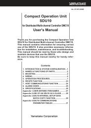
■ Features<br />
The DigitroniK <strong>SDC15</strong> is a 48 x 48mm compact digital<br />
controller featuring group multi-range inputs and PID<br />
control system using new algorithms "Rationaloop PID<br />
(Ra-Pid)" and "Just-FiTTER".<br />
Up to two control outputs (this number of points may vary<br />
depending on the model) can be used, which are selectable<br />
from the relay contact, voltage pulse, and current.<br />
Two kinds of mounting methods are provided, panel<br />
mounting type and socket mounting type.<br />
Additionally, this controller is compliant to the CE marking.<br />
• Compact body with a depth of 60 mm.<br />
The mask of the front panel is also only 2 mm thick.<br />
• The accuracy is ±0.5%FS.<br />
• The input type can be changed among the thermocouple<br />
input group, RTD group, and linear group.<br />
• The control method can be selected from any of the ON/<br />
OFF control, PID control using "Rationaloop PID (Ra-<br />
Pid) + Just-FiTTER", and self-tuning.<br />
• The heat and cool control can be achieved using two control<br />
outputs and event outputs.<br />
• 18 kinds of operations, such as set (SP) value selection,<br />
RUN/READY selection, and latch cancellation, etc. can<br />
be set using two external switch inputs.<br />
• The process variable (PV) value can be corrected.<br />
• The controller uses 3-wire RS-485 communications.<br />
• Up to eight points can be registered for the parameter<br />
keys, ensuring easy operation.<br />
• Use of "mode" key ensures easy operation, RUN/<br />
READY, AUTO/MANUAL, and SP selections, and EVrelay<br />
latch cancellation.<br />
• Up to three event outputs are provided.<br />
In addition to temperature events, such as PV, DEV, and<br />
SP, status events, such as CT heater burnout, over-current,<br />
and loop diagnosis can also be set.<br />
• The controller is compliant to the CE marking<br />
(safety standards EN61010-1 and EN61326).<br />
• Use of personal computer loader (optional unit) makes it<br />
possible to easily perform various settings, such as setup<br />
and parameter setting.<br />
• Use of personal computer loader makes it possible to easily<br />
achieve the data logging from single unit to up to eight<br />
units.<br />
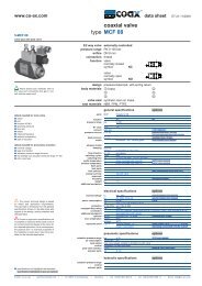
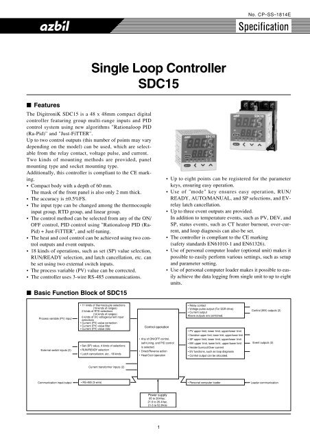
■ Basic Function Block of <strong>SDC15</strong><br />
Process variable (PV) input<br />
External switch inputs (2)<br />
• 11 kinds of thermocouple selections<br />
(19 kinds of ranges)<br />
2 kinds of RTD selections<br />
(14 kinds of ranges)<br />
6 kinds of DC voltage/current input<br />
selections<br />
• Current (PV) value correction<br />
• Current (PV) value filter<br />
• Current (PV) value ratio<br />
• Set (SP) value, 4 kinds of selections<br />
• RUN/READY selection<br />
• Latch cancellation, etc., 18 kinds<br />
Control operation<br />
• Any of ON/OFF control,<br />
self-tuning, and PID control<br />
is selected.<br />
• Direct/Reverse action<br />
• Heat/Cool operation<br />
• Relay contact<br />
• Voltage pulse output (For SSR drive)<br />
• Current output<br />
Above outputs are combined.<br />
• PV upper limit, lower limit, upper/lower limit<br />
• Deviation upper limit, lower limit, upper/lower limit<br />
• SP upper limit, lower limit, upper/lower limit<br />
• MV upper limit, lower limit, upper/lower limit<br />
• Heater burnout/Over-current<br />
• EV functions, such as loop diagnosis<br />
• Control output can be allocated.<br />
Control (MV) outputs (2)<br />
Event outputs (3)<br />
Current transformer inputs (2)<br />
Communication input/output<br />
• RS-485 (3-wire)<br />
• Personal computer loader<br />
Loader communication<br />
Power supply<br />
85 to 264Vac,<br />
21.6 to 26.4Vac,<br />
21.6 to 52.8Vdc<br />
1
■ Specifications<br />
PV input Input type Thermocouple, RTD, DC current, DC voltage (Selected by model. See Table 1.)<br />
Sampling time 0.5s<br />
Process variable (PV) -1999 to +9999 or -199.9 to +999.9<br />
correction<br />
Input bias current Thermocouple input: 0.2µA or less (under standard conditions)<br />
RTD input:<br />
Approx. 1mA (flowed from A-terminal)<br />
DC voltage input: 0 - 1V range: 1µA or less<br />
0 - 5V, 1 - 5V range: 3.5µA or less<br />
0 - 10V range: 7µA or less<br />
Effect of wiring Thermocouple input: 0.2µV/Ω or less<br />
resistance RTD input: ±0.05%FS/Ω or less<br />
DC voltage input: 0 - 1V range: 1µV/Ω or less<br />
0 - 5V, 1 - 5V range: 3.5µV/Ω or less<br />
0 - 10V range: 7µV/Ω or less<br />
Display at burnout Thermocouple input Upscale + alarm display (AL01)<br />
RTD input RTD burnout: Upscale + alarm display (AL01)<br />
A-wire burnout:<br />
Upscale + alarm display (AL01)<br />
B-wire burnout:<br />
Upscale + alarm display (AL01, AL03)<br />
C-wire burnout:<br />
Upscale + alarm display (AL01, AL03)<br />
2- or 3-wire burnout: Upscale + alarm display (AL01, AL03)<br />
A- and B-wire short-circuit: Downscale + alarm display (AL02)<br />
A- and C-wire short-circuit: Downscale + alarm display (AL02)<br />
DC voltage input:<br />
Downscale + alarm display (AL02)<br />
However, a voltage input ranging from 0 to 10V cannot<br />
be detected.<br />
DC current input:<br />
Downscale + alarm display (AL02)<br />
However, a current input ranging from 0 to 20mA<br />
cannot be detected.<br />
Indications PV, SP indication method 4-digit, 7-segment LED (PV: Upper green display, SP: Lower orange display)<br />
and setting<br />
Number of setting points Max. 4 points<br />
Setting method
Control output Just-FiTTER Overshoot suppression coefficient 0 to 100<br />
ON/OFF control Operation clearance (°C) 0 to 9999 or 0.0 to 999.9<br />
Control operation selection Direct action or reverse action<br />
RUN/READY selection Selected with the RDY key on the front panel or external contact input (In READY mode: Control output OFF)<br />
Heat/Cool control selection Control output and event output<br />
External Number of inputs 2<br />
contact<br />
Function<br />
Up to four kinds of setting value (SP) selections, RUN/READY selection, AUTO/MANUAL section, Auto tuning<br />
(digital input)<br />
stop/start, Self-turning disable/enable, Control action Direct/Reverse selection, SP ramp enable/disable, PV<br />
value hold, Max. PV value hold, Min. PV value hold, Timer start/stop, All DO latch cancellation<br />
Input rating<br />
Non-voltage contact or open collector<br />
Min. detection holding time 1s or longer<br />
Allowable ON contact Max. 250Ω<br />
resistance<br />
Allowable OFF Min.100kΩ<br />
contact resistance<br />
Allowable ON-state Max. 1.0V<br />
residual voltage<br />
Open terminal voltage 5.5Vdc±1V<br />
ON terminal voltage Approx. 7.5mA (at short-circuit), Approx. 5.0mA (at contact resistance of 250Ω)<br />
Event Number of outputs 0 to 3 (depending on the model)<br />
Number of internal Up to 5 settings<br />
event settings<br />
Event type PV high limit PV low limit<br />
● shows that the ON/<br />
OFF is changed at<br />
Direct action Reverse action Direct action Reverse action<br />
this value.<br />
shows that the ON/<br />
HYS ON<br />
ON HYS<br />
ON HYS<br />
HYS ON<br />
OFF is changed at<br />
Main setting<br />
Main setting<br />
Main setting<br />
Main setting<br />
a point that "1U" is<br />
PV<br />
PV<br />
PV<br />
PV<br />
added to this value.<br />
PV high/low limit<br />
Deviation high limit<br />
Direct action Reverse action Direct action Reverse action<br />
ON HYS HYS ON<br />
Main setting<br />
Sub-setting<br />
PV<br />
HYS<br />
Main setting<br />
ON<br />
HYS<br />
Sub-setting<br />
PV<br />
HYS ON<br />
SP + Main setting<br />
PV<br />
ON<br />
HYS<br />
SP + Main setting<br />
PV<br />
Deviation low limit<br />
Deviation high/low limit<br />
Direct action Reverse action Direct action Reverse action<br />
ON HYS<br />
SP + Main setting<br />
PV<br />
HYS ON<br />
SP + Main setting<br />
PV<br />
ON HYS HYS ON<br />
Main setting Sub-setting<br />
PV<br />
SP<br />
HYS<br />
ON<br />
HYS<br />
Main setting Sub-setting<br />
SP PV<br />
SP high limit<br />
SP low limit<br />
Direct action Reverse action Direct action Reverse action<br />
HYS<br />
ON<br />
ON<br />
HYS<br />
ON<br />
HYS<br />
<br />
<br />
Main setting<br />
SP<br />
Main setting<br />
SP<br />
Main setting<br />
SP<br />
<br />
<br />
SP high/low limit<br />
MV high limit<br />
Direct action Reverse action Direct action Reverse action<br />
ON HYS HYS ON<br />
Main setting<br />
Sub-setting<br />
SP<br />
HYS<br />
Main setting<br />
ON<br />
HYS<br />
Sub-setting<br />
SP<br />
HYS ON<br />
Main setting<br />
MV<br />
ON<br />
HYS<br />
Main setting<br />
MV<br />
MV low limit<br />
MV high/low limit<br />
Direct action Reverse action Direct action Reverse action<br />
ON<br />
HYS<br />
Main setting<br />
MV<br />
HYS<br />
Main setting<br />
ON<br />
MV<br />
ON HYS HYS ON<br />
Main setting<br />
Sub-setting<br />
MV<br />
HYS<br />
Main setting<br />
ON<br />
HYS<br />
Sub-setting<br />
MV<br />
Heater burnout/Over-current<br />
Heater short-circuit<br />
Direct action Reverse action Direct action Reverse action<br />
ON HYS HYS ON<br />
Main setting<br />
Sub-setting<br />
CT at output ON<br />
HYS<br />
Main setting<br />
ON HYS<br />
Sub-setting<br />
CT at output ON<br />
HYS<br />
ON<br />
Main setting<br />
CT at output OFF<br />
ON<br />
HYS<br />
Main setting<br />
CT at output OFF<br />
3
Event Event type <strong>Loop</strong> diagnosis 1<br />
● shows that the ON/<br />
OFF is changed at<br />
this value.<br />
shows that the ON/<br />
OFF is changed at<br />
a point that "1U" is<br />
added to this value.<br />
The event is turned ON when any change in PV corresponding to increase/decrease in MV (Manipulated<br />
variable) is not observed.<br />
This event is used to detect any fault of final control devices.<br />
● Setting items<br />
• Main setting: MV (Manipulated variable)<br />
• Sub-setting: PV<br />
• ON delay time: Diagnosis time<br />
● Operation specifications<br />
The event is turned ON when the value does not reach the PV set in the sub-setting within the diagnosis<br />
time (ON delay time) even though the MV exceeding the main setting is held.<br />
● CAUTION<br />
When setting the ON delay, it is necessary to put in "Multi-function setup".<br />
The default setting of the ON delay before shipment is 0.0s.<br />
Heat control<br />
Direct action<br />
Cool control<br />
Reverse action<br />
PV<br />
Sub-setting<br />
Area satisfying<br />
conditions 1<br />
HYS<br />
PV<br />
Sub-setting<br />
Area satisfying<br />
conditions 1<br />
HYS<br />
Time<br />
Time<br />
MV<br />
Area satisfying<br />
conditions 2<br />
MV<br />
Area satsifying<br />
conditions 2<br />
Main setting<br />
Main setting<br />
Time<br />
Conditions 3<br />
ON delay<br />
set time<br />
ON<br />
EV<br />
Time<br />
On delay is started when conditions 1 and 2 are saisfied.<br />
Time<br />
Conditions 3<br />
ON delay<br />
set time<br />
ON<br />
EV<br />
Time<br />
ON delay is started when conditions 1 and 2 are satisfied.<br />
<strong>Loop</strong> diagnosis 2<br />
The event is turned ON when any change in PV corresponding to increase/decrease in MV (Manipulated<br />
variable) is not observed.<br />
This event is used to detect any fault of final control devices.<br />
● Setting items<br />
• Main setting: MV (Manipulated variable)<br />
• Sub-setting: Change in PV from the point that the MV exceeds the main setting.<br />
• ON delay time: Diagnosis time<br />
● Operation specifications<br />
The event is turned ON when the MV exceeding the main setting is held (conditions 2) and the PV does<br />
not reach the value that the sub-setting is added to (subtracted from) the PV at the point where the MV<br />
exceeds the main setting within the diagnosis time (ON delay time) (conditions 1).<br />
● CAUTION<br />
When setting the ON delay, it is necessary to put in "Multi-function setup".<br />
The default setting of the ON delay before shipment is 0.0s.<br />
Direct action<br />
Reverse action<br />
Heat control<br />
Cool control<br />
PV<br />
PV to be used<br />
as reference<br />
Area satisfying<br />
conditions 1<br />
HYS<br />
Sub-setting<br />
(0 or more)<br />
PV<br />
PV to be used<br />
as reference<br />
Area satisfying<br />
conditions 1<br />
Sub-setting<br />
(0 or more)<br />
HYS<br />
Time<br />
Time<br />
MV<br />
Area satisfying<br />
conditions 2<br />
MV<br />
Area satisfying conditions 2<br />
Main setting<br />
Main setting<br />
Time<br />
Conditions 3<br />
ON delay<br />
set time<br />
ON<br />
EV<br />
Time<br />
ON delay is started when conditions 1 and 2 are satisfied.<br />
Time<br />
Conditions 3<br />
ON delay<br />
set time<br />
ON<br />
EV<br />
Time<br />
ON delay is started when conditions 1 and 2 are satisfied.<br />
4
Event Event type <strong>Loop</strong> diagnosis 1<br />
● shows that the ON/<br />
OFF is changed at<br />
.<br />
this value.<br />
This event is used to detect any fault of final control devices.<br />
shows that the ON/<br />
OFF is changed at<br />
a point that "1U" is<br />
added to this value.<br />
The event is turned ON when any change in PV corresponding to increase/decrease in MV (Manipulated<br />
variable) is not observed.<br />
● Setting items<br />
• Main setting: Change in PV from the point that the MV reaches the upper limit (100%) or lower limit (0%).<br />
• Sub-setting: Range of absolute value of deviation (PV – SP) allowing the event to turn OFF.<br />
• ON delay time: Diagnosis time<br />
• OFF delay time: A period of time from power ON allowing the event to turn OFF.<br />
● Operation specifications<br />
• The direct action is used for the heat control. The event is turned ON when the increase in PV becomes<br />
smaller than the main setting after the diagnosis time (ON delay time) has elapsed from the time that the MV<br />
had reached the upper limit, or when the decrease in PV becomes smaller than the main setting from the<br />
time that the diagnosis time (ON delay time) has elapsed from the time that the MV had reached the lower limit.<br />
• The reverse action is used for the cool control. The event is turned ON when the decrease in PV becomes<br />
smaller than the main setting after the diagnosis time (ON delay time) has elapsed from the time that the<br />
MV had reached the upper limit, or when the increase in PV becomes smaller than the main setting after<br />
the diagnosis time (ON delay time) has elapsed from the time that the MV had reached the lower limit.<br />
• The event is turned OFF regardless of other conditions when the absolute value of the deviation (PV – SP)<br />
becomes less than the sub-setting.<br />
• The event is turned OFF regardless of other conditions when a period of time after starting of operation<br />
from the time that the power has been turned ON becomes less than the OFF delay time.<br />
However, the event is turned OFF when the absolute value of the deviation is the (sub-setting – hysteresis)<br />
value or less after the absolute value of the deviation has become the sub-setting or more.<br />
● CAUTION<br />
When setting the ON delay and OFF delay, it is necessary to put in "Multi-function setup".<br />
The default settings of the ON delay and OFF delay before shipment are 0.0s.<br />
Heat control<br />
Direct action<br />
Cool control<br />
Reverse action<br />
PV<br />
PV to be<br />
used as<br />
reference<br />
Area satisfying<br />
conditions 2<br />
HYS<br />
PV to be used<br />
as reference<br />
Area satisfying<br />
conditions 2<br />
Main setting (0 or more)<br />
Main<br />
setting<br />
(0 or more)<br />
HYS<br />
PV<br />
PV to be<br />
used as<br />
reference<br />
Area satisfying<br />
conditions 1<br />
Main setting (0 or more)<br />
HYS<br />
Main setting (0 or more)<br />
Area satisfying<br />
conditions 1<br />
HYS<br />
Main setting<br />
(0 or more)<br />
PV to be used as reference<br />
Time<br />
Time<br />
MV<br />
Upper<br />
limit<br />
Lower<br />
limit<br />
Area satisfying<br />
conditions 2<br />
Area satisfying<br />
conditions 2<br />
Time<br />
Conditions 3<br />
Conditions 3<br />
ON delay<br />
ON delay<br />
set time<br />
ON<br />
set time<br />
ON<br />
EV<br />
Time<br />
ON delay is started when conditions 1 and 2 are satisfied.<br />
PV alarm (status)<br />
Direct action<br />
Reverse action<br />
ON if PV alarm (alarm code AL01 to 99) occurs, OFF if PV alarm (alarm code AL01 to 99) occurs,<br />
OFF in other cases.<br />
ON in other cases.<br />
READY (status)<br />
Direct action<br />
Reverse action<br />
ON in the READY mode.<br />
OFF in the READY mode.<br />
OFF in the RUN mode.<br />
ON in the RUN mode.<br />
MANUAL (status)<br />
Direct action<br />
Reverse action<br />
ON in the MANUAL mode.<br />
OFF in the MANUAL mode.<br />
OFF in the AUTO mode.<br />
ON in RUN mode.<br />
During AT (Auto tuning)<br />
Direct action<br />
Reverse action<br />
ON while AT is running.<br />
OFF while AT is running.<br />
OFF while AT is being stopped.<br />
ON while AT is being stopped.<br />
During SP ramp<br />
Direct action<br />
Reverse action<br />
ON during SP ramp.<br />
OFF during SP ramp.<br />
OFF when SP ramp is not performed or is completed. ON when SP ramp is not performed or is completed.<br />
Control operation (status)<br />
Direct action<br />
Reverse action<br />
ON during direct action (cooling).<br />
OFF during direct action (cooling).<br />
OFF during reverse action (heating).<br />
ON during reverse action (heating).<br />
5
Event Event type ST (Smart Tuning) setting standby (status)<br />
● shows that the ON/<br />
Direct action<br />
Reverse action<br />
OFF is changed at<br />
this value. ON in the ST setting standby.<br />
OFF in the ST setting standby.<br />
shows that the ON/<br />
OFF in the ST setting completion.<br />
ON in the ST setting completion.<br />
OFF is changed at<br />
Timer (status)<br />
a point that "1U" is<br />
The direct and reverse action settings are disabled for the timer event.<br />
added to this value.<br />
When using the timer event, it is necessary to set the operation type of the DI allocation to "Timer Start/Stop".<br />
Additionally, when setting the event channel designation of the DI allocation, multiple timer events are<br />
controlled from individual internal contacts (DI).<br />
● Setting items<br />
• ON delay time: A period of time necessary to change the event from OFF to ON after DI has been<br />
changed from OFF to ON.<br />
• OFF delay time: A period of time necessary to change the event from ON to OFF after DI has been<br />
changed from ON to OFF.<br />
● Operation specifications<br />
• The event is turned ON when DI ON continues for ON delay time or longer.<br />
• The event is turned OFF when DI OFF continues for OFF delay time or longer.<br />
• In other cases, the current status is continued.<br />
DI<br />
ON<br />
ON delay<br />
OFF delay<br />
Internal event<br />
● CAUTION<br />
When setting the ON delay and OFF delay, it is necessary to put in "Multi-function setup".<br />
The default settings of the ON delay and OFF delay before shipment are 0.0s.<br />
The default setting of the event channel designation of the DI allocation before shipment is "0". In this<br />
case, the timer event start/stop can be set for all internal events from one internal contact (DI).<br />
Additionally, as one or more event channel designation is set, the timer event start/stop can be set for one<br />
internal event specified by one internal contact (DI).<br />
However, when setting the event channel of the DI allocation, it is necessary to put in "Multi-function setup".<br />
Direct/Reverse action, standby, and READY operations can be set when setting up each event (E1.C1 to<br />
E5.C2).<br />
Operating differential 0 to 9999 or 0.0 to 999.9<br />
Output operation ON/OFF operation<br />
Output type<br />
SPST relay contacts, Common for 3 contacts/independent contact for 2 contacts<br />
Output rating 250Vac/30Vdc, 2A (resistive load)<br />
Life<br />
100,000 cycles or more<br />
Min. opening and 5V, 10mA<br />
closing specifications<br />
Communication Communication system Communication protocol RS-485<br />
Network<br />
Multidrop, This device is provided with the slave station function.<br />
1 to 31 units max.<br />
Data flow<br />
Half-duplex<br />
Synchronization method Start/stop synchronization<br />
Interface Transmission system Balance (differential) type<br />
Data line<br />
Bit serial<br />
Communication lines 3 transmit/receive lines<br />
Transmission speed 4800, 9600, 19200, 38400 bps<br />
Communication distance 500m max.<br />
Protocol<br />
RS-485 (3-wire type)<br />
Message characters Character configuration 11 bits/character<br />
Data length<br />
7 or 8 bits<br />
Stop bit length<br />
1 or 2 bits<br />
Parity bit<br />
Even parity, odd parity, or non-parity<br />
Loader Communication line 3-wire<br />
communication<br />
Transmission speed Fixed at 19200 bps<br />
Recommended cable Dedicated cable, 2 m long<br />
Current Number of inputs 2<br />
transformer<br />
Detection function Control output is ON.: Detection of heater line break or overcurrent<br />
input<br />
Control output is OFF.: Detection of final control devices short-circuit<br />
Input object<br />
Number of current transformer windings: 800 turns<br />
QN206A (5.8mm-hole diameter) Optional<br />
QN212A (12mm-hole diameter) Optional<br />
Measurement current 0.4 to 50A<br />
range<br />
Indication range 0.0 to 70.0A<br />
Indication accuracy ±5%FS±1 digit<br />
ON<br />
Time<br />
6
Current Indication resolution 0.1A<br />
transformer<br />
Output Selected from control output 1 and control output 2, or event output 1, event output 2, and event output 3.<br />
input<br />
Min. detection time Burnout detection: Min. control output ON time 300ms or more<br />
Final control device short-circuit detection: Min. control output OFF time 300ms or more<br />
General Memory backup Semiconductor non-volatile memory<br />
specifications Power supply voltage AC power supply model: 85 to 264Vac, 50/60Hz±2Hz.<br />
DC power supply model: 21.6 to 26.4Vac 50/60Hz±2Hz, 21.6 to 52.8Vdc<br />
Power consumption AC power supply model: 12VA or less.<br />
DC power supply model: 72VA or less (24Vac), 5W or less (24 tp 48Vdc)<br />
Insulation resistance Between power supply terminal and secondary terminal, 500Vdc, 10MΩ or more<br />
Dielectric strength AC power supply model: Between power supply terminal and secondary terminal, 1500Vac for 1 min.<br />
DC power supply model: Between power supply terminal and secondary terminal, 500Vac for 1 min.<br />
Power ON inrush current AC power supply model: 20A or less. DC power supply model: 20A or less.<br />
Operating conditions Ambient temperature 0 to 50°C (0 to 40°C for side-by-side mounting)<br />
Ambient humidity 10 to 90%RH (No condensation allowed)<br />
Vibration resistance 0 to 2m/s 2 (10 to 60Hz for 2 hrs. in each of X, Y, and Z directions)<br />
Shock resistance 0 to 10m/s 2<br />
Mounting angle Reference plane ±10°<br />
Transportation Ambient temperature -20 to +70°C<br />
conditions<br />
Ambient humidity 10 to 95%RH (No condensation allowed)<br />
Package drop test Drop height, 60cm, (1 corner, 3 sides, 6 planes, free fall)<br />
Mask and case Mask: Polyester film, Case: Modified PPE<br />
material<br />
Mask and case color Mask: Dark gray (DIC546), Case: Light gray (DIC650)<br />
Structure<br />
IP66<br />
Conformed standards EN61010-1, EN61326<br />
Installation category Category II (IEC644-1, EN61010-1)<br />
Mounting<br />
S type: Socket mounting (mounting with dedicated socket)<br />
T type: Panel mounting (with dedicated mounting bracket)<br />
Weight<br />
S type: Approx. 200g (including socket)<br />
T type: Approx. 150g (including dedicated mounting bracket)<br />
Standard Part name Model Q'ty Auxiliary parts Part name Model<br />
accessories<br />
Mounting bracket *1 81446403-001 1<br />
(optional parts) Mounting bracket *2 81446403-001<br />
User's manual CP-UM-5287E 1 Gasket *3 81446918-001<br />
(Installation) Current transformer QN206A (6mm-hole diameter)<br />
Gasket *1 81446918-001 1 QN212A (12mm-hole diameter)<br />
Table 1 Input Types and Ranges<br />
*1 Supplied only with C15T.<br />
*2 Connected to C15T.<br />
*3 Standard accessory<br />
Socket 81446391-001<br />
Hard cover 81446442-001<br />
Soft cover 81446443-001<br />
Terminal cover 81446898-001<br />
Input type C01 No. Sensor type Range (°C) Range (°F)<br />
Thermo- 1 K -200 to +1200 -300 to +2200<br />
couple 2 K 0 to 1200 0 to 2200<br />
3 K 0 to 800 0 to 1500<br />
4 K 0 to 600 0 to 1100<br />
5 K 0 to 400 0 to 700<br />
6 K -200 to +400 -300 to +700<br />
9 J 0 to 800 0 to 1500<br />
10 J 0 to 600 0 to 1100<br />
11 J -200 to +400 -300 to +700<br />
13 E 0 to 600 0 to 1100<br />
14 T -200 to +400 -300 to +700<br />
15 R 0 to 1600 0 to 3000<br />
16 S 0 to 1600 0 to 3000<br />
17 B 0 to 1800 0 to 3300<br />
18 N 0 to 1300 0 to 2300<br />
20 Wre5-26 0 to 1400 0 to 2400<br />
21 Wre5-26 0 to 2300 0 to 4200<br />
24 DIN U -200 to +400 -300 ot +700<br />
25 DIN L -100 to +800 -150 to +1500<br />
Handling Precautions<br />
• The accuracy of the B-thermocouple is ±5%FS at a temperature<br />
of 260°C or less and ±1%FS at a temperature of<br />
260 to 800°C.<br />
• The range having the decimal point is displayed to the 1st<br />
digit after the decimal point.<br />
• The setup is made using C01 No. according to the sensor<br />
type and range to be used.<br />
Input type C01 No. Sensor type Range (°C) Range (°F)<br />
RTD 41 Pt100 -200 to +500 -300 to +900<br />
42 JPt100 -200 to +500 -300 to +900<br />
43 Pt100 -200 to +200 -300 to +400<br />
44 JPt100 -200 to +200 -300 to +400<br />
45 Pt100 -100 to +300 -150 to +500<br />
46 JPt100 -100 to +300 -150 to +500<br />
51 Pt100 -50.0 to +200.0 -50 to +400<br />
52 JPt100 -50.0 to +200.0 -50 to +400<br />
53 Pt100 -50.0 to +100.0 -50 to +200<br />
54 JPt100 -50.0 to +100.0 -50 to +200<br />
63 Pt100 0.0 to 200.0 0 to 400<br />
64 JPt100 0.0 to 200.0 0 to 400<br />
67 Pt100 0 to 500 0 to 900<br />
68 JPt100 0 to 500 0 to 900<br />
Input type C01 No. Sensor type Range<br />
Linear input 84 0 to 1V<br />
86 1 to 5V<br />
The scaling is made in a range<br />
87 0 to 5V of -1999 to +9999.<br />
88 0 to 10V The decimal point position can<br />
89 0 to 20mA be changed variably.<br />
90 4 to 20mA<br />
7
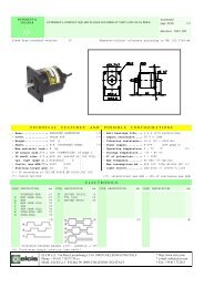
■ Model Selection Guide<br />
I II III IV V VI VII Example: C15TR0TA0000<br />
I II III IV V VI VII<br />
Basic Mounting Control PV Power Option Additional<br />
model output input supply processing<br />
No.<br />
C15<br />
(Note 1)<br />
T<br />
S<br />
(Note 2)<br />
(Note 3)<br />
(Note 3)<br />
(Note 3)<br />
Note 1. Socket sold separately<br />
Note 2. Only 1a contact is applicable for C15S<br />
Note 3. Can not be selected for the C15S<br />
Note 4. Current transformer sold separately<br />
Note 5. Can not be selected for DC Model<br />
<strong>Single</strong> <strong>Loop</strong> <strong>Controller</strong><br />
Panel mounting type<br />
Socket mounting type<br />
Specifications<br />
Control output 1 Control output 2<br />
R0 Relay output None<br />
V0 Voltage pulse output (For SSR drive) None<br />
VC Voltage pulse output (For SSR drive) Current output<br />
VV Voltage pulse output (For SSR drive) Voltage pulse output (For SSR drive)<br />
C0 Current output None<br />
CC Current output Current output<br />
T Thermocouple input (K, J, E, T, R, S, B, N, Wre5-26, DIN U, DIN L)<br />
R<br />
L<br />
A<br />
D<br />
(Note 3, 4)<br />
(Note 3, 4)<br />
(Note 5)<br />
(Note 3, 4, 5)<br />
(Note 3, 4, 5)<br />
00 None<br />
RTD input (Pt100/JPt100)<br />
DC voltage/current input<br />
(0 to 1Vdc, 1 to 5Vdc, 0 to 5Vdc, 0 to 10Vdc, 0 to 20mAdc, 4 to 20mAdc)<br />
AC Model (100 to 240Vac)<br />
DC Model (24Vac/24 to 48Vdc)<br />
01 Event relay outputs: 3<br />
Event relay outputs: 3<br />
02 Current transformer inputs: 2<br />
Digital inputs: 2<br />
Event relay outputs: 3<br />
03 Current transformer inpust: 2<br />
RS-485 communications<br />
04 Event relay outputs: 2 (independent contact)<br />
Event relay outputs: 2 (independent contact)<br />
05 Current transformer inputs: 2<br />
Digital inputs: 2<br />
Event relay outputs: 2 (independent contact)<br />
06 Current transformer inputs: 2<br />
RS-485 communications<br />
00 No additional processing<br />
D0<br />
Y0<br />
With inspection certificate<br />
Traceability certificate available<br />
8
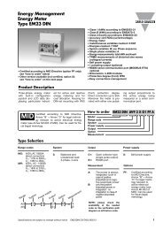
■ Dimensions<br />
● C15T (Panel mounting type)<br />
(Unit: mm)<br />
2<br />
60<br />
48<br />
Mounting bracket (Accessory)<br />
Terminal screw M3<br />
pv<br />
<strong>SDC15</strong><br />
48<br />
sp<br />
44.8<br />
59<br />
mode<br />
rdy man ev1 ev2 ev3 ot1 ot2<br />
para<br />
Handling Precautions<br />
Tighten the screws of the attached mounting bracket. When the mounting bracket is secured firmly so that no play<br />
exists, tighten the screws further by half-turn to fix the bracket to the panel. If the screws are tightened excessively,<br />
this may cause the case to deform.<br />
● C15S (Socket mounting type)<br />
● Socket 81446391-001 (Optional unit)<br />
74.2<br />
48<br />
61.2<br />
31<br />
26.5<br />
Terminal screw M3.5<br />
51<br />
8<br />
7<br />
6<br />
5<br />
pv<br />
<strong>SDC15</strong><br />
4<br />
2- M4 mounting hole<br />
48<br />
sp<br />
71<br />
mode<br />
rdy man ev1 ev2 ev3 ot1 ot2<br />
40<br />
para<br />
9<br />
3<br />
10 11<br />
1 2<br />
Stopper<br />
Socket<br />
3.4<br />
<br />
<br />
● Panel cutout diagram<br />
Individual mounting<br />
Side-by-side mounting<br />
30 min.<br />
+0.5<br />
45 0<br />
+0.5<br />
(48xN -3) 0<br />
45<br />
50 min.<br />
45<br />
+0.5<br />
0<br />
+0.5<br />
0<br />
("N" shows the number of mounted units.)<br />
Handling Precautions<br />
• When mounting three or more units tightly in the horizontal direction, pay<br />
special attention so that the ambient temperature does not exceed 40°C.<br />
• When the water-proof structure is required, always mount the unit individually<br />
after the gasket supplied with this controller has been mounted<br />
on the main body.<br />
• Keep a space of 50 mm or more in the vertical direction.<br />
9
■ Part Names and Functions<br />
(1)<br />
(4)<br />
pv<br />
sp<br />
mode<br />
rdy man ev1 ev2 ev3 ot1 ot2<br />
para<br />
(5) (6)<br />
(2)<br />
(3)<br />
(7)<br />
(1) Display No. 1: Shows the PV value (current temperature,<br />
etc.) or setting items.<br />
(2) Display No. 2: Shows the SP value (set temperature, etc.)<br />
or the set value of each setting item.<br />
(3) Mode indicators<br />
rdy : Lights in READY mode (control stop).<br />
man: Lights in MANUAL mode (manual operation<br />
mode).<br />
ev1 to ev3: Lights when event relay output is ON.<br />
ot1 to ot2: Lights when control output is ON.<br />
(4) [mode] key: When this key is kept pressed for 1s or<br />
longer, the operation which has been set previously<br />
can be performed.<br />
The default setting before shipment is the<br />
RUN/READY selection.<br />
(5) [para] key: Changes the display.<br />
(6)
● Precautions on the use of self-tuning function<br />
The final control devices must be powered up simultaneously<br />
with or prior to the instrument when the selftuning<br />
function is to be used.<br />
● Precautions on wiring<br />
1. Isolation within instrument<br />
Solid line portions " " are isolated.<br />
Dotted line portions " " are not isolated.<br />
Power supply Control output 1<br />
PV input Control output 2<br />
CT input 1<br />
Event output 1<br />
CT input 2 Internal (Indepndent<br />
Event output 1<br />
contact)<br />
Loader communication circuit Event output 2<br />
Event output 1<br />
Digital input 1 RS-485 Event output 3<br />
(Indepndent<br />
Digital input 2 communications<br />
contact)<br />
Available inputs and outputs may vary depending on the model.<br />
2. Preventive measures against noise of instrument<br />
power supply<br />
(1) Reduction of noise<br />
Even though the noise is small, the noise filter is used<br />
to eliminate the effect of the noise as much as possible.<br />
Instrument power supply<br />
100 to 240Vac<br />
Noise filter<br />
C15T<br />
11<br />
C15S<br />
10<br />
3. Installation environment noise sources and<br />
preventive measures<br />
Generally, the following may be the noise sources in the<br />
installation environment:<br />
Relay and contact, electromagnetic coil, solenoid valve,<br />
power supply line (particularly, 100Vac or more), motor<br />
commutator, phase angle control SCR, radio communication<br />
device, welding machine, high-voltage ignitor, etc.<br />
Preventive measures against fast rise noise<br />
Use of CR filter is effective to prevent fast rise noise.<br />
Recommended filter:<br />
Yamatake's model No. 81446365-001<br />
(Equivalent to 953M500333311 made by Matsuo<br />
Electric.)<br />
4. Wiring precautions<br />
(1) After taking the noise preventive measures, do not bundle<br />
the primary and secondary power cables together or put<br />
both power cables in the same conduit or duct.<br />
(2) Keep the input/output and communication lines 50 cm<br />
or more away from the power lines and power supply<br />
lines having a voltage of 100Vac or more.<br />
Additionally, do not put these lines together in the same<br />
conduit or duct.<br />
5. Inspection after wiring<br />
After the wiring work has been completed, always inspect<br />
and check the wiring status. Great care should<br />
be taken since incorrect wiring may cause the instrument<br />
to malfunction or severe personal injury.<br />
12<br />
11<br />
(2) When noise is excessive<br />
If a large amount of noise exists, appropriate isolation<br />
transformer and line filter are used to eliminate the<br />
effect of the noise.<br />
Instrument<br />
power supply<br />
100 to 240Vac<br />
Insulation<br />
transformer<br />
(100/100V)<br />
(200/200V)<br />
Line filter<br />
Yamatake's model No.<br />
E81446364-001<br />
(Equivalent to ZAC2205-00U<br />
made by TDK)<br />
1<br />
E<br />
2<br />
3<br />
GND<br />
4<br />
C15T<br />
11<br />
12<br />
C15S<br />
10<br />
11<br />
Other circuit<br />
Grounding<br />
11
RESTRICTIONS ON USE<br />
This product has been designed, developed and manufactured for general-purpose application in machinery and equipment.<br />
Accordingly, when used in the applications outlined below, special care should be taken to implement a fail-safe and/or redundant<br />
design concept as well as a periodic maintenance program.<br />
• Safety devices for plant worker protection • Start/stop control devices for transportation and material handling machines<br />
• Aeronautical/aerospace machines • Control devices for nuclear reactors<br />
Never use this product in applications where human safety may be put at risk.<br />
Specifications are subject to change without notice.<br />
Advanced Automation Company<br />
1-12-2 Kawana, Fujisawa<br />
Kanagawa 251-8522 Japan<br />
URL: http://www.azbil.com<br />
(08)<br />
12<br />
(H)<br />
1st Edition: Issued in May, 2003<br />
2nd Edition: Issued in Jun., 2008<br />
No part of this publication may be reproduced or duplicated<br />
without the prior written permission of Yamatake Corporation.