ST3000 Series 900 Smart Transmitter Remote-sealed type of ...
ST3000 Series 900 Smart Transmitter Remote-sealed type of ...
ST3000 Series 900 Smart Transmitter Remote-sealed type of ...

You also want an ePaper? Increase the reach of your titles
YUMPU automatically turns print PDFs into web optimized ePapers that Google loves.
No. SS2-STJ300-0100 (Rev.5)<br />
<strong>ST3000</strong> <strong>Series</strong> <strong>900</strong> <strong>Smart</strong> <strong>Transmitter</strong><br />
<strong>Remote</strong>-<strong>sealed</strong> <strong>type</strong> <strong>of</strong><br />
Differential Pressure <strong>Transmitter</strong>s<br />
Model STE929 / STE930<br />
OVERVIEW<br />
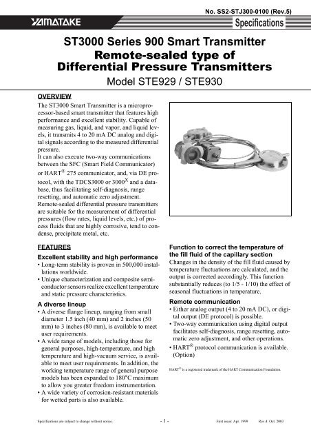
The <strong>ST3000</strong> <strong>Smart</strong> <strong>Transmitter</strong> is a microprocessor-based<br />
smart transmitter that features high<br />
performance and excellent stability. Capable <strong>of</strong><br />
measuring gas, liquid, and vapor, and liquid levels,<br />
it transmits 4 to 20 mA DC analog and digital<br />
signals according to the measured differential<br />
pressure.<br />
It can also execute two-way communications<br />
between the SFC (<strong>Smart</strong> Field Communicator)<br />
or HART ® 275 communicator, and, via DE protocol,<br />
with the TDCS3000 or 3000 X and a database,<br />
thus facilitating self-diagnosis, range<br />
resetting, and automatic zero adjustment.<br />
<strong>Remote</strong>-<strong>sealed</strong> differential pressure transmitters<br />
are suitable for the measurement <strong>of</strong> differential<br />
pressures (flow rates, liquid levels, etc.) <strong>of</strong> process<br />
fluids that are highly corrosive, tend to condense,<br />
precipitate metal, etc.<br />
FEATURES<br />
Excellent stability and high performance<br />
• Long-term stability is proven in 500,000 installations<br />
worldwide.<br />
• Unique characterization and composite semiconductor<br />
sensors realize excellent temperature<br />
and static pressure characteristics.<br />
A diverse lineup<br />
• A diverse flange lineup, ranging from small<br />
diameter 1.5 inch (40 mm) and 2 inches (50<br />
mm) to 3 inches (80 mm), is available to meet<br />
user requirements.<br />
• A wide range <strong>of</strong> models, including those for<br />
general purposes, high-temperature, and high<br />
temperature and high-vacuum service, is available<br />
to meet user requirements. In addition, the<br />
working temperature range <strong>of</strong> general purpose<br />
models has been expanded to 180°C maximum<br />
to allow you greater freedom instrumentation.<br />
• A wide variety <strong>of</strong> corrosion-resistant materials<br />
for wetted parts is also available.<br />
Function to correct the temperature <strong>of</strong><br />
the fill fluid <strong>of</strong> the capillary section<br />
Changes in the density <strong>of</strong> the fill fluid caused by<br />
temperature fluctuations are calculated, and the<br />
output is corrected accordingly. This function<br />
substantially reduces (to 1/5 - 1/10) the effect <strong>of</strong><br />
seasonal fluctuations in temperature.<br />
<strong>Remote</strong> communication<br />
• Either analog output (4 to 20 mA DC), or digital<br />
output (DE protocol) is possible.<br />
• Two-way communication using digital output<br />
facilitates self-diagnosis, range resetting, automatic<br />
zero adjustment, and other operations.<br />
•HART ® protocol communication is available.<br />
(Option)<br />
HART ® is a registered trademark <strong>of</strong> the HART Communication Foundation.<br />
Specifications are subject to change without notice. - 1 - First issue: Apr. 1999 Rev.4: Oct. 2003
No. SS2-STJ300-0100 (Rev.5)<br />
APPLICATION<br />
Petroleum / Petrochemical / Chemical<br />
• For the measurement <strong>of</strong> liquid levels including corrosive<br />
fluids at high temperatures, and high temperatures under<br />
vacuum<br />
• For the control <strong>of</strong> flow rates as used with tapless venturi<br />
tubes<br />
• For replacement <strong>of</strong> displacement <strong>type</strong> level gauges<br />
• For materialization <strong>of</strong> instrumentation without connecting<br />
tubes<br />
Electric power / City gas / Other utilities<br />
For measurement applications that require high degrees <strong>of</strong><br />
stability and accuracy.<br />
Pulp and paper<br />
• For lines that need transmitters resistant to chemical liquids,<br />
corrosive fluids and the like<br />
• For the measurement <strong>of</strong> liquid levels in small tanks<br />
• Iron and Steel / Nonferrous metal / Ceramics<br />
• For lines that require stable measurement under strictly<br />
controlled (temperature, humidity, etc.) conditions<br />
Iron and steel / Nonferrous metal / Ceramics<br />
For lines that require stable measurement under strictly<br />
controlled (temperature, humidity, vibration, etc.) conditions.<br />
Machinery / Shipbuilding<br />
For lines that require stable measurement under strictly<br />
controlled (temperature, humidity, etc.) conditions.<br />
Yamatake Corporation<br />
FUNCTIONAL SPECIFICATIONS<br />
Type <strong>of</strong> protection<br />
JIS C0920 watertight: NEMA3 and 4X<br />
JIS F8001 class 2 watertight: IEC IP67<br />
FM Explosionpro<strong>of</strong> approval<br />
Explosionpro<strong>of</strong> for Class I (Gas, steam), Division 1,<br />
Group A, B, C, D<br />
Dust-ignition for Class II (Inflammable dust), Division<br />
1, Group E, F, G<br />
Suitable for Class III (inflammable fiber), Division 1<br />
Nonincendive for Class I, Division 2, Group A, B, C,<br />
D<br />
FM Intrinsically safe approval<br />
Intrinsically safe for Class I, II, III, Division 1, Group<br />
A, B, C, D, E, F, G<br />
ATEX Flamepro<strong>of</strong> approval<br />
Certificate number: INERIS99ATEX0010 X<br />
II 2 GD EExd IIC T6 at -20 < Tamb < +60°C<br />
ATEX Intrinsic safety<br />
Certificate number: KEMA03ATEX1225 X<br />
II 1 G EEx ia IIC T4 at -20 < Tamb < +60°C<br />
Electrical data: Ui = 30V<br />
Ii = 100 mA<br />
Pi = 1W<br />
Ci = 3 nF<br />
Li = 0.5 mH<br />
SPECIAL CONDITIONS FOR SAFE USE (X)<br />
Because the enclosure <strong>of</strong> the <strong>Smart</strong> Pressure <strong>Transmitter</strong><br />
is made <strong>of</strong> aluminium, if it is mounted in an area<br />
where the use <strong>of</strong> category 1 G apparatus is required, it<br />
must be installed such, that, even in the event <strong>of</strong> rare<br />
incidents, ignition sources due to impact and friction<br />
sparks are excluded.<br />
NEPSI Flamepro<strong>of</strong> approval<br />
Ex d II T6 (with NEPSI Dust Ignition DIP DT T13)<br />
NEPSI Intrinsically safe approval<br />
Ex ia IIC T5 at -20 < Tamb < +60°C<br />
Ex ia IIC T6 at -20 < Tamb < +40°C<br />
CSA Explosion-pro<strong>of</strong> Approval<br />
CSA Explosion-pro<strong>of</strong> for Class I, (Division 1),<br />
Groups A, B, C and D<br />
CSA Flamepro<strong>of</strong> for Class I, Zone 1, Ex d IIC T6 at<br />
ambient temp. = -20°C to +60°C<br />
CSA Dust-ignitionpro<strong>of</strong> for Class II and III, (Division<br />
1), Groups E, F and G<br />
EMC Conformity<br />
89/336/EEC, 92/31/EEC, 93/68/EEC Electromagnetic<br />
Compatibility (EMC) Directive<br />
PED Conformity (97/23/EC)<br />
Comply with Module H (with “H1” option), or SEP<br />
(Sound Engineering Practice) for models <strong>of</strong> which<br />
maximum working pressure is 200 bar or lower.<br />
- 2 -
Yamatake Corporation<br />
Measuring span / Setting range / Working pressure<br />
range<br />
STE<br />
929<br />
STE<br />
930<br />
Figure 1<br />
Working pressure P (kPa {mmhg} abs.)<br />
Working pressure P (kPa {mmHg} abs.)<br />
Figure 2<br />
Measuring Span<br />
2.5 to100 kPa<br />
{250 to 10160<br />
mmH 2 O}<br />
35 to 700 kPa<br />
{0.35 to 7 kgf/<br />
cm 2 }<br />
133<br />
{1000}<br />
101<br />
{760}<br />
53<br />
{400}<br />
133.3<br />
101.3<br />
{760}<br />
80<br />
53<br />
27<br />
13<br />
8.0<br />
5.3<br />
2.0<br />
{15}<br />
1.3<br />
Operative limit<br />
Setting Range<br />
-100 to 100 kPa<br />
{-10160 to 10160<br />
mmH 2 O}<br />
-100 to 700 kPa<br />
{-1 to 7 kgf/cm 2 }<br />
Normal operating<br />
range<br />
Unusable range<br />
Temperature <strong>of</strong> wetted parts ( C)<br />
Working Pressure<br />
Range<br />
Up to flange rating<br />
(For negative pressures,<br />
see Figure 1,<br />
Figure 2 and Figure<br />
4.)<br />
-50 -40 40 50 60 70 80 90 100 110125 180185<br />
Working pressure and temperature <strong>of</strong> wetted<br />
parts section (for general purpose models)<br />
Normal operating<br />
conditions<br />
Operative limit conditions<br />
-40 -10 0 40 80 120 125<br />
Temperature <strong>of</strong> wetted parts ( C)<br />
Working pressure and temperature wetted<br />
parts section (for oxygen and chlorine service)<br />
Operative limit<br />
Operative limit<br />
conditions<br />
No. SS2-STJ300-0100 (Rev.5)<br />
a. For high temperature b. For high temperature and vacuum,<br />
c. For high temperature and high vacuum<br />
Figure 3 Working pressure temperature <strong>of</strong> wetted parts<br />
section (For high temperature / high temperature<br />
and vacuum / high temperature and high<br />
vacuum)<br />
Supply voltage and load resistance<br />
10.8 to 45 V DC. A load resistance <strong>of</strong> 250 Ω or more is<br />
necessary between loops. See Figure 4.<br />
Figure 4<br />
Load resistance (Ω)<br />
Working pressure (kPa abs.)<br />
1560<br />
605<br />
250<br />
101.3<br />
13<br />
2<br />
1.0<br />
0.6<br />
0.13<br />
0.013<br />
-40 0 40 100 200 250 300<br />
-5 10 50 90 280<br />
Temperature <strong>of</strong> wetted parts ( C)<br />
Load resistance (Ω)<br />
Supply voltage - 10.8<br />
=<br />
0.0218<br />
0 10.8 16.3 24 45<br />
Supply voltage (V DC)<br />
Supply voltage vs. load resistance characteristics<br />
Note) For communication with SFC, a load resistance <strong>of</strong> 250 Ω<br />
or more is necessary.<br />
For ATEX Intrinsic safety model, minimum voltage <strong>of</strong><br />
18.0V is required.<br />
Output<br />
Analog output (4 to 20 mA DC) with DE protocol<br />
Analog output (4 to 20 mA DC) with HART protocol<br />
Digital output (DE protocol)<br />
c<br />
a<br />
b<br />
Operating Range<br />
- 3 -
No. SS2-STJ300-0100 (Rev.5)<br />
Ambient temperature limits / Temperature<br />
ranges <strong>of</strong> wetted parts<br />
Wetted parts section<br />
Ambient temperature *2<br />
Flange size:<br />
Flush diaphragm <strong>type</strong> 3<br />
inches (80 mm)<br />
Extended diaphragm<br />
<strong>type</strong> 4 inches (100 mm)<br />
Ambient temperature<br />
Note 2<br />
Flange size:<br />
Flush diaphragm <strong>type</strong><br />
2 inches (50 mm) / 1.5<br />
inch (40 mm)<br />
Extended diaphragm<br />
<strong>type</strong> 3 inches (80 mm) /<br />
2 inches (50 mm)<br />
Specific gravity <strong>of</strong> fill fluid *3 0.935 1.07 1.07 1.09 1.87<br />
Note) *1: See the working pressures and temperatures <strong>of</strong> the wetted<br />
parts section in Figure 1, Figure 2 and Figure 4.<br />
*2: Ambient temperatures <strong>of</strong> the transmitter itself<br />
*3: Approximate values at the temperature <strong>of</strong> 25°C<br />
*4: Note that if the operating temperature falls below the lower<br />
limit <strong>of</strong> the normal operating range, the response <strong>of</strong> the<br />
transmitter becomes slower.<br />
*5: When the wetted parts material is tantalum, the upper limit<br />
is 180°C.<br />
*6: When the wetted parts material is tantalum, the upper limit<br />
is 200°C.<br />
For Explosion pro<strong>of</strong> models with digital indicators, which<br />
have to be used within the following ranges<br />
Normal operating condition<br />
-20 to 70°C<br />
Operative limit<br />
-30 to 80°C<br />
Normal<br />
operating<br />
range<br />
Operative<br />
limit<br />
range<br />
Normal<br />
operating<br />
range<br />
Operative<br />
limit<br />
range<br />
Normal<br />
operating<br />
range<br />
Operative<br />
limit<br />
range<br />
General<br />
purpose model<br />
Temperature range (°C) *1, *4<br />
-40 to<br />
180<br />
-50 to<br />
185<br />
-30 to<br />
75<br />
-50 to<br />
80<br />
-15 to<br />
65<br />
-30 to<br />
80<br />
High-temperature model<br />
-5 to<br />
280 *5<br />
-10 to<br />
310 *6<br />
-5 to<br />
55<br />
-10 to<br />
60<br />
-5 to<br />
45<br />
-10 to<br />
55<br />
High-temperature<br />
vacuum models<br />
-5 to<br />
280 *5<br />
-10 to<br />
310 *6<br />
-5 to<br />
55<br />
-10 to<br />
60<br />
-5 to<br />
55<br />
-10 to<br />
60<br />
High-temperature<br />
high-vacuum models<br />
10 to<br />
300 *5<br />
-10 to<br />
310 *6<br />
10 to<br />
55<br />
-10 to<br />
60<br />
10 to<br />
55<br />
-10 to<br />
60<br />
Oxygen and<br />
chlorine models<br />
-10 to<br />
120<br />
-40 to<br />
125<br />
-10 to<br />
75<br />
-40 to<br />
80<br />
-10 to<br />
75<br />
-40 to<br />
80<br />
Ambient temperature ( C)<br />
Yamatake Corporation<br />
Figure 5 Ambient temperature and temperature<br />
<strong>of</strong> wetted parts section (for general<br />
purpose models)<br />
[Flange diameter: Flush diaphragm 2 inches (50 mm) / 1.5 inch (40 mm)<br />
Extended diaphragm 3 inches (80 mm) / 2 inches (50 mm)]<br />
Note)<br />
Ambient temperature ( C)<br />
100<br />
80<br />
75<br />
72<br />
68<br />
50<br />
Normal operating<br />
range<br />
Operative limit range<br />
-50 -40 100 110 150 180185 200<br />
Temperature <strong>of</strong> wetted parts ( C)<br />
100<br />
80<br />
65<br />
61<br />
58<br />
50<br />
When the fill liquid is for general purposes, make sure<br />
before using your transmitter that the conditions in both<br />
Figure 1, Figure 5 and Figure 6 are met.<br />
Normal operating<br />
range<br />
-50 -40 100 110 150 180185 200<br />
Temperature <strong>of</strong> wetted parts ( C)<br />
Operative limit range<br />
Figure 6 Ambient temperature and temperature<br />
<strong>of</strong> wetted parts section (for general<br />
purpose models)<br />
[Flange diameter: Flush diaphragm 3 inches (80 mm)<br />
Extended diaphragm 4 inches (100 mm)]<br />
Ambient temperature ( C)<br />
60<br />
55<br />
33<br />
27<br />
Normal operating<br />
range<br />
Operative limit range<br />
-5<br />
-10<br />
-10 -5<br />
165180 280 310<br />
Temperature <strong>of</strong> wetted parts ( C)<br />
Figure 7 Ambient temperature and temperature<br />
<strong>of</strong> wetted parts section (for high<br />
temperature and vacuum 2, 3 m)<br />
[Flange diameter: Flush diaphragm 2 inches (50 mm) / 1.5 inch (40 mm)]<br />
- 4 -
Yamatake Corporation<br />
Ambient temperature ( C)<br />
Figure 8 Ambient temperature and temperature<br />
<strong>of</strong> wetted parts section (for high<br />
temperature and vacuum 4, 5 m)<br />
[Flange diameter: Flush diaphragm 2 inches (50 mm) / 1.5 inch (40 mm)]<br />
Ambient temperature ( C)<br />
Figure 9 Ambient temperature and temperature<br />
<strong>of</strong> wetted parts section (for high<br />
temperature and high vacuum 2, 3 m)<br />
[Flange diameter: Flush diaphragm 2 inches (50 mm) / 1.5 inch (40 mm)]<br />
Ambient temperature ( C)<br />
60<br />
55<br />
30<br />
27<br />
-5<br />
-10<br />
-10 -5<br />
100 125 280 310<br />
Temperature <strong>of</strong> wetted parts ( C)<br />
60<br />
55<br />
47<br />
43<br />
10<br />
Figure 10 Ambient temperature and temperature<br />
<strong>of</strong> wetted parts section (for high<br />
temperature and high vacuum 4, 5 m)<br />
[Flange diameter: Flush diaphragm 2 inches (50 mm) / 1.5 inch (40 mm)]<br />
Ambient humidity limits<br />
5 to 100% RH<br />
Stability against supply voltage change<br />
± 0.005% FS/V<br />
Dead time<br />
Approximately 0.4 sec.<br />
Normal operating<br />
range<br />
Damping time<br />
Selectable from 0 to 32 sec. in ten stages<br />
Operative limit range<br />
-10<br />
-10 10 230240 280 310<br />
Temperature <strong>of</strong> wetted parts ( C)<br />
60<br />
55<br />
41<br />
39<br />
10<br />
Normal operating<br />
range<br />
Normal operating<br />
range<br />
Operative limit range<br />
Operative limit range<br />
-10<br />
-10 10 160190 280 310<br />
Temperature <strong>of</strong> wetted parts ( C)<br />
No. SS2-STJ300-0100 (Rev.5)<br />
Correcting temperature <strong>of</strong> the capillary<br />
section fill fluid<br />
Changes in the density <strong>of</strong> the fill fluid (ρ) caused by temperature<br />
fluctuations are calculated, and the output is corrected<br />
accordingly. This function substantially reduces the<br />
effect <strong>of</strong> seasonal fluctuations in temperature.<br />
How to set this function<br />
Set the inter-flange height L (m) according to the SFC. If<br />
the height L (m) is already known, let us know, so, this<br />
function can be set before shipment.<br />
If the high pressure side (HP) <strong>of</strong> your transmitter is<br />
located under the tank, place a minus (-) sign before the<br />
height L setting.<br />
100% Level<br />
0% Level<br />
OPTIONAL SPECIFICATIONS<br />
Lightning protection<br />
Peak value <strong>of</strong> voltage surge: 200 kV<br />
Peak value <strong>of</strong> current surge: 2000 A<br />
Built-in indicating meter<br />
The digital LCD indicator (optional) indicates engineering<br />
units and can be set freely between -19999 and 19999 (4.5<br />
digits). For meter calibration, specify the following items<br />
when placing your order<br />
• Meter calibration range<br />
• Meter calibration unit<br />
• Proportional representation and instructions about<br />
square-root extraction<br />
Various kinds <strong>of</strong> data can be set using the SFC smart<br />
communicator (Ver. 7.1 or later) or HART ® 275 communicator.<br />
Bolts and nuts materials (for fastening<br />
meter body cover)<br />
Carbon steel (SNB7), SUS304, SUS630<br />
Corrosion-resistant finish<br />
Corrosion-resistant finish<br />
Corrosion-resistant paint (Baked acrylic paint), funguspro<strong>of</strong><br />
finish<br />
Corrosion-pro<strong>of</strong> finish<br />
Corrosion-pro<strong>of</strong> paint (Baked epoxy paint), funguspro<strong>of</strong><br />
finish<br />
Corrosion-resistant finish (silver paint)<br />
<strong>Transmitter</strong> case is coated with silver paint in addition to<br />
the above corrosion-resistant finish.<br />
FEP protective film<br />
Use FEP protective films when corrosive fluids are used or<br />
to inhibition migration from metal diaphragms.<br />
HP<br />
LP<br />
L (m)<br />
- 5 -
No. SS2-STJ300-0100 (Rev.5)<br />
Working temperature range<br />
0 to 110°C<br />
Working pressure range<br />
Atmospheric pressure to flange rating<br />
(up to JIS10K, ANSI / JPI 150)<br />
(Not usable under negative pressure)<br />
Oil free finish<br />
The transmitter is shipped with oil-free wetted parts.<br />
External zero/span adjustment function<br />
The transmitter can be easily zero/span adjusted in the field.<br />
Burnout feature<br />
Choice <strong>of</strong> three states at abnormal condition<br />
Burnout <strong>of</strong> output values: None, upper limit, lower limit<br />
Elbow<br />
This is an adaptor for changing the electrical conduit connection<br />
port from the horizontal to the vertical direction, if<br />
required by wiring conditions in the field. One or two<br />
elbows may be used as needed.<br />
Conformance to SI units<br />
We deliver transmitters set to any SI units as specified.<br />
PHYSICAL SPECIFICATIONS<br />
Materials<br />
Fill fluid<br />
Silicone oil for general purpose and high-temperature<br />
vacuum models<br />
Fluorine oil for oxygen and chlorine models<br />
For specific gravity, refer to “Ambient temperature limits<br />
/ Temperature ranges <strong>of</strong> wetted parts” on page 4.<br />
Center body<br />
SUS316<br />
<strong>Transmitter</strong> case<br />
Aluminum alloy<br />
Meter body cover<br />
SCS14A (SUS316L for diaphragm only)<br />
Hastelloy C, Tantalum, SUS316L<br />
For wetted parts<br />
SCS14A (SUS316L for diaphragm only)<br />
Hastelloy C, Tantalum, SUS316L<br />
Flange materials<br />
Carbon steel (SF440A), SUS304, SUS316, SUS316L<br />
Capillary section<br />
Capillary tube length<br />
2, 3, 4, 5, 6, 7, 8, 9 and 10 m<br />
2, 3, 4 and 5 m when flange diameter is flush diaphragm<br />
2 inches (50 mm) / 1.5 inch (40 mm) extended diaphragm<br />
3 inches (80 mm) / 2 inches (50 mm)<br />
Capillary tube material<br />
SUS316<br />
Armored tube material<br />
SUS304<br />
Yamatake Corporation<br />
Coating (optional)<br />
Olefin coating to improve corrosion resistance<br />
(Not applicable for high-temperature / Vacuum service<br />
<strong>type</strong> and High-temperature / High-vacuum service <strong>type</strong>.)<br />
Finish<br />
Baked acrylic paint<br />
Housing light beige (Munsell 4Y7.2/1.3)<br />
Cap dark beige (Munsell 10YR4.7/0.5)<br />
Weight<br />
Approx. 19.8 kg<br />
(Including JIS10K-80A flange and capillary 5 m long)<br />
INSTALLATION<br />
Electrical connection<br />
1/2NPT internal thread<br />
Grounding<br />
Resistance 100 Ω max.<br />
Mounting<br />
Direct mounting on the process side<br />
Using 2-inch pipe mounting brackets: Mount the transmitter<br />
on a horizontal or vertical 2-inch pipe.<br />
Bracket<br />
Carbon steel<br />
U-bolt and nuts<br />
SUS304<br />
Process connection<br />
Flange (both higher and lower pressure sides)<br />
Flush diaphragm<br />
JIS 10K, 20K and 30K: 80 / 50 / 40 mm (RF) equivalent<br />
ANSI 150, 300 and 600: 3 / 2 / 1.5 inches (RF) equivalents<br />
JPI 150, 300 and 600: 3 / 2 / 1.5 inches (RF) equivalents<br />
Extended diaphragm<br />
JIS 10K, 20K and 30K:100 / 80 / 50 mm (RF) equivalents<br />
ANSI 150 and 300: 4 / 3 / 2 inches (RF) equivalents<br />
JPI 150 and 300: 4 / 3 / 2 inches (RF) equivalents<br />
Mounting notes<br />
1) If the fluid to be measured contains hydrogen, please<br />
consult us.<br />
2) When mounting the transmitter, leave a space <strong>of</strong> at<br />
least 10 cm under the lower nozzle <strong>of</strong> the tank. If no<br />
space is available, please consult us.<br />
Upper liquid level<br />
Lower liquid level<br />
A>10cm<br />
- 6 -
Yamatake Corporation<br />
No. SS2-STJ300-0100 (Rev.5)<br />
PERFORMANCE SPECIFICATIONS<br />
Max working pressure<br />
Note 1. Max. working pressure depends on flange rating, flange materials and operating temperature. Please refer to<br />
the following data. Operating range <strong>of</strong> temperature depends on specification <strong>of</strong> transmitters.<br />
2. Max. working pressure depends on the smaller value <strong>of</strong> either 1.5 MPa or following data.<br />
3. Max. working pressure depends on the smaller value <strong>of</strong> either 10 MPa or following data.<br />
JIS<br />
JPI/ANSI<br />
Carbon steel<br />
Max. Working Pressure (MPa)<br />
12.0<br />
10.0<br />
8.0<br />
6.0<br />
4.0<br />
2.0<br />
0.0<br />
63K<br />
40K<br />
30K<br />
20K<br />
10K<br />
Max. Working Pressure (MPa)<br />
12.0<br />
10.0<br />
8.0<br />
6.0<br />
4.0<br />
2.0<br />
0.0<br />
600#<br />
300#<br />
150#<br />
SUS304<br />
Max. Working Pressure (MPa)<br />
12.0<br />
10.0<br />
8.0<br />
6.0<br />
4.0<br />
2.0<br />
0.0<br />
63K<br />
40K<br />
30K<br />
20K<br />
10K<br />
Max. Working Pressure (MPa)<br />
12.0<br />
10.0<br />
8.0<br />
6.0<br />
4.0<br />
2.0<br />
0.0<br />
600#<br />
300#<br />
150#<br />
SUS316<br />
Max. Working Pressure (MPa)<br />
12.0<br />
10.0<br />
8.0<br />
6.0<br />
4.0<br />
2.0<br />
0.0<br />
63K<br />
40K<br />
30K<br />
20K<br />
10K<br />
Max. Working Pressure (MPa)<br />
12.0<br />
10.0<br />
8.0<br />
6.0<br />
4.0<br />
2.0<br />
0.0<br />
600#<br />
300#<br />
150#<br />
SUS316L<br />
Max. Working Pressure (MPa)<br />
12.0<br />
10.0<br />
8.0<br />
6.0<br />
4.0<br />
2.0<br />
0.0<br />
63K<br />
40K<br />
30K<br />
20K<br />
10K<br />
Max. Working Pressure (MPa)<br />
12.0<br />
10.0<br />
8.0<br />
6.0<br />
4.0<br />
2.0<br />
0.0<br />
600#<br />
300#<br />
150#<br />
- 7 -
No. SS2-STJ300-0100 (Rev.5)<br />
Yamatake Corporation<br />
Accuracy<br />
χ<br />
Shown for each item are the percentage ratio for (kPa), which is the greatest value <strong>of</strong> either the upper range value<br />
(URV) *1 , the lower range value (LRV) *2 or the span.<br />
Model STE929 (for regular <strong>type</strong> / high-temperature service / oxygen service)<br />
Material <strong>of</strong> wetted parts: SUS316, SUS316L<br />
Flange size: Flush diaphragm 3 inches (80 mm) Extended diaphragm 4 inches (100 mm)<br />
Accuracy ± 0.2% (For χ > 12.5 kPa (1250 mmH 2 O))<br />
12.5<br />
± (0.05 + 0.15 × --------- )%<br />
χ<br />
(For χ < 12.5 kPa (1250 mmH 2 O))<br />
Temperature characteristics<br />
(Shift from the set<br />
χ<br />
Zero shift<br />
25<br />
± (0.14 + 0.27 × ----- )% χ: kPa<br />
range) Change <strong>of</strong> 30ºC<br />
(Range from -5 to 55ºC) Combined shift ± 0.71% (For χ > 25 kPa (2500 mmH 2 O))<br />
25<br />
± (0.38+ 0.33 × ----- )%<br />
χ<br />
(For χ < 25 kPa (2500 mmH 2 O))<br />
Static pressure effect Zero shift ± 0.75% (For χ > 25 kPa (2500 mmH 2 O))<br />
(Shift from the set<br />
25<br />
range) Change <strong>of</strong> 7 MPa<br />
± (0.75 × ----- )%<br />
χ<br />
(For χ < 25 kPa (2500 mmH 2 O))<br />
(70 kgf/cm 2 )<br />
Combined shift ± 1.00% (For χ > 25 kPa (2500 mmH 2 O))<br />
25<br />
± (1.00 × ----- )%<br />
χ<br />
(For χ < 25 kPa (2500 mmH 2 O))<br />
Model STE930 (for regular <strong>type</strong> / high-temperature service / oxygen service)<br />
Material <strong>of</strong> wetted parts: SUS316, SUS316L<br />
Flange size: Flush diaphragm 3 inches (80 mm) Extended diaphragm 4 inches (100mm)<br />
Accuracy (*3) ± 0.2% (For χ > 210 kPa (2.1 kgf/cm 2 ))<br />
210<br />
± (0.05 + 0.15 × -------- )%<br />
χ<br />
(For χ < 210 kPa (2.1 kgf/cm 2 ))<br />
Temperature characteristics<br />
(Shift from the set<br />
χ<br />
Zero shift<br />
210<br />
± (0.14 + 0.27 × -------- )% χ: kPa<br />
range) Change <strong>of</strong> 30ºC<br />
(*3) (Range from -5 to Combined shift ± 0.71% (For χ > 210 kPa (2.1 kgf/cm 2 ))<br />
55ºC)<br />
210<br />
± (0.38+ 0.33 × -------- )%<br />
χ<br />
(For χ < 210 kPa (2.1 kgf/cm 2 ))<br />
Static pressure effect Zero shift<br />
700<br />
± (0.75 × -------- )%<br />
(Shift from the set<br />
χ<br />
χ: kPa<br />
range) Change <strong>of</strong> 7 MPa<br />
(70 kgf/cm 2 )<br />
Combined shift<br />
700<br />
± (1.00 × -------- )%<br />
χ<br />
χ: kPa<br />
Note) *1 URV denotes the process value for 100% (20 mA DC) output<br />
*2 LRV denotes the process value for 0% (4 mA DC) output<br />
*3 Within a range <strong>of</strong> URV > 0 and LRV > 0<br />
- 8 -
Yamatake Corporation<br />
No. SS2-STJ300-0100 (Rev.5)<br />
Model STE929 (for regular <strong>type</strong> / high-temperature / oxygen / chlorine service)<br />
Material <strong>of</strong> wetted parts: Hastelloy C, Tantalum<br />
Flange size: Flush diaphragm 3 inches (80 mm)<br />
Accuracy ± 0.4% (For χ > 12.5 kPa (1250 mmH 2 O))<br />
Temperature characteristics<br />
(Shift from the set<br />
range) Change <strong>of</strong> 30ºC<br />
(Range from -5 to 55ºC)<br />
Static pressure effect<br />
(Shift from the set<br />
range) Change <strong>of</strong> 7 MPa<br />
(70 kgf/cm 2 )<br />
12.5<br />
± (0.4 × --------- )%<br />
χ<br />
(For χ < 12.5 kPa (1250 mmH 2 O))<br />
Zero shift ± 2.15% (For χ > 25 kPa (2500 mmH 2 O))<br />
25<br />
± (2.15 × ----- )%<br />
χ<br />
(For χ < 25 kPa (2500 mmH 2 O))<br />
Combined shift ± 3.0% (For χ > 25 kPa (2500 mmH 2 O))<br />
25<br />
± (3.0 × ----- )%<br />
χ<br />
(For χ < 25 kPa (2500 mmH 2 O))<br />
Zero shift ± 6.00% (For χ > 25 kPa (2500 mmH 2 O))<br />
25<br />
± (6.00 × ----- )%<br />
χ<br />
(For χ < 25 kPa (2500 mmH 2 O))<br />
Combined shift ± 7.00% (For χ > 25 kPa (2500 mmH 2 O))<br />
25<br />
± (7.00 × ----- )%<br />
χ<br />
(For χ < 25 kPa (2500 mmH 2 O))<br />
Model STE930 (for regular <strong>type</strong> / high-temperature / oxygen / chlorine service)<br />
Material <strong>of</strong> wetted parts: Hastelloy C, Tantalum<br />
Flange size: Flush diaphragm 3 inches (80 mm)<br />
Accuracy (*3) ± 0.2% (For χ > 210 kPa (2.1 kgf/cm 2 ))<br />
Temperature characteristics<br />
(Shift from the set<br />
range) Change <strong>of</strong> 30ºC<br />
(*3) (Range from -5 to<br />
55ºC)<br />
Static pressure effect<br />
(Shift from the set<br />
range) Change <strong>of</strong> 7 MPa<br />
(70 kgf/cm 2 )<br />
210<br />
± (0.05 + 0.15 × -------- )%<br />
χ<br />
(For χ < 210 kPa (2.1 kgf/cm 2 ))<br />
Zero shift<br />
210<br />
± (0.15 + 0.7 × -------- )%<br />
χ<br />
χ: kPa<br />
Combined shift ± 1.75% (For χ > 210 kPa (2.1 kgf/cm 2 ))<br />
210<br />
± (1.00 + 0.75 × -------- )%<br />
χ<br />
(For χ < 210 kPa (2.1 kgf/cm 2 ))<br />
Zero shift<br />
Combined shift<br />
700<br />
± (0.75 × -------- )%<br />
χ<br />
χ: kPa<br />
700<br />
± (1.00 × -------- )%<br />
χ<br />
χ: kPa<br />
Note) *3 Within a range <strong>of</strong> URV > 0 and LRV > 0<br />
- 9 -
No. SS2-STJ300-0100 (Rev.5)<br />
Yamatake Corporation<br />
Model STE929 (for regular <strong>type</strong> / high-temperature service / oxygen service)<br />
Material <strong>of</strong> wetted parts: SUS316, SUS316L<br />
Flange size: Flush diaphragm 2 inches (50 mm) Extended diaphragm 3 inches (80mm)<br />
Accuracy ± 0.2% (For χ > 12.5 kPa (1250 mmH 2 O))<br />
12.5<br />
± (0.05 + 0.15 × --------- )%<br />
χ<br />
(For χ < 12.5 kPa (1250 mmH 2 O))<br />
Temperature characteristics<br />
(Shift from the set<br />
χ<br />
Zero shift<br />
25<br />
± (0.14 + 0.27 × ----- )% χ: kPa<br />
range) Change <strong>of</strong> 30ºC<br />
(Range from -5 to 55ºC) Combined shift ± 0.88% (For χ > 25 kPa (2500 mmH 2 O))<br />
25<br />
± (0.55 + 0.33 × ----- )%<br />
χ<br />
(For χ < 25 kPa (2500 mmH 2 O))<br />
Static pressure effect Zero shift ± 1.47% (For χ > 25 kPa (2500 mmH 2 O))<br />
(Shift from the set<br />
25<br />
range) Change <strong>of</strong> 7 MPa<br />
± (1.47 × ----- )%<br />
χ<br />
(For χ < 25 kPa (2500 mmH 2 O))<br />
(70 kgf/cm 2 )<br />
Combined shift ± 1.97% (For χ > 25 kPa (2500 mmH 2 O))<br />
25<br />
± (1.97 × ----- )%<br />
χ<br />
(For χ < 25 kPa (2500 mmH 2 O))<br />
Model STE929 (for regular <strong>type</strong> / oxygen service)<br />
Material <strong>of</strong> wetted parts: SUS316, SUS316L<br />
Flange size: Flush diaphragm 1.5 inch (40 mm)<br />
Accuracy ± 0.3% (For χ > 12.5 kPa (1250 mmH 2 O))<br />
12.5<br />
± (0.3 × --------- )%<br />
χ<br />
(For χ < 12.5 kPa (1250 mmH 2 O))<br />
Temperature characteristics<br />
Zero shift ± 0.41% (For χ > 25 kPa (2500 mmH 2 O))<br />
(Shift from the set<br />
25<br />
range) Change <strong>of</strong> 30ºC<br />
± (0.41 × ----- )%<br />
χ<br />
(For χ < 25 kPa (2500 mmH 2 O))<br />
(Range from -5 to 55ºC) Combined shift ± 0.88% (For χ > 25 kPa (2500 mmH 2 O))<br />
25<br />
± (0.88 × ----- )%<br />
χ<br />
(For χ < 25 kPa (2500 mmH 2 O))<br />
Static pressure effect Zero shift ± 1.47% (For χ > 25 kPa (2500 mmH 2 O))<br />
(Shift from the set<br />
25<br />
range) Change <strong>of</strong> 7 MPa<br />
± (1.47 × ----- )%<br />
χ<br />
(For χ < 25 kPa (2500 mmH 2 O))<br />
(70 kgf/cm 2 )<br />
Combined shift ± 1.97% (For χ > 25 kPa (2500 mmH 2 O))<br />
25<br />
± (1.97 × ----- )%<br />
χ<br />
(For χ < 25 kPa (2500 mmH 2 O))<br />
Model STE929 (for high-temperature service)<br />
Material <strong>of</strong> wetted parts: SUS316, SUS316L<br />
Flange size: Flush diaphragm 1.5 inch (40 mm)<br />
Accuracy ± 0.3% (For χ > 12.5 kPa (1250 mmH 2 O))<br />
12.5<br />
± (0.3 × --------- )%<br />
χ<br />
(For χ < 12.5 kPa (1250 mmH 2 O))<br />
Temperature characteristics<br />
Zero shift ± 1.08% (For χ > 25 kPa (2500 mmH 2 O))<br />
(Shift from the set<br />
25<br />
range) Change <strong>of</strong> 30ºC<br />
± (1.08 × ----- )%<br />
χ<br />
(For χ < 25 kPa (2500 mmH 2 O))<br />
(Range from -5 to 55ºC) Combined shift ± 6.54% (For χ > 25 kPa (2500 mmH 2 O))<br />
25<br />
± (6.54 × ----- )%<br />
χ<br />
(For χ < 25 kPa (2500 mmH 2 O))<br />
Static pressure effect Zero shift ± 2.7% (For χ > 25 kPa (2500 mmH 2 O))<br />
(Shift from the set<br />
25<br />
range) Change <strong>of</strong> 7 MPa<br />
± (2.7 × ----- )%<br />
χ<br />
(For χ < 25 kPa (2500 mmH 2 O))<br />
(70 kgf/cm 2 )<br />
Combined shift ± 3.5% (For χ > 25 kPa (2500 mmH 2 O))<br />
25<br />
± (3.5 × ----- )%<br />
χ<br />
(For χ < 25 kPa (2500 mmH 2 O))<br />
Note) *3 Within a range <strong>of</strong> URV > 0 and LRV > 0<br />
- 10 -
Yamatake Corporation<br />
No. SS2-STJ300-0100 (Rev.5)<br />
Model STE929 (for regular <strong>type</strong> / high-temperature service / oxygen service)<br />
Material <strong>of</strong> wetted parts: SUS316, SUS316L<br />
Flange size: Extended diaphragm 2 inches (50 mm)<br />
Accuracy ± 0.3% (For χ > 12.5 kPa (1250 mmH 2 O))<br />
Temperature characteristics<br />
(Shift from the set<br />
range) Change <strong>of</strong> 30ºC<br />
(Range from -5 to 55ºC)<br />
Static pressure effect<br />
(Shift from the set<br />
range) Change <strong>of</strong> 7 MPa<br />
(70 kgf/cm 2 )<br />
12.5<br />
± (0.3 × --------- )%<br />
χ<br />
(For χ < 12.5 kPa (1250 mmH 2 O))<br />
Zero shift ± 1.08% (For χ > 25 kPa (2500 mmH 2 O))<br />
25<br />
± (1.08 × ----- )%<br />
χ<br />
(For χ < 25 kPa (2500 mmH 2 O))<br />
Combined shift ± 6.54% (For χ > 25 kPa (2500 mmH 2 O))<br />
25<br />
± (6.54 × ----- )%<br />
χ<br />
(For χ < 25 kPa (2500 mmH 2 O))<br />
Zero shift ± 2.7% (For χ > 25 kPa (2500 mmH 2 O))<br />
25<br />
± (2.7 × ----- )%<br />
χ<br />
(For χ < 25 kPa (2500 mmH 2 O))<br />
Combined shift ± 3.5% (For χ > 25 kPa (2500 mmH 2 O))<br />
25<br />
± (3.5 × ----- )%<br />
χ<br />
(For χ < 25 kPa (2500 mmH 2 O))<br />
Model STE929 (for regular <strong>type</strong> / high-temperature / oxygen / chlorine service)<br />
Material <strong>of</strong> wetted parts: Hastelloy C, Tantalum<br />
Flange size: Flush diaphragm 2 inches (50 mm), 1.5 inch (40 mm)<br />
Accuracy ± 0.4% (For χ > 12.5 kPa (1250 mmH 2 O))<br />
12.5<br />
± (0.4 × --------- )%<br />
χ<br />
(For χ < 12.5 kPa (1250 mmH 2 O))<br />
Temperature characteristics<br />
Zero shift ± 2.15% (For χ > 25 kPa (2500 mmH 2 O))<br />
(Shift from the set<br />
25<br />
range) Change <strong>of</strong> 30ºC<br />
± (2.15 × ----- )% (For χ < 25 kPa (2500 mmH 2 O))<br />
χ<br />
(Range from -5 to 55ºC)<br />
Combined shift ± 6.55% (For χ > 25 kPa (2500 mmH 2 O))<br />
Static pressure effect<br />
(Shift from the set<br />
range) Change <strong>of</strong> 7 MPa<br />
(70 kgf/cm 2 )<br />
25<br />
± (6.55 × ----- )%<br />
χ<br />
(For χ < 25 kPa (2500 mmH 2 O))<br />
Zero shift ± 6.00% (For χ > 25 kPa (2500 mmH 2 O))<br />
25<br />
± (6.00 × ----- )%<br />
χ<br />
(For χ < 25 kPa (2500 mmH 2 O))<br />
Combined shift ± 7.00% (For χ > 25 kPa (2500 mmH 2 O))<br />
Note) *3 Within a range <strong>of</strong> URV > 0 and LRV > 0<br />
25<br />
± (7.00 × ----- )% (For χ < 25 kPa (2500 mmH 2 O))<br />
χ<br />
- 11 -
No. SS2-STJ300-0100 (Rev.5)<br />
Yamatake Corporation<br />
Model STE930 (for regular <strong>type</strong> / high-temperature service / oxygen service)<br />
Material <strong>of</strong> wetted parts: SUS316, SUS316L<br />
Flange size: Flush diaphragm 2 inches (50 mm), 1.5 inch (40 mm) Extended diaphragm 3 inches (80 mm), 2 inches (50 mm)<br />
Accuracy (*3) ± 0.2% (For χ > 210 kPa (2.1 kgf/cm 2 ))<br />
Temperature characteristics<br />
(Shift from the set<br />
range) Change <strong>of</strong> 30ºC<br />
(*3) (Range from -5 to<br />
55ºC)<br />
Static pressure effect<br />
(Shift from the set<br />
range) Change <strong>of</strong> 7 MPa<br />
(70 kgf/cm 2 )<br />
210<br />
± (0.05 + 0.15 × -------- )%<br />
χ<br />
(For χ < 210 kPa (2.1 kgf/cm 2 ))<br />
Zero shift<br />
210<br />
± (0.14 + 0.27 × -------- )%<br />
χ<br />
χ: kPa<br />
Combined shift ± 1.53% (For χ > 210 kPa (2.1 kgf/cm 2 ))<br />
210<br />
± (1.2+ 0.33 × -------- )%<br />
χ<br />
(For χ < 210 kPa (2.1 kgf/cm 2 ))<br />
Zero shift<br />
Combined shift<br />
700<br />
± (0.03 + 0.47 × -------- )%<br />
χ<br />
χ: kPa<br />
700<br />
± (0.03 + 0.72 × -------- )%<br />
χ<br />
χ: kPa<br />
Model STE930 (for regular <strong>type</strong> / high-temperature / oxygen / chlorine service)<br />
Material <strong>of</strong> wetted parts: Hastelloy C, Tantalum<br />
Flange size: Flush diaphragm 2 inches (50 mm), 1.5 inch (40 mm)<br />
Accuracy (*3) ± 0.2% (For χ > 210 kPa (2.1 kgf/cm 2 ))<br />
Temperature characteristics<br />
(Shift from the set<br />
range) Change <strong>of</strong> 30ºC<br />
(*3) (Range from -5 to<br />
55ºC)<br />
Static pressure effect<br />
(Shift from the set<br />
range) Change <strong>of</strong> 7 MPa<br />
(70 kgf/cm 2 )<br />
210<br />
± (0.05 + 0.15 × -------- )%<br />
χ<br />
(For χ < 210 kPa (2.1 kgf/cm 2 ))<br />
Zero shift<br />
210<br />
± (0.15 + 0.7 × -------- )%<br />
χ<br />
χ: kPa<br />
Combined shift ± 3.0% (For χ > 210 kPa (2.1 kgf/cm 2 ))<br />
210<br />
± (2.2+ 0.8 × -------- )%<br />
χ<br />
(For χ < 210 kPa (2.1 kgf/cm 2 ))<br />
Zero shift<br />
Combined shift<br />
700<br />
± (0.03 + 0.47 × -------- )%<br />
χ<br />
χ: kPa<br />
700<br />
± (0.03 + 0.72 × -------- )%<br />
χ<br />
χ: kPa<br />
Note) *3 Within a range <strong>of</strong> URV > 0 and LRV > 0<br />
- 12 -
Yamatake Corporation<br />
No. SS2-STJ300-0100 (Rev.5)<br />
Model STE929 (for high temperature and vacuum / high temperature and high vacuum)<br />
Material <strong>of</strong> wetted parts: SUS316, SUS316L<br />
Flange size: Flush diaphragm 3 inches (80 mm) Extended diaphragm 4 inches (100mm)<br />
Accuracy ± 0.3% (For χ > 12.5 kPa (1250 mmH 2 O))<br />
12.5<br />
± (0.3 × --------- )%<br />
χ<br />
(For χ < 12.5 kPa (1250 mmH 2 O))<br />
Temperature characteristics<br />
Zero shift ± 0.81% (For χ > 25 kPa (2500 mmH 2 O))<br />
(Shift from the set<br />
25<br />
range) Change <strong>of</strong> 30ºC<br />
± (0.81 × ----- )%<br />
χ<br />
(For χ < 25 kPa (2500 mmH 2 O))<br />
(Range from -5 to 55ºC) Combined shift ± 1.36% (For χ > 25 kPa (2500 mmH 2 O))<br />
25<br />
± (1.36 × ----- )%<br />
χ<br />
(For χ < 25 kPa (2500 mmH 2 O))<br />
Static pressure effect Zero shift ± 6.0% (For χ > 25 kPa (2500 mmH 2 O))<br />
(Shift from the set<br />
25<br />
range) Change <strong>of</strong> 7 MPa<br />
± (6.0 × ----- )%<br />
χ<br />
(For χ < 25 kPa (2500 mmH 2 O))<br />
(70 kgf/cm 2 )<br />
Combined shift ± 7.0% (For χ > 25 kPa (2500 mmH 2 O))<br />
25<br />
± (7.0 × ----- )%<br />
χ<br />
(For χ < 25 kPa (2500 mmH 2 O))<br />
Model STE930 (for high temperature and vacuum / high temperature and high vacuum)<br />
Material <strong>of</strong> wetted parts: SUS316, SUS316L<br />
Flange size: Flush diaphragm 3 inches (80 mm) Extended diaphragm 4 inches (100mm)<br />
Accuracy (*3) ± 0.2% (For χ > 210 kPa (2.1 kgf/cm 2 ))<br />
210<br />
± (0.05 + 0.15 × -------- )%<br />
χ<br />
(For χ < 210 kPa (2.1 kgf/cm 2 ))<br />
Temperature characteristics<br />
(Shift from the set<br />
χ<br />
Zero shift<br />
210<br />
± (0.15 + 0.7 × -------- )% χ: kPa<br />
range) Change <strong>of</strong> 30ºC<br />
(*3) (Range from -5 to Combined shift ± 1.75% (For χ > 210 kPa (2.1 kgf/cm 2 ))<br />
55ºC)<br />
210<br />
± (1.00+ 0.75 × -------- )%<br />
χ<br />
(For χ < 210 kPa (2.1 kgf/cm 2 ))<br />
Static pressure effect Zero shift<br />
700<br />
± (0.75 × -------- )%<br />
(Shift from the set<br />
χ<br />
χ: kPa<br />
range) Change <strong>of</strong> 7 MPa<br />
(70 kgf/cm 2 )<br />
Combined shift<br />
700<br />
± (1.00 × -------- )%<br />
χ<br />
χ: kPa<br />
Model STE929 (for high temperature and vacuum / high temperature and high vacuum)<br />
Material <strong>of</strong> wetted parts: Hastelloy C, Tantalum<br />
Flange size: Flush diaphragm 3 inches (80 mm)<br />
Accuracy ± 0.4% (For χ > 12.5 kPa (1250 mmH 2 O))<br />
12.5<br />
± (0.4 × --------- )%<br />
χ<br />
(For χ < 12.5 kPa (1250 mmH 2 O))<br />
Temperature characteristics<br />
Zero shift ± 2.15% (For χ > 25 kPa (2500 mmH 2 O))<br />
(Shift from the set<br />
25<br />
range) Change <strong>of</strong> 30ºC<br />
± (2.15 × ----- )%<br />
χ<br />
(For χ < 25 kPa (2500 mmH 2 O))<br />
(Range from -5 to 55ºC) Combined shift ± 3.0% (For χ > 25 kPa (2500 mmH 2 O))<br />
25<br />
± (3.0 × ----- )%<br />
χ<br />
(For χ < 25 kPa (2500 mmH 2 O))<br />
Static pressure effect Zero shift ± 6.00% (For χ > 25 kPa (2500 mmH 2 O))<br />
(Shift from the set<br />
25<br />
range) Change <strong>of</strong> 7 MPa<br />
± (6.00 × ----- )%<br />
χ<br />
(For χ < 25 kPa (2500 mmH 2 O))<br />
(70 kgf/cm 2 )<br />
Combined shift ± 7.00% (For χ > 25 kPa (2500 mmH 2 O))<br />
25<br />
± (7.00 × ----- )%<br />
χ<br />
(For χ < 25 kPa (2500 mmH 2 O))<br />
Note) *3 Within a range <strong>of</strong> URV > 0 and LRV > 0<br />
- 13 -
No. SS2-STJ300-0100 (Rev.5)<br />
Yamatake Corporation<br />
Model STE930 (for high temperature and vacuum / high temperature and high vacuum)<br />
Material <strong>of</strong> wetted parts: Hastelloy C, Tantalum<br />
Flange size: Flush diaphragm 3 inches (80 mm)<br />
Accuracy (*3) ± 0.2% (For χ > 210 kPa (2.1 kgf/cm 2 ))<br />
210<br />
± (0.05 + 0.15 × -------- )%<br />
χ<br />
(For χ < 210 kPa (2.1 kgf/cm 2 ))<br />
Temperature characteristics<br />
(Shift from the set<br />
χ<br />
Zero shift<br />
210<br />
± (0.15 + 0.7 × -------- )% χ: kPa<br />
range) Change <strong>of</strong> 30ºC<br />
(*3) (Range from -5 to Combined shift ± 1.75% (For χ > 210 kPa (2.1 kgf/cm 2 ))<br />
55ºC)<br />
210<br />
± (1.00+ 0.75 × -------- )%<br />
χ<br />
(For χ < 210 kPa (2.1 kgf/cm 2 ))<br />
Static pressure effect Zero shift<br />
700<br />
± (0.75 × -------- )%<br />
(Shift from the set<br />
χ<br />
χ: kPa<br />
range) Change <strong>of</strong> 7 MPa<br />
(70 kgf/cm 2 )<br />
Combined shift<br />
700<br />
± (1.00 × -------- )%<br />
χ<br />
χ: kPa<br />
Model STE929 (for high temperature and vacuum / high temperature and high vacuum)<br />
Material <strong>of</strong> wetted parts: SUS316, SUS316L<br />
Flange size: Flush diaphragm 2 inches (50 mm), 1.5 inch (40 mm)<br />
Accuracy ± 0.3% (For χ > 12.5 kPa (1250 mmH 2 O))<br />
12.5<br />
± (0.3 × --------- )%<br />
χ<br />
(For χ < 12.5 kPa (1250 mmH 2 O))<br />
Temperature characteristics<br />
Zero shift ± 1.8% (For χ > 25 kPa (2500 mmH 2 O))<br />
(Shift from the set<br />
25<br />
range) Change <strong>of</strong> 30ºC<br />
± (1.8 × ----- )%<br />
χ<br />
(For χ < 25 kPa (2500 mmH 2 O))<br />
(Range from -5 to 55ºC) Combined shift ± 6.5% (For χ > 25 kPa (2500 mmH 2 O))<br />
25<br />
± (6.5 × ----- )%<br />
χ<br />
(For χ < 25 kPa (2500 mmH 2 O))<br />
Static pressure effect Zero shift ± 6.0% (For χ > 25 kPa (2500 mmH 2 O))<br />
(Shift from the set<br />
25<br />
range) Change <strong>of</strong> 7 MPa<br />
± (6.0 × ----- )%<br />
χ<br />
(For χ < 25 kPa (2500 mmH 2 O))<br />
(70 kgf/cm 2 )<br />
Combined shift ± 7.0% (For χ > 25 kPa (2500 mmH 2 O))<br />
25<br />
± (7.0 × ----- )%<br />
χ<br />
(For χ < 25 kPa (2500 mmH 2 O))<br />
Model STE929 (for high temperature and vacuum / high temperature and high vacuum)<br />
Material <strong>of</strong> wetted parts: SUS316, SUS316L<br />
Flange size: Extended diaphragm 3 inches (80 mm), 2 inches (50 mm)<br />
Accuracy ± 0.3% (For χ > 12.5 kPa (1250mmH2O))<br />
12.5<br />
± (0.3 × --------- )%<br />
χ<br />
(For χ < 12.5 kPa (1250 mmH 2 O))<br />
Temperature characteristics<br />
Zero shift ± 1.8% (For χ > 25 kPa (2500 mmH 2 O))<br />
(Shift from the set<br />
25<br />
range) Change <strong>of</strong> 30ºC<br />
± (1.8 × ----- )%<br />
χ<br />
(For χ < 25 kPa (2500 mmH 2 O))<br />
(Range from -5 to 55ºC) Combined shift ± 4.0% (For χ > 25 kPa (2500 mmH 2 O))<br />
25<br />
± (4.0 × ----- )%<br />
χ<br />
(For χ < 25 kPa (2500 mmH 2 O))<br />
Static pressure effect Zero shift ± 6.0% (For χ > 25 kPa (2500 mmH 2 O))<br />
(Shift from the set<br />
25<br />
range) Change <strong>of</strong> 7 MPa<br />
± (6.0 × ----- )%<br />
χ<br />
(For χ < 25 kPa (2500 mmH 2 O))<br />
(70 kgf/cm 2 )<br />
Combined shift ± 7.0% (For χ > 25 kPa (2500 mmH 2 O))<br />
25<br />
± (7.0 × ----- )%<br />
χ<br />
(For χ < 25 kPa (2500 mmH 2 O))<br />
Note) *3 Within a range <strong>of</strong> URV > 0 and LRV > 0<br />
- 14 -
Yamatake Corporation<br />
No. SS2-STJ300-0100 (Rev.5)<br />
Model STE930 (for high temperature and vacuum / high temperature and high vacuum)<br />
Material <strong>of</strong> wetted parts: SUS316, SUS316L<br />
Flange size: Flush diaphragm 2 inches (50 mm), 1.5 inch (40 mm) Extended diaphragm 3 inches (80mm), 2 inches (50 mm)<br />
Accuracy (*3) ± 0.2% (For χ > 210 kPa (2.1 kgf/cm 2 ))<br />
210<br />
± (0.2 × -------- )%<br />
χ<br />
(For χ < 210 kPa (2.1 kgf/cm 2 ))<br />
Temperature characteristics<br />
(Shift from the set<br />
χ<br />
Zero shift<br />
210<br />
± (0.15 + 0.7 × -------- )% χ: kPa<br />
range) Change <strong>of</strong> 30ºC<br />
(*3) (Range from -5 to Combined shift ± 1.87% (For χ > 210 kPa (2.1 kgf/cm 2 ))<br />
55ºC)<br />
210<br />
± (1.2+ 0.67 × -------- )%<br />
χ<br />
(For χ < 210 kPa (2.1 kgf/cm 2 ))<br />
Static pressure effect Zero shift<br />
700<br />
± (0.75 × -------- )%<br />
(Shift from the set<br />
χ<br />
χ: kPa<br />
range) Change <strong>of</strong> 7 MPa<br />
(70 kgf/cm 2 )<br />
Combined shift<br />
700<br />
± (1.0 × -------- )%<br />
χ<br />
χ: kPa<br />
Model STE929 (for high temperature and vacuum / high temperature and high vacuum)<br />
Material <strong>of</strong> wetted parts: Hastelloy C, Tantalum<br />
Flange size: Flush diaphragm 2 inches (50 mm), 1.5 inch (40 mm)<br />
Accuracy ± 0.4% (For χ > 12.5 kPa (1250 mmH 2 O))<br />
12.5<br />
± (0.4 × --------- )%<br />
χ<br />
(For χ < 12.5 kPa (1250 mmH 2 O))<br />
Temperature characteristics<br />
Zero shift ± 2.15% (For χ > 25 kPa (2500 mmH 2 O))<br />
(Shift from the set<br />
25<br />
range) Change <strong>of</strong> 30ºC<br />
± (2.15 × ----- )%<br />
χ<br />
(For χ < 25 kPa (2500 mmH 2 O))<br />
(Range from -5 to 55ºC) Combined shift ± 6.55% (For χ > 25 kPa (2500 mmH 2 O))<br />
25<br />
± (6.55 × ----- )%<br />
χ<br />
(For χ < 25 kPa (2500 mmH 2 O))<br />
Static pressure effect Zero shift ± 6.00% (For χ > 25 kPa (2500 mmH 2 O))<br />
(Shift from the set<br />
25<br />
range) Change <strong>of</strong> 7 MPa<br />
± (6.00 × ----- )%<br />
χ<br />
(For χ < 25 kPa (2500 mmH 2 O))<br />
(70 kgf/cm 2 )<br />
Combined shift ± 7.00% (For χ > 25 kPa (2500 mmH 2 O))<br />
25<br />
± (7.00 × ----- )%<br />
χ<br />
(For χ < 25 kPa (2500 mmH 2 O))<br />
Model STE930 (for high temperature and vacuum / high temperature and high vacuum)<br />
Material <strong>of</strong> wetted parts: Hastelloy C, Tantalum<br />
Flange size: Flush diaphragm 2 inches (50 mm), 1.5 inch (40 mm)<br />
Accuracy (*3) ± 0.2% (For x > 210 kPa (2.1 kgf/cm 2 ))<br />
210<br />
± (0.05 + 0.15 × -------- )%<br />
χ<br />
(For x < 210 kPa (2.1 kgf/cm 2 ))<br />
Temperature characteristics<br />
(Shift from the set<br />
χ<br />
Zero shift<br />
210<br />
± (0.15 + 0.7 × -------- )% x: kPa<br />
range) Change <strong>of</strong> 30ºC<br />
(*3) (Range from -5 to Combined shift ± 3.0% (For x > 210 kPa (2.1 kgf/cm 2 ))<br />
55ºC)<br />
210<br />
± (2.2+ 0.8 × -------- )%<br />
χ<br />
(For x < 210 kPa (2.1 kgf/cm 2 ))<br />
Static pressure effect Zero shift<br />
700<br />
± (0.75 × -------- )%<br />
(Shift from the set<br />
χ<br />
x: kPa<br />
range) Change <strong>of</strong> 7 MPa<br />
(70 kgf/cm 2 )<br />
Combined shift<br />
700<br />
± (1.0 × -------- )%<br />
χ<br />
x: kPa<br />
Note) *3 Within a range <strong>of</strong> URV > 0 and LRV > 0<br />
- 15 -
No. SS2-STJ300-0100 (Rev.5)<br />
Yamatake Corporation<br />
MODEL SELECTION<br />
<strong>ST3000</strong> series <strong>900</strong> electric difference pressure transmitter<br />
Model STE929 / STE930 (<strong>Remote</strong>-<strong>sealed</strong> diaphragm <strong>type</strong>)<br />
Flush diaphragm 3 inches (80 mm) for regular / high-temperature service<br />
Model No.: STE9XX - I II III IV V VI VII VIII - Option I - Option II<br />
Basic Model No.<br />
2.5 to 100 kPa (250 to 10,160 mmH 2 O) STE929<br />
Measuring span<br />
35 to 700 kPa (0.35 to 7 kgf/cm 2 ) STE930<br />
Flush diaphragm flange <strong>type</strong>: 3 inches (80 mm)<br />
Selection<br />
Fill fluid code<br />
Code<br />
I Fill fluid Model No. Fill fluid 1 2 3 5<br />
STE929<br />
Flush diaphragm<br />
3 inches (80 mm)<br />
STE930<br />
Flush diaphragm<br />
3 inches (80 mm)<br />
Regular <strong>type</strong> service (Silicone oil) 1<br />
For oxygen service (Fluorine oil) *3 2<br />
For high-temperature service (Silicone oil) *17 3<br />
For chlorine service (Fluorine oil) *3 5<br />
Regular <strong>type</strong> service (Silicone oil) 1<br />
For oxygen service (Fluorine oil) *3 2<br />
For high-temperature service (Silicone oil) *17 3<br />
For chlorine service (Fluorine oil) *3 5<br />
II Flange standard ANSI flange A a a a a<br />
JIS flange J a a a a<br />
JPI flange P a a a a<br />
III<br />
Flange <strong>type</strong><br />
& rating<br />
JIS 10K, ANSI/JPI 150 (RF) equivalent A a a a a<br />
JIS 20K, ANSI/JPI 300 (RF) equivalent B a a a a<br />
JIS 30K, ANSI/JPI 600 (RF) equivalent C a a a a<br />
IV Flange material Carbon steel 1 a a a a<br />
SUS304 7 a a a a<br />
SUS316 2 a a a a<br />
SUS316L 8 a a a a<br />
V Material <strong>of</strong> wetted parts SUS316 (Diaphragm: SUS316L, others: SUS316) 2 a a a<br />
SUS316L (Diaphragm: SUS316L, others: SUS316L) 8 a a a<br />
Tantalum (Diaphragm: Tantalum, others: Tantalum) *17 4 a a a a<br />
Hastelloy C (Diaphragm: Hastelloy C, others: Hastelloy C) 9 a a a<br />
VI Finish <strong>of</strong> gasket face Standard (JIS Ra3.2 (12.5S)) J a a a a<br />
VII Length <strong>of</strong> extended parts Flush diaphragm 3 inches (80 mm) 00 a a a a<br />
VIII Length <strong>of</strong> capillary tube 2 m 2 a a a a<br />
3 m 3 a a a a<br />
4 m 4 a a a a<br />
5 m 5 a a a a<br />
6 m 6 a a a a<br />
7 m 7 a a a a<br />
8 m 8 a a a a<br />
9 m 9 a a a a<br />
10 m A a a a a<br />
Length <strong>of</strong> capillary tube with<br />
olefin coating<br />
2 m B a a a a<br />
3 m C a a a a<br />
4 m H a a a a<br />
5 m D a a a a<br />
6 m J a a a a<br />
7 m E a a a a<br />
8 m F a a a a<br />
9 m K a a a a<br />
10 m G a a a a<br />
(Continued)<br />
- 16 -
Yamatake Corporation<br />
No. SS2-STJ300-0100 (Rev.5)<br />
(Continued from previous page)<br />
Model No.: STE9XX - I II III IV V VI VII VIII - Option I - Option II<br />
Fill fluid code<br />
1 2 3 5<br />
Options I No options X a a a a<br />
Lightning arrester L a a a a<br />
Built-in indicating smart meter (0 to 100% liner scales) P a a a a<br />
Built-in indicating smart meter (engineering unit scales) R a a a a<br />
SUS304 bolt and nuts material W a a a a<br />
SUS630 bolt and nuts material U a a a a<br />
Corrosion-resistant finish A a a a a<br />
Corrosion-pro<strong>of</strong> finish B a a a a<br />
Corrosion-resistant finish, silver paint D a a a a<br />
Oil free finish K a a a a<br />
FEP protective film T a a a<br />
FM Explosionpro<strong>of</strong> 3 a a a a<br />
FM Intrinsically safe 4 a a a a<br />
Combination <strong>of</strong> FM Explosionpro<strong>of</strong> and Intrinsically safe 5 a a a a<br />
ATEX Flamepro<strong>of</strong> 6 a a a a<br />
ATEX Intrinsic safety 7 a a a a<br />
CSA Explosion-pro<strong>of</strong> 8 a a a a<br />
Options II No option XX a a a a<br />
Burn-out feature (Lower limit <strong>of</strong> value at abnormal condition) *2 A4 a a a a<br />
Burn-out feature (Upper limit <strong>of</strong> value at abnormal condition) *2 A5 a a a a<br />
Water free finish (with oil free finish) A7 a a a a<br />
NEPSI Flamepro<strong>of</strong> C1 a a a a<br />
NEPSI Intrinsically safe C2 a a a a<br />
Custom calibration C7 a a a a<br />
Digital output *38 D5 a a a a<br />
HART communication *5 *38 D7 a a a a<br />
One elbow E1 a a a a<br />
Two elbows E2 a a a a<br />
External zero/span adjustment E5 a a a a<br />
Mounting bracket E9 a a a a<br />
0.1 mm thickness diaphragm *18 F4 a a a a<br />
Material certificate H2 a a a a<br />
Direct mounting kits R8 a a a<br />
SI unit U1 a a a a<br />
Note) *2 The output current value ranges from 3.0 to 3.8 mA for the lower limit and from 20.8 to 21.8 mA for the upper limit.<br />
*3 In case “For oxygen or chlorine (Fluorine oil) service” is used, “oil free finish - code K” must be selected.<br />
*5 Intrinsically safe for NEPSI cannot be selected with -D7.<br />
*17 In case “Tantalum” is used for diaphragm material and in case <strong>of</strong> “for high-temperature service”, normal operating conditions <strong>of</strong><br />
meter body (process fluid) temperature is -10 to +180 dig.C<br />
*18 0.1 mm thickness diaphragm option is only available for material <strong>of</strong> wetted parts: “SUS316” and “SUS316L”.<br />
*38 Either one <strong>of</strong> “digital output - code D5” or “HART communication - code D7” can be selected at a time.<br />
-<br />
- 17 -
No. SS2-STJ300-0100 (Rev.5)<br />
Yamatake Corporation<br />
<strong>ST3000</strong> series <strong>900</strong> electric difference pressure transmitter<br />
Model STE929 / STE930 (<strong>Remote</strong>-<strong>sealed</strong> diaphragm <strong>type</strong>)<br />
Extended diaphragm 4 inches (100 mm)<br />
for regular / high-temperature service<br />
Model No.: STE9XX - I II III IV V VI VII VIII - Option I - Option II<br />
Basic Model No.<br />
2.5 to 100 kPa (250 to 10,160 mmH 2 O) STE929 Extended diaphragm flange <strong>type</strong>: 4 inches (100<br />
Measuring span<br />
35 to 700 kPa (0.35 to 7 kgf/cm 2 ) STE930 mm)<br />
Selection<br />
Fill fluid code<br />
Code<br />
I Fill fluid Flange <strong>type</strong> Fill fluid 1 2 3<br />
STE929<br />
Regular <strong>type</strong> service (Silicone oil) *16 1<br />
Extended diaphragm For oxygen service (Fluorine oil) *3 *16 2<br />
4 inches (100 mm) For high-temperature service (Silicone oil) *19 *20 3<br />
STE930<br />
Regular <strong>type</strong> service (Silicone oil) *16 1<br />
Extended diaphragm For oxygen service (Fluorine oil) *3 *16 2<br />
4 inches (100 mm) For high-temperature service (Silicone oil) *19 *20 3<br />
II Flange standard ANSI flange A a a a<br />
JIS flange J a a a<br />
JPI flange P a a a<br />
III Flange <strong>type</strong> & rating JIS 10K, ANSI/JPI 150 (RF) equivalent A a a a<br />
JIS 20K, ANSI/JPI 300 (RF) equivalent *19 B a a a<br />
JIS 30K *16 *20 C a a a<br />
IV Flange material Carbon steel 1 a a a<br />
SUS304 7 a a a<br />
SUS316 2 a a a<br />
SUS316L *16 *19 *20 8 a a a<br />
V Material <strong>of</strong> wetted parts SUS316 (Diaphragm: SUS316L, others: SUS316) 2 a a a<br />
SUS316L (Diaphragm: SUS316L, others: SUS316L) *16 *19 *20 8 a a a<br />
VI Finish <strong>of</strong> gasket face Standard (JIS Ra3.2 (12.5S)) J a a a<br />
VII<br />
Length <strong>of</strong> extended<br />
parts<br />
L = 50 mm (4 inches / 100 mm) *20 09 a a a<br />
L = 100 mm (4 inches / 100 mm) *20 14 a a a<br />
L = 150 mm (4 inches / 100 mm) *16 *20 19 a a a<br />
L = 200 mm (4 inches / 100 mm) *16 *20 24 a a a<br />
L = 250 mm (4 inches / 100 mm) *16 *19 *20 29 a a a<br />
L = 300 mm (4 inches / 100 mm) *16 *19 *20 34 a a a<br />
VIII Length <strong>of</strong> capillary tube 2 m 2 a a a<br />
3 m 3 a a a<br />
4 m 4 a a a<br />
5 m 5 a a a<br />
6 m 6 a a a<br />
7 m 7 a a a<br />
8 m 8 a a a<br />
9 m 9 a a a<br />
10 m A a a a<br />
Length <strong>of</strong> capillary tube<br />
with olefin coating<br />
2 m B a a a<br />
3 m C a a a<br />
4m H a a a<br />
5 m D a a a<br />
6 m J a a a<br />
7 m E a a a<br />
8 m F a a a<br />
9 m K a a a<br />
10 m G a a a<br />
(Continued)<br />
- 18 -
Yamatake Corporation<br />
No. SS2-STJ300-0100 (Rev.5)<br />
(Continued from previous page)<br />
Model No.: STE9XX - I II III IV V VI VII VIII - Option I - Option II<br />
Code<br />
Fill fluid code<br />
1 2 3<br />
Options I No options X a a a<br />
Lightning arrester L a a a<br />
Built-in indicating smart meter (0 to 100% liner scales) P a a a<br />
Built-in indicating smart meter (engineering unit scales) R a a a<br />
SUS304 bolt and nuts material W a a a<br />
SUS630 bolt and nuts material U a a a<br />
Corrosion-resistant finish A a a a<br />
Corrosion-pro<strong>of</strong> finish B a a a<br />
Corrosion-resistant finish, silver paint D a a a<br />
Oil free finish K a a a<br />
FM Explosionpro<strong>of</strong> 3 a a a<br />
FM Intrinsically safe 4 a a a<br />
Combination <strong>of</strong> FM Explosionpro<strong>of</strong> and Intrinsically safe 5 a a a<br />
ATEX Flamepro<strong>of</strong> 6 a a a<br />
ATEX Intrinsic safety 7 a a a<br />
CSA Explosion-pro<strong>of</strong> 8 a a a<br />
Options II No option XX a a a<br />
Burn-out feature (Lower limit <strong>of</strong> value at abnormal condition) *2 A4 a a a<br />
Burn-out feature (Upper limit <strong>of</strong> value at abnormal condition) *2 A5 a a a<br />
Water free finish (with oil free finish) A7 a a a<br />
NEPSI Flamepro<strong>of</strong> C1 a a a<br />
NEPSI Intrinsically safe C2 a a a<br />
Custom calibration C7 a a a<br />
Digital output D5 a a a<br />
HART communication *5 D7 a a a<br />
One elbow E1 a a a<br />
Two elbows E2 a a a<br />
External zero/span adjustment E5 a a a<br />
Mounting bracket E9 a a a<br />
0.1 mm thickness diaphragm *15 F4 a a a<br />
Material certificate H2 a a a<br />
Direct mounting kits R8 a a<br />
SI unit U1 a a a<br />
Note) *2 The output current value ranges from 3.0 to 3.8 mA for the lower limit and from 20.8 to 21.8 mA for the upper limit.<br />
*3 In case “for oxygen or chlorine (fluorine oil) service” is used, “oil free finish - code K” must be selected.<br />
*5 Intrinsically safe for NEPSI cannot be selected with -D7.<br />
*15 Only available for material <strong>of</strong> wetted parts: “SUS316” and “SUS316L”.<br />
*16 In case “JIS30K” is used for flange <strong>type</strong> and rating. “SUS316L” is used for flange material and for regular service or oxygen<br />
service, not available for length <strong>of</strong> extended parts: 150 / 200 / 250 / 300 mm.<br />
*19 In case fill fluid: for high-temperature service and flange rating: ANSI300 and wetted parts material: SUS316L, extended<br />
length <strong>of</strong> flange 250 / 300 mm are not available.<br />
*20 In case flange rating: JIS30K and wetted parts material: SUS316L, and for high temperature service, extended diaphragm <strong>type</strong><br />
is not available.<br />
*38 Either one <strong>of</strong> “digital output - code D5” or “HART communication - code D7” can be selected at a time.<br />
-<br />
- 19 -
No. SS2-STJ300-0100 (Rev.5)<br />
Yamatake Corporation<br />
<strong>ST3000</strong> series <strong>900</strong> electric difference pressure transmitter<br />
Model STE929 / STE930 (<strong>Remote</strong>-<strong>sealed</strong> diaphragm <strong>type</strong>)<br />
Flush diaphragm 2 inches (50 mm), 1.5 inch (40 mm)<br />
for regular / high-temperature service<br />
Model No.: STE9XX - I II III IV V VI VII VIII - Option I - Option II<br />
Basic Model No.<br />
Measuring span 2.5 to 100 kPa (250 to 10,160 mmH 2 O) STE929 Flush diaphragm <strong>type</strong>:<br />
2 inches (50 mm), 1.5 inch (40 mm)<br />
35 to 700 kPa (0.35 to 7 kgf/cm 2 ) STE930<br />
Selection<br />
Fill Fluid Code<br />
Code<br />
I Fill fluid Flange <strong>type</strong> Fill fluid 1 2 3 5<br />
STE929<br />
Flush diaphragm<br />
2 inches (50 mm)<br />
1.5 inch (40 mm)<br />
STE930<br />
Flush diaphragm<br />
2 inches (50 mm)<br />
1.5 inch (40 mm)<br />
Regular <strong>type</strong> service (Silicone oil) 1<br />
For oxygen service (Fluorine oil) *3 2<br />
For high-temperature service (Silicone oil) *17 3<br />
For chlorine service (Fluorine oil) *3 5<br />
Regular <strong>type</strong> service (Silicone oil) 1<br />
For oxygen service (Fluorine oil) *3 2<br />
For high-temperature service (Silicone oil) *17 3<br />
For chlorine service (Fluorine oil) *3 5<br />
II Flange standard ANSI flange A a a a a<br />
JIS flange J a a a a<br />
JPI flange P a a a a<br />
III Flange <strong>type</strong> & rating JIS 10K, ANSI/JPI 150 (RF) equivalent A a a a a<br />
JIS 20K, ANSI/JPI 300 (RF) equivalent B a a a a<br />
JIS 30K, ANSI/JPI 600 (RF) equivalent C a a a a<br />
IV Flange material Carbon Steel 1 a a a a<br />
SUS304 7 a a a a<br />
SUS316 2 a a a a<br />
SUS316L 8 a a a a<br />
V Material <strong>of</strong> wetted parts SUS316 (Diaphragm: SUS316L, others: SUS316) 2 a a a<br />
SUS316L (Diaphragm: SUS316L, others: SUS316L) 8 a a a<br />
Tantalum (Diaphragm: Tantalum, others: Tantalum) *17 *21 4 a a a<br />
Hastelloy C (Diaphragm: Hastelloy C, others: Hastelloy C) 9 a a a<br />
VI Finish <strong>of</strong> gasket face Standard (JIS Ra3.2 (12.5S)) J a a a a<br />
VII Length <strong>of</strong> extended parts Flush diaphragm 2 inches (50 mm) 01 a a a a<br />
Flush diaphragm 1.5 inch (40 mm) *21 02 a a a a<br />
VIII Length <strong>of</strong> capillary tube 2 m 2 a a a a<br />
Length <strong>of</strong> capillary tube<br />
with olefin coating<br />
3 m 3 a a a a<br />
4 m *22 4 a a a a<br />
5 m *22 5 a a a a<br />
2 m B a a a a<br />
3 m C a a a a<br />
4 m *22 H a a a a<br />
5 m *22 D a a a a<br />
(Continued)<br />
- 20 -
Yamatake Corporation<br />
No. SS2-STJ300-0100 (Rev.5)<br />
(Continued from previous page)<br />
Model No.: STE9XX - I II III IV V VI VII VIII - Option I - Option II<br />
Code<br />
Fill fluid code<br />
1 2 3 5<br />
Options I No options X a a a a<br />
Lightning arrester L a a a a<br />
Built-in indicating smart meter (0 to 100% liner scales) P a a a a<br />
Built-in indicating smart meter (engineering unit scales) R a a a a<br />
SUS304 bolt and nuts material W a a a a<br />
SUS630 bolt and nuts material U a a a a<br />
Corrosion-resistant finish A a a a a<br />
Corrosion-pro<strong>of</strong> finish B a a a a<br />
Corrosion-resistant finish, silver paint D a a a a<br />
Oil free finish K a a a a<br />
FEP protective film T a a a<br />
FM Explosionpro<strong>of</strong> 3 a a a a<br />
FM Intrinsically safe 4 a a a a<br />
Combination <strong>of</strong> FM Explosionpro<strong>of</strong> and Intrinsically safe 5 a a a a<br />
ATEX Flamepro<strong>of</strong> 6 a a a a<br />
ATEX Intrinsic safety 7 a a a a<br />
CSA Explosion-pro<strong>of</strong> 8 a a a a<br />
Options II No option XX a a a a<br />
Burn-out feature (Lower limit <strong>of</strong> value at abnormal condition) *2 A4 a a a a<br />
Burn-out feature (Upper limit <strong>of</strong> value at abnormal condition) *2 A5 a a a a<br />
Water free finish (with oil free finish) A7 a a a a<br />
NEPSI Flamepro<strong>of</strong> C1 a a a a<br />
NEPSI Intrinsically safe C2 a a a a<br />
Custom calibration C7 a a a a<br />
Digital output *38 D5 a a a a<br />
HART communication *5 *38 D7 a a a a<br />
One elbow E1 a a a a<br />
Two elbows E2 a a a a<br />
External zero/span adjustment E5 a a a a<br />
Mounting bracket E9 a a a a<br />
Material certificate H2 a a a a<br />
Direct mounting kits R8 a a a<br />
SI unit U1 a a a a<br />
Note) *2 The output current value ranges from 3.0 to 3.8 mA for the lower limit and from 20.8 to 21.8 mA for the upper limit.<br />
*3 In case “for oxygen or chlorine (fluorine oil) service” is used, “oil free finish - code K” must be selected.<br />
*5 Intrinsically safe for NEPSI cannot be selected with -D7.<br />
*17 In case “Tantalum” is used for diaphragm material and in case <strong>of</strong> “For high-temperature service”, normal operating conditions <strong>of</strong> meter<br />
body (process fluid) temperature is -10 to +180°C<br />
*21 In case: basic model is STE929, and Tantalum is used for diaphragm material and flange size is “flush diaphragm 1.5 inch (40 mm)”, 2 m<br />
or 3 m (Code 2, 3, B, or C) for “length <strong>of</strong> capillary tube” are applicable and minimum span will be 10 kPa<br />
*22 Specifications for capillary length 4 m and 5 m are as follows;<br />
a. Temperature characteristics and static pressure effect will be 1.5 times <strong>of</strong> those <strong>of</strong> high-temperature service.<br />
b. Ambient temperature range for regular service: -10 to 55°C, temperature <strong>of</strong> wetted parts: -30 to 110°C<br />
c. Ambient temperature range for oxygen service: -10 to 55°C, temperature <strong>of</strong> wetted parts: -10 to 110°C<br />
d. In the case, ambient temperature is 40°C, the highest wetted parts temperature for high-temp service (4 m) will be 280°C.<br />
e. In the case, ambient temperature is 38°C, the highest wetted parts temperature for high-temp service (5 m) will be 280°C.<br />
*38 Either one <strong>of</strong> “digital output - code D5” or “HART communication - code D7” can be selected at a time.<br />
-<br />
- 21 -
No. SS2-STJ300-0100 (Rev.5)<br />
Yamatake Corporation<br />
<strong>ST3000</strong> series <strong>900</strong> electric difference pressure transmitter<br />
Model STE929 / STE930 (<strong>Remote</strong>-<strong>sealed</strong> diaphragm <strong>type</strong>)<br />
Extended diaphragm 3 inches (80 mm), 2 inches (50 mm)<br />
for regular / high-temperature service<br />
Model No.: STE9XX - I II III IV V VI VII VIII - Option I - Option II<br />
Basic Model No.<br />
Measuring span<br />
2.5 to 100 kPa (250 to 10,160 mmH 2 O) STE929 Extended diaphragm <strong>type</strong>:<br />
35 to 700 kPa (0.35 to 7 kgf/cm 2 ) STE930 3 inches (80 mm), 2 inches (50 mm)<br />
Selection I<br />
Fill fluid code<br />
Code<br />
I Fill fluid Flange <strong>type</strong> Fill fluid 1 2 3<br />
STE929<br />
Extended diaphragm<br />
3 inches (80 mm)<br />
2 inches (50 mm)<br />
STE930<br />
Extended diaphragm<br />
3 inches (80 mm)<br />
2 inches (50 mm)<br />
Regular <strong>type</strong> service (Silicone oil) 1<br />
For oxygen service (Fluorine oil) *3 2<br />
For high-temperature service<br />
3<br />
(Silicone oil)<br />
Regular <strong>type</strong> service (Silicone oil) 1<br />
For oxygen service (Fluorine oil) *3 2<br />
For high-temperature service<br />
(Silicone oil) *31<br />
II Flange standard ANSI flange A a a a<br />
III<br />
Flange <strong>type</strong><br />
& rating<br />
JIS flange J a a a<br />
JPI flange P a a a<br />
JIS 10K, ANSI/JPI 150 (RF) equivalent A a a a<br />
JIS 20K, ANSI/JPI 300 (RF) equivalent B a a a<br />
JIS 30K, ANSI/JPI 600 (RF) equivalent *24 *31 C a a a<br />
IV Flange material Carbon Steel 1 a a a<br />
SUS304 7 a a a<br />
SUS316 2 a a a<br />
SUS316L 8 a a a<br />
V Material <strong>of</strong> wetted parts SUS316 (Diaphragm: SUS316L, others: SUS316) 2 a a a<br />
SUS316L (Diaphragm: SUS316L, others: SUS316L) *31 8 a a a<br />
VI Finish <strong>of</strong> gasket face Standard (JIS Ra3.2 (12.5S)) J a a a<br />
VII<br />
Length <strong>of</strong> extended<br />
parts<br />
L = 50 mm (3 inches / 80 mm) *24 05 a a a<br />
L = 100 mm (3 inches / 80 mm) *24 10 a a a<br />
L = 150 mm (3 inches / 80 mm) *24 15 a a a<br />
L = 200 mm (3 inches / 80 mm) *24 20 a a a<br />
L = 250 mm (3 inches / 80 mm) *24 25 a a a<br />
L = 300 mm (3 inches / 80 mm) *24 30 a a a<br />
L = 50 mm (2 inches / 50 mm) *24 06 a a a<br />
L = 100 mm (2 inches / 50 mm) *24 11 a a a<br />
L = 150 mm (2 inches / 50 mm) *24 16 a a a<br />
L = 200 mm (2 inches / 50 mm) *24 *31 21 a a a<br />
L = 250 mm (2 inches / 50 mm) *24 *31 26 a a a<br />
L = 300 mm (2 inches / 50 mm) *24 *31 31 a a a<br />
VIII Length <strong>of</strong> capillary tube 2 m 2 a a a<br />
Length <strong>of</strong> capillary tube<br />
with olefin coating<br />
3 m 3 a a a<br />
4 m *22 4 a a a<br />
5 m *22 5 a a a<br />
2 m B a a a<br />
3 m C a a a<br />
4 m *22 H a a a<br />
5 m *22 D a a a<br />
3<br />
(Continued)<br />
- 22 -
Yamatake Corporation<br />
No. SS2-STJ300-0100 (Rev.5)<br />
(Continued from previous page)<br />
Model No.: STE9XX - I II III IV V VI VII VIII - Option I - Option II<br />
Code<br />
Fill fluid code<br />
1 2 3<br />
Options I No options X a a a<br />
Lightning arrester L a a a<br />
Built-in indicating smart meter (0 to 100% liner scales) P a a a<br />
Built-in indicating smart meter (engineering unit scales) R a a a<br />
SUS304 bolt and nuts material W a a a<br />
SUS630 bolt and nuts material U a a a<br />
Corrosion-resistant finish A a a a<br />
Corrosion-pro<strong>of</strong> finish B a a a<br />
Corrosion-resistant finish, silver paint D a a a<br />
Oil free finish K a a a<br />
FM Explosionpro<strong>of</strong> 3 a a a<br />
FM Intrinsically safe 4 a a a<br />
Combination <strong>of</strong> FM Explosionpro<strong>of</strong> and Intrinsically safe 5 a a a<br />
ATEX Flamepro<strong>of</strong> 6 a a a<br />
ATEX Intrinsic safety 7 a a a<br />
CSA Explosion-pro<strong>of</strong> 8 a a a<br />
Options II No option XX a a a<br />
Burn-out feature (Lower limit <strong>of</strong> value at abnormal condition) *2 A4 a a a<br />
Burn-out feature (Upper limit <strong>of</strong> value at abnormal condition) *2 A5 a a a<br />
Water free finish (with oil free finish) A7 a a a<br />
NEPSI Flamepro<strong>of</strong> C1 a a a<br />
NEPSI Intrinsically safe C2 a a a<br />
Custom calibration C7 a a a<br />
Digital output *38 D5 a a a<br />
HART communication *5 *38 D7 a a a<br />
One elbow E1 a a a<br />
Two elbows E2 a a a<br />
External zero/span adjustment E5 a a a<br />
Mounting bracket E9 a a a<br />
Material certificate H2 a a a<br />
Direct mounting kits R8 a a<br />
SI unit U1 a a a<br />
Note) *2 The output current value ranges from 3.0 to 3.8 mA for the lower limit and from 20.8 to 21.8 mA for the upper limit.<br />
*3 In case “for oxygen or chlorine (fluorine oil) service” is used, “oil free finish - code K” must be selected.<br />
*5 Intrinsically safe for NEPSI cannot be selected with -D7.<br />
*22 Specifications for capillary length 4 m and 5 m are as follows;<br />
a. Temperature characteristics and static pressure effect will be 1.5 times <strong>of</strong> those <strong>of</strong> high-temperature service.<br />
b. Ambient temperature range for regular service: -10 to 55°C, temperature <strong>of</strong> wetted parts: -30 to 110°C<br />
c. Ambient temperature range for oxygen service: -10 to 55°C, temperature <strong>of</strong> wetted parts: -10 to 110°C<br />
d. In the case, ambient temperature is 40°C, the highest wetted parts temperature for high-temp service (4 m) will be 280°C.<br />
e. In the case, ambient temperature is 38°C, the highest wetted parts temperature for high-temp service (5 m) will be 280°C.<br />
*24 In case <strong>of</strong> “ANSI/JPI600” is used for 3 inches flange <strong>type</strong> and rating, not available for the extended diaphragm flange <strong>type</strong>.<br />
*31 In case fill fluid: For high-temperature service, for high-temperature vacuum service or high-temperature high vacuum service and 2<br />
inches flange rating: ANSI/JPI 600 and wetted parts material: SUS316L, extension length <strong>of</strong> flange 200 / 250 / 300 mm are not available.<br />
*38 Either one <strong>of</strong> “digital output - code D5” or “HART communication - code D7” can be selected at a time.<br />
-<br />
- 23 -
No. SS2-STJ300-0100 (Rev.5)<br />
Yamatake Corporation<br />
<strong>ST3000</strong> series <strong>900</strong> electric difference pressure transmitter<br />
Model STE929 / STE930 (<strong>Remote</strong>-<strong>sealed</strong> diaphragm <strong>type</strong>)<br />
Flush and extended combination flange <strong>type</strong><br />
for regular / high-temperature service<br />
Model No.: STE9XX - I II III IV V VI VII VIII - Option I - Option II<br />
Basic Model No.<br />
Measuring<br />
span<br />
2.5 to 100 kPa (250 to 10,160 mmH 2 O) STE929 Combination flush & extended diaphragm flange <strong>type</strong><br />
35 to 700 kPa(0.35 to 7 kgf/cm 2 ) STE930 Extended diaphragm: 4 inches (100 mm) - Flush diaphragm: 3 inches (80 mm)<br />
Fill fluid code<br />
Selection Code STE929 STE930<br />
I Fill fluid Flange <strong>type</strong> Model No. Fill fluid 1 2 3 1 2 3<br />
Combination STE929<br />
Regular <strong>type</strong> service<br />
1<br />
flush & Extended diaphragm:<br />
(Silicone oil) *16<br />
4 inches For oxygen service<br />
2<br />
extended diaphragm<br />
flange (100 mm)<br />
(Fluorine oil) *3 *16<br />
<strong>type</strong><br />
- Flush diaphragm: 3<br />
inches (80 mm) For high-temperature service 3<br />
(Silicone oil) *19 *20<br />
STE930<br />
Extended diaphragm:<br />
Regular <strong>type</strong> service (Silicone<br />
oil) *16<br />
1<br />
4 inches For oxygen service (Fluorine 2<br />
(100 mm)<br />
oil) *3 *16<br />
- Flush diaphragm: 3<br />
inches (80 mm) For high-temperature service 3<br />
(Silicone oil) *19 *20<br />
II Flange standard ANSI flange A a a a a a a<br />
JIS flange J a a a a a a<br />
JPI flange P a a a a a a<br />
III Flange <strong>type</strong> & rating Combination flush & extended diaphragm flange <strong>type</strong><br />
JIS 10K, ANSI/JPI 150 (RF) equivalent<br />
G a a a a a a<br />
Combination flush & extended diaphragm flange <strong>type</strong><br />
JIS 20K, ANSI/JPI 300 (RF) equivalent:*2 *19<br />
H a a a a a a<br />
Combination flush & extended diaphragm flange <strong>type</strong><br />
JIS 30K *2 *16 *20<br />
J a a a a a a<br />
IV Flange material Carbon Steel 1 a a a a a a<br />
SUS304 7 a a a a a a<br />
SUS316 2 a a a a a a<br />
SUS316L *2*3 8 a a a a a a<br />
V Material <strong>of</strong> wetted SUS316 (Diaphragm: SUS316L, others: SUS316) 2 a a a a a a<br />
Parts<br />
SUS316L (Diaphragm: SUS316L, others: SUS316L) *16 *20 *19 8 a a a a a a<br />
VI Finish <strong>of</strong> gasket face Standard (JIS Ra3.2 (12.5S)) J a a a a a a<br />
VII Length <strong>of</strong> extended<br />
parts<br />
VIII Length <strong>of</strong> capillary<br />
tube<br />
L = 50 mm (4 inches / 100 mm)*20 09 a a a a a a<br />
L = 100 mm (4 inches / 100 mm) *20 14 a a a a a a<br />
L = 150 mm (4 inches / 100 mm) *16 *20 19 a a a a a a<br />
L = 200 mm (4 inches / 100 mm) *16 *20 24 a a a a a a<br />
L = 250 mm (4 inches / 100 mm) *16 *19 *20 29 a a a a a a<br />
L = 300 mm (4 inches / 100 mm) *16 *19 *20 34 a a a a a a<br />
2 m 2 a a a a a a<br />
3 m 3 a a a a a a<br />
4 m 4 a a a a a a<br />
5 m 5 a a a a a a<br />
6 m 6 a a a a a a<br />
7 m 7 a a a a a a<br />
8 m 8 a a a a a a<br />
9 m 9 a a a a a a<br />
10 m A a a a a a a<br />
Length <strong>of</strong> capillary<br />
tube with olefin coating 2 m B a a a a a a<br />
3 m C a a a a a a<br />
4 m H a a a a a a<br />
5 m D a a a a a a<br />
6 m J a a a a a a<br />
7 m E a a a a a a<br />
8 m F a a a a a a<br />
9 m K a a a a a a<br />
10 m G a a a a a a<br />
(Continued)<br />
- 24 -
Yamatake Corporation<br />
No. SS2-STJ300-0100 (Rev.5)<br />
(Continued from previous page)<br />
Model No.: STE9XX - I II III IV V VI VII VIII - Option I - Option II<br />
Fill fluid code<br />
Code STE929<br />
STE930<br />
1 2 3 1 2 3<br />
Options I No options X a a a a a a<br />
Lightning arrester L a a a a a a<br />
Built-in indicating smart meter (0 to 100% liner scales) P a a a a a a<br />
Built-in indicating smart meter (engineering unit scales) R a a a a a a<br />
SUS304 Bolt and nuts material W a a a a a a<br />
SUS630 Bolt and nuts material U a a a a a a<br />
Corrosion-resistant finish A a a a a a a<br />
Corrosion-pro<strong>of</strong> finish B a a a a a a<br />
Corrosion-resistant finish, silver paint D a a a a a a<br />
Oil free finish K a a a a a a<br />
FEP protective film T a a a a<br />
FM Explosionpro<strong>of</strong> 3 a a a a a a<br />
FM Intrinsically safe 4 a a a a a a<br />
Combination <strong>of</strong> FM Explosionpro<strong>of</strong> and Intrinsically safe 5 a a a a a a<br />
ATEX Flamepro<strong>of</strong> 6 a a a a a a<br />
ATEX Intrinsic safety 7 a a a a a a<br />
CSA Explosion-pro<strong>of</strong> 8 a a a a a a<br />
Options II No option XX a a a a a a<br />
Burn-out feature (Lower limit <strong>of</strong> value at abnormal condition) *2 A4 a a a a a a<br />
Burn-out feature (Upper limit <strong>of</strong> value at abnormal condition) *2 A5 a a a a a a<br />
Water free finish (with oil free finish) A7 a a a a a a<br />
NEPSI Flamepro<strong>of</strong> C1 a a a a a a<br />
NEPSI Intrinsically safe C2 a a a a a a<br />
Custom calibration C7 a a a a a a<br />
Digital output *38 D5 a a a a a a<br />
HART communication *5 *38 D7 a a a a a a<br />
One elbow E1 a a a a a a<br />
Two elbows E2 a a a a a a<br />
External zero/span adjustment E5 a a a a a a<br />
Mounting bracket E9 a a a a a a<br />
Material certificate H2 a a a a a a<br />
Direct mounting kits R8 a a a a<br />
SI unit U1 a a a a a a<br />
Note) *2 The output current value ranges from 3.0 to 3.8 mA for the lower limit and from 20.8 to 21.8 mA for the upper limit.<br />
*3 In case “for oxygen or chlorine (fluorine oil) service” is used, “oil free finish - code K” must be selected.<br />
*5 Intrinsically safe for NEPSI cannot be selected with -D7.<br />
*16 In case “JIS30K” is used for flange <strong>type</strong> and rating, “SUS316L” is used for flange material and for regular service or oxygen service, not<br />
available for length <strong>of</strong> extended parts: 150/200/250/300 mm.<br />
*19 In case fill fluid: for high-temperature service and Flange Rating: ANSI300 and wetted parts material: SUS316L, extension length <strong>of</strong><br />
Flange 250mm / 300mm are not available.<br />
*20 In case flange rating: JIS30K and wetted parts material: SUS316L, extended diaphragm <strong>type</strong> is not available.<br />
*38 Either one <strong>of</strong> “digital output - code D5” or “HART communication - code D7” can be selected at a time.<br />
Notes <strong>of</strong> order entry<br />
SH No. SH8030 Must be specified in “Remarks <strong>of</strong> order entry sheets<br />
-<br />
- 25 -
No. SS2-STJ300-0100 (Rev.5)<br />
Yamatake Corporation<br />
<strong>ST3000</strong> series <strong>900</strong> electric difference pressure transmitter<br />
Model STE929 / STE930 (<strong>Remote</strong>-<strong>sealed</strong> diaphragm <strong>type</strong>)<br />
Flush diaphragm 3 inches (80 mm)<br />
for high-temperature / vacuum, high-temperature / high vacuum service<br />
Model No.: STE9XX - I II III IV V VI VII VIII - Option I - Option II<br />
Basic Model No.<br />
Measuring span<br />
2.5 to 100 kPa (250 to 10,160 mmH 2 O) STE929<br />
35 to 700 kPa (0.35 to 7 kgf/cm 2 ) STE930<br />
Flush diaphragm flange <strong>type</strong>: 3 inches (80 mm)<br />
Selection<br />
Fill fluid code<br />
Code<br />
I Fill fluid Model No. Fill fluid 4 7<br />
STE929<br />
Flush diaphragm<br />
3 inches (80 mm)<br />
STE930<br />
Flush diaphragm<br />
3 inches (80 mm)<br />
For high-temperature / vacuum service<br />
(Silicone oil)<br />
For high-temperature / high-vacuum<br />
service (Silicone oil)<br />
For high-temperature / vacuum service<br />
(Silicone oil)<br />
For high-temperature / high-vacuum<br />
service (Silicone oil)<br />
II Flange standard ANSI flange A a a<br />
JIS flange J a a<br />
JPI flange P a a<br />
III Flange <strong>type</strong> & rating JIS 10K, ANSI/JPI 150 (RF) equivalent A a a<br />
JIS 20K, ANSI/JPI 300 (RF) equivalent B a a<br />
JIS 30K, ANSI/JPI 600 (RF) equivalent C a a<br />
IV Flange material Carbon steel 1 a a<br />
SUS304 7 a a<br />
SUS316 2 a a<br />
SUS316L 8 a a<br />
V Material <strong>of</strong> wetted parts SUS316L (Diaphragm: SUS316L, others: SUS316L) 8 a a<br />
Tantalum (Diaphragm: Tantalum, others: Tantalum) *17 4 a a<br />
Hastelloy C (Diaphragm: Hastelloy C, others: Hastelloy C) 9 a a<br />
VI Finish <strong>of</strong> gasket face Standard (JIS Ra3.2 (12.5S)) J a a<br />
VII Length <strong>of</strong> extended parts Flush diaphragm 3 inches (80 mm) 00 a a<br />
VIII Length <strong>of</strong> capillary tube 2 m 2 a a<br />
3 m 3 a a<br />
4 m 4 a a<br />
5 m 5 a a<br />
6 m 6 a a<br />
7 m 7 a a<br />
8 m 8 a a<br />
9 m 9 a a<br />
10 m A a a<br />
4<br />
7<br />
4<br />
7<br />
(Continued)<br />
- 26 -
Yamatake Corporation<br />
No. SS2-STJ300-0100 (Rev.5)<br />
(Continued from previous page)<br />
Model No.: STE9XX - I II III IV V VI VII VIII - Option I - Option II<br />
Fill fluid<br />
4 7<br />
Options I No options X a a<br />
Lightning arrester L a a<br />
Built-in indicating smart meter (0 to 100% liner scales) P a a<br />
Built-in indicating smart meter (engineering unit scales) R a a<br />
SUS304 bolt and nuts material W a a<br />
SUS630 bolt and nuts material U a a<br />
Corrosion-resistant finish A a a<br />
Corrosion-pro<strong>of</strong> finish B a a<br />
Corrosion-resistant finish, silver paint D a a<br />
Oil free finish K a a<br />
FM Explosionpro<strong>of</strong> 3 a a<br />
FM Intrinsically safe 4 a a<br />
Combination <strong>of</strong> FM Explosionpro<strong>of</strong> and Intrinsically safe 5 a a<br />
ATEX Flamepro<strong>of</strong> 6 a a<br />
ATEX Intrinsic safety 7 a a<br />
CSA Explosion-pro<strong>of</strong> 8 a a<br />
Options II No option XX a a<br />
Burn-out feature (Lower limit <strong>of</strong> value at abnormal condition) *2 A4 a a<br />
Burn-out feature (Upper limit <strong>of</strong> value at abnormal condition) *2 A5 a a<br />
Water free finish (with oil free finish) A7 a a<br />
NEPSI Flamepro<strong>of</strong> C1 a a<br />
NEPSI Intrinsically safe C2 a a<br />
Custom calibration C7 a a<br />
Digital output *38 D5 a a<br />
HART communication *5 *38 D7 a a<br />
One elbow E1 a a<br />
Two elbows E2 a a<br />
External zero/span adjustment E5 a a<br />
Mounting bracket E9 a a<br />
Material certificate H2 a a<br />
SI unit U1 a a<br />
Note) *2 The output current value ranges from 3.0 to 3.8 mA for the lower limit and from 20.8 to 21.8 mA for the upper limit.<br />
*5 Intrinsically safe for NEPSI cannot be selected with -D7.<br />
*17 In case “tantalum” is used for diaphragm material, normal operating conditions <strong>of</strong> meter body (process fluid) temperature is -10 to<br />
+180°C<br />
*38 Either one <strong>of</strong> “digital output - code D5” or “HART communication - code D7” can be selected at a time.<br />
-<br />
- 27 -
No. SS2-STJ300-0100 (Rev.5)<br />
Yamatake Corporation<br />
<strong>ST3000</strong> series <strong>900</strong> electric difference pressure transmitter<br />
Model STE929 / STE930 (<strong>Remote</strong>-<strong>sealed</strong> diaphragm <strong>type</strong>)<br />
Extended diaphragm 4 inches (100 mm)<br />
for high-temperature / vacuum, high-temperature / high-vacuum service<br />
Model No.: STE9XX - I II III IV V VI VII VIII - Option I - Option II<br />
Basic Model No.<br />
Measuring span<br />
2.5 to 100 kPa (250 to 10,160 mmH 2 O) STE929<br />
35 to 700 kPa (0.35 to 7 kgf/cm 2 ) STE930<br />
Extended diaphragm flange <strong>type</strong>: 4 inches (100 mm)<br />
Selection<br />
Fill fluid code<br />
Code<br />
I Fill fluid Flange <strong>type</strong> Fill fluid 4 7<br />
STE929<br />
Extended diaphragm<br />
4 inches (100 mm)<br />
STE930<br />
Extended diaphragm<br />
4 inches (100 mm)<br />
For high-temperature / vacuum service<br />
(Silicone oil)<br />
For high-temperature / high-vacuum service<br />
(Silicone oil)<br />
For high-temperature / vacuum service<br />
(Silicone oil)<br />
For high-temperature / high-vacuum service<br />
(Silicone oil)<br />
II Flange standard ANSI flange A a a<br />
JIS flange J a a<br />
JPI flange P a a<br />
III Flange <strong>type</strong><br />
JIS 10K, ANSI/JPI 150 (RF) equivalent A a a<br />
& rating<br />
JIS 20K, ANSI/JPI 300 (RF) equivalent *23 B a a<br />
JIS 30K, ANSI/JPI 600 (RF) equivalent *20 *24 C a a<br />
IV Flange material Carbon Steel 1 a a<br />
SUS304 7 a a<br />
SUS316 2 a a<br />
SUS316L 8 a a<br />
V Material <strong>of</strong> wetted parts SUS316 (Diaphragm: SUS316L, others: SUS316) 2 a a<br />
SUS316L (Diaphragm: SUS316L, others: SUS316L) *20 *23 8 a a<br />
VI Finish <strong>of</strong> gasket face Standard (JIS Ra3.2 (12.5S)) J a a<br />
VII Length <strong>of</strong> extended<br />
Parts<br />
L = 50 mm (4 inches / 100 mm) *24 09 a a<br />
L = 100 mm (4 inches / 100 mm) *24 14 a a<br />
L = 150 mm (4 inches / 100 mm) *24 19 a a<br />
L = 200 mm (4 inches / 100 mm) *23 *24 24 a a<br />
L = 250 mm (4 inches / 100 mm) *23 *24 29 a a<br />
L = 300 mm (4 inches / 100 mm) *23 *24 34 a a<br />
VIII Length <strong>of</strong> capillary tube 2 m 2 a a<br />
3 m 3 a a<br />
4 m 4 a a<br />
5 m 5 a a<br />
6 m 6 a a<br />
7 m 7 a a<br />
8 m 8 a a<br />
9 m 9 a a<br />
10 m A a a<br />
4<br />
7<br />
4<br />
7<br />
(Continued)<br />
- 28 -
Yamatake Corporation<br />
No. SS2-STJ300-0100 (Rev.5)<br />
(Continued from previous page)<br />
Model No.: STE9XX - I II III IV V VI VII VIII - Option I - Option II<br />
Fill fluid code<br />
4 7<br />
Options I No options X a a<br />
Lightning arrester L a a<br />
Built-in indicating smart meter (0 to 100% liner scales) P a a<br />
Built-in indicating smart meter (engineering unit scales) R a a<br />
SUS304 bolt and nuts material W a a<br />
SUS630 bolt and nuts material U a a<br />
Corrosion-resistant finish A a a<br />
Corrosion-pro<strong>of</strong> finish B a a<br />
Corrosion-resistant finish, silver paint D a a<br />
Oil free finish K a a<br />
FM Explosionpro<strong>of</strong> 3 a a<br />
FM Intrinsically safe 4 a a<br />
Combination <strong>of</strong> FM Explosionpro<strong>of</strong> and Intrinsically safe 5 a a<br />
ATEX Flamepro<strong>of</strong> 6 a a<br />
ATEX Intrinsic safety 7 a a<br />
CSA Explosion-pro<strong>of</strong> 8 a a<br />
Options II No option XX a a<br />
Burn-out feature (Lower limit <strong>of</strong> value at abnormal condition) *2 A4 a a<br />
Burn-out feature (Upper limit <strong>of</strong> value at abnormal condition) *2 A5 a a<br />
Water free finish (with oil free finish) A7 a a<br />
NEPSI Flamepro<strong>of</strong> C1 a a<br />
NEPSI Intrinsically safe C2 a a<br />
Custom calibration C7 a a<br />
Digital output *38 D5 a a<br />
HART communication *5 *38 D7 a a<br />
One elbow E1 a a<br />
Two elbows E2 a a<br />
External zero/span adjustment E5 a a<br />
Mounting bracket E9 a a<br />
Material certificate H2 a a<br />
SI unit U1 a a<br />
Note) *2 The output current value ranges from 3.0 to 3.8 mA for the lower limit and from 20.8 to 21.8 mA for the upper limit.<br />
*5 Intrinsically safe for NEPSI cannot be selected with -D7<br />
*15 Only available for Material <strong>of</strong> wetted parts: “SUS316” and “SUS316L”<br />
*20 In case “JIS 30K” is used for flange <strong>type</strong> and rating and in case “SUS316L” is used for flange material, not available for<br />
the extended diaphragm <strong>type</strong>.<br />
*23 In case “ANSI/JPI 300” is used for flange <strong>type</strong> and rating, not available for length <strong>of</strong> extended parts: 200/250/300mm.<br />
*24 In case <strong>of</strong> “ANSI/JPI 600” is used for flange <strong>type</strong> and rating, not available for the extended diaphragm flange <strong>type</strong>.<br />
*38 Either one <strong>of</strong> “digital output - code D5” or “HART communication - code D7” can be selected at a time.<br />
-<br />
- 29 -
No. SS2-STJ300-0100 (Rev.5)<br />
Yamatake Corporation<br />
<strong>ST3000</strong> series <strong>900</strong> electric difference pressure transmitter<br />
Model STE929 / STE930 (<strong>Remote</strong>-<strong>sealed</strong> diaphragm <strong>type</strong>)<br />
Flush diaphragm 2 inches (50 mm), 1.5 inch (40 mm)<br />
for high-temperature / vacuum, high-temperature / high-vacuum service<br />
Model No.: STE9XX - I II III IV V VI VII VIII - Option I - Option II<br />
Basic Model No.<br />
Measuring span<br />
2.5 to 100 kPa (250 to 10,160 mmH 2 O) STE929<br />
35 to 700 kPa (0.35 to 7 kgf/cm 2 ) STE930<br />
Flush diaphragm <strong>type</strong>: 2 inches (50 mm), 1.5inch (40 mm)<br />
Selection Code Fill fluid code<br />
I Fill fluid Flange <strong>type</strong> Fill fluid 4 7<br />
STE929<br />
Flush diaphragm<br />
2 inches (5 0mm)<br />
1.5 inch (40 mm)<br />
STE930<br />
Flush diaphragm<br />
2 inches (50 mm)<br />
1.5 inch (40 mm)<br />
For high-temperature / vacuum service<br />
(Silicone oil)<br />
For high-temperature / high-vacuum<br />
service (Silicone oil)<br />
For high-temperature / vacuum service<br />
(Silicone oil)<br />
For high-temperature / high-vacuum<br />
service (Silicone oil)<br />
II Flange standard ANSI flange A a a<br />
III<br />
Flange <strong>type</strong><br />
& rating<br />
JIS flange J a a<br />
JPI flange P a a<br />
JIS 10K, ANSI/JPI 150 (RF) equivalent A a a<br />
JIS 20K, ANSI/JPI 300 (RF) equivalent B a a<br />
JIS 30K, ANSI/JPI 600 (RF) equivalent C a a<br />
IV Flange material Carbon steel 1 a a<br />
V<br />
Material <strong>of</strong> wetted<br />
parts<br />
SUS304 7 a a<br />
SUS316 2 a a<br />
SUS316L 8 a a<br />
SUS316L (Diaphragm: SUS316L, others: SUS316L) 8 a a<br />
Tantalum (Diaphragm: Tantalum, others: Tantalum) *17 4 a a<br />
Hastelloy C (Diaphragm: Hastelloy C, others: Hastelloy C) 9 a a<br />
VI Finish <strong>of</strong> gasket face Standard (JIS Ra3.2 (12.5S)) J a a<br />
VII<br />
VIII<br />
Length <strong>of</strong> extended<br />
parts<br />
Length <strong>of</strong> capillary<br />
tube<br />
Flush diaphragm 2 inches (50 mm) 01 a a<br />
Flush diaphragm 1.5 inch (40 mm) 02 a a<br />
2 m 2 a a<br />
3 m 3 a a<br />
4 m 4 a a<br />
5 m 5 a a<br />
4<br />
7<br />
4<br />
7<br />
(Continued)<br />
- 30 -
Yamatake Corporation<br />
No. SS2-STJ300-0100 (Rev.5)<br />
(Continued from previous page)<br />
Model No.: STE9XX - I II III IV V VI VII VIII - Option I - Option II<br />
Code<br />
Fill fluid code<br />
4 7<br />
Options I No options X a a<br />
Lightning arrester L a a<br />
Built-in indicating smart meter (0 to 100% liner scales) P a a<br />
Built-in indicating smart meter (engineering unit scales) R a a<br />
SUS304 bolt and nuts material W a a<br />
SUS630 bolt and nuts material U a a<br />
Corrosion-resistant finish A a a<br />
Corrosion-pro<strong>of</strong> finish B a a<br />
Corrosion-resistant finish, silver paint D a a<br />
Oil free finish K a a<br />
FM Explosionpro<strong>of</strong> 3 a a<br />
FM Intrinsically safe 4 a a<br />
Combination <strong>of</strong> FM Explosionpro<strong>of</strong> and Intrinsically safe 5 a a<br />
ATEX Flamepro<strong>of</strong> 6 a a<br />
ATEX Intrinsic safety 7 a a<br />
CSA Explosion-pro<strong>of</strong> 8 a a<br />
Options II No option XX a a<br />
Burn-out feature (Lower limit <strong>of</strong> value at abnormal condition) *2 A4 a a<br />
Burn-out feature (Upper limit <strong>of</strong> value at abnormal condition) *2 A5 a a<br />
Water free finish (with oil free finish) A7 a a<br />
NEPSI Flamepro<strong>of</strong> C1 a a<br />
NEPSI Intrinsically safe C2 a a<br />
Custom calibration C7 a a<br />
Digital output *38 D5 a a<br />
HART communication *5 *38 D7 a a<br />
One elbow E1 a a<br />
Two elbows E2 a a<br />
External zero/span adjustment E5 a a<br />
Mounting bracket E9 a a<br />
Material certificate H2 a a<br />
SI unit U1 a a<br />
Note) *2 The output current value ranges from 3.0 to 3.8 mA for the lower limit and from 20.8 to 21.8 mA for the upper limit.<br />
*5 Intrinsically safe for NEPSI cannot be selected with -D7.<br />
*17 In case “Tantalum” is used for diaphragm material, and in case <strong>of</strong> “for high-temperature service”, normal operating conditions <strong>of</strong> meter<br />
body (process fluid) temperature is -10 to +180°C.<br />
*38 Either on <strong>of</strong> “digital output - code D5” or “HART communication - code D7” can be selected at a time.<br />
-<br />
- 31 -
No. SS2-STJ300-0100 (Rev.5)<br />
Yamatake Corporation<br />
<strong>ST3000</strong> series <strong>900</strong> electric difference pressure transmitter<br />
Model STE929 / STE930 (<strong>Remote</strong>-<strong>sealed</strong> diaphragm <strong>type</strong>)<br />
Extended diaphragm 3 inches (80 mm), 2 inches (50 mm)<br />
for high-temperature / vacuum, high-temperature / high-vacuum service<br />
Model No.: STE9XX - I II III IV V VI VII VIII - Option I - Option II<br />
Basic Model No.<br />
2.5 to 100 kPa (250 to 10,160 mmH 2 O) STE929<br />
Measuring span<br />
35 to 700 kPa (0.35 to 7 kgf/cm 2 ) STE930<br />
Extended diaphragm <strong>type</strong>:<br />
3 inches (80 mm), 2 inches (50 mm)<br />
Selection Code Fill fluid code<br />
I Fill fluid Flange <strong>type</strong> Fill fluid 4 7<br />
STE929<br />
Extended diaphragm<br />
3 inches (80 mm)<br />
2 inches (50 mm)<br />
STE930<br />
Extended diaphragm<br />
3 inches (80 mm)<br />
2 inches (50 mm)<br />
For high-temperature service<br />
(Silicone oil)<br />
For high-temperature high-vacuum service<br />
(silicone oil)<br />
For high-temperature service<br />
(Silicone oil)<br />
For high-temperature high-vacuum service<br />
(silicone oil)<br />
II Flange standard ANSI flange A a a<br />
JIS flange J a a<br />
JPI flange P a a<br />
III Flange <strong>type</strong><br />
JIS 10K, ANSI/JPI 150 (RF) equivalent A a a<br />
& rating<br />
JIS 20K, ANSI/JPI 300 (RF) equivalent B a a<br />
JIS 30K, ANSI/JPI 600 (RF) equivalent *24 C a a<br />
IV Flange material Carbon Steel 1 a a<br />
SUS304 7 a a<br />
SUS316 2 a a<br />
SUS316L 8 a a<br />
V Material <strong>of</strong> wetted parts SUS316 (Diaphragm: SUS316L, others: SUS316) 2 a a<br />
SUS316L (Diaphragm: SUS316L, others: SUS316L) 8 a a<br />
VI Finish <strong>of</strong> gasket face Standard (JIS Ra3.2 (12.5S)) J a a<br />
VII Length <strong>of</strong> extended parts L = 50 mm (3 inches / 80 mm) *24 05 a a<br />
L = 100 mm (3 inches / 80 mm) *24 10 a a<br />
L = 150 mm (3 inches / 80 mm) *24 15 a a<br />
L = 50 mm (2 inches / 50 mm) *24 06 a a<br />
L = 100 mm (2 inches / 50 mm) *24 11 a a<br />
L = 150 mm (2 inches / 50 mm) *24 16 a a<br />
VIII Length <strong>of</strong> capillary tube 2 m 2 a a<br />
3 m 3 a a<br />
4 m 4 a a<br />
5 m 5 a a<br />
4<br />
7<br />
4<br />
7<br />
(Continued)<br />
- 32 -
Yamatake Corporation<br />
No. SS2-STJ300-0100 (Rev.5)<br />
(Continued from previous page)<br />
Model No.: STE9XX - I II III IV V VI VII VIII - Option I - Option II<br />
Note) *2 The output current value ranges from 3.0 to 3.8 mA for the lower limit and from 20.8 to 21.8 mA for the upper limit.<br />
*5 Intrinsically safe for NEPSI cannot be selected with -D7.<br />
*24 In case <strong>of</strong> “ANSI/JPI 600” is used for flange <strong>type</strong> and rating, not available for the extended diaphragm flange <strong>type</strong>.<br />
*38 Either on <strong>of</strong> “digital output - code D5” or “HART communication - code D7” can be selected at a time.<br />
Code<br />
Fill fluid code<br />
4 7<br />
Options I No options X a a<br />
Lightning arrester L a a<br />
Built-in indicating smart meter (0 to 100% liner scales) P a a<br />
Built-in indicating smart meter (engineering unit scales) R a a<br />
SUS304 bolt and nuts material W a a<br />
SUS630 bolt and nuts material U a a<br />
Corrosion-resistant finish A a a<br />
Corrosion-pro<strong>of</strong> finish B a a<br />
Corrosion-resistant finish, silver paint D a a<br />
Oil free finish K a a<br />
FM Explosionpro<strong>of</strong> 3 a a<br />
FM Intrinsically safe 4 a a<br />
Combination <strong>of</strong> FM Explosionpro<strong>of</strong> and Intrinsically safe 5 a a<br />
ATEX Flamepro<strong>of</strong> 6 a a<br />
ATEX Intrinsic safety 7 a a<br />
CSA Explosion-pro<strong>of</strong> 8 a a<br />
Options II No option XX a a<br />
Burn-out feature (Lower limit <strong>of</strong> value at abnormal condition) *2 A4 a a<br />
Burn-out feature (Upper limit <strong>of</strong> value at abnormal condition) *2 A5 a a<br />
Water free finish (with oil free finish) A7 a a<br />
NEPSI Flamepro<strong>of</strong> C1 a a<br />
NEPSI Intrinsically safe C2 a a<br />
Custom calibration C7 a a<br />
Digital output *38 D5 a a<br />
HART communication *5 *38 D7 a a<br />
One elbow E1 a a<br />
Two elbows E2 a a<br />
External zero/span adjustment E5 a a<br />
Mounting bracket E9 a a<br />
Material certificate H2 a a<br />
SI unit U1 a a<br />
-<br />
- 33 -
ñ<br />
+<br />
L<br />
+<br />
No. SS2-STJ300-0100 (Rev.5)<br />
Yamatake Corporation<br />
DIMENSIONS<br />
Model STE929 / STE930 (for regular <strong>type</strong> and high-temperature service)<br />
Flush diaphragm flange / Extended diaphragm flange<br />
4-M8 Screws<br />
Depth 8<br />
For mounting<br />
42.8<br />
To H.P flange<br />
Field terminal<br />
17.5<br />
60<br />
Terminal connection<br />
(M4 Screw)<br />
TEST<br />
+<br />
METER SIGNEL<br />
ñ ñ<br />
See flange<br />
dimensional drawing<br />
42.8<br />
94<br />
M4 External<br />
ground screw<br />
Rotational lock<br />
55<br />
38.4<br />
266<br />
141<br />
1/2NPT Plug<br />
Capillary tube length<br />
124 (w/ Meter)<br />
120 (w/o Meter)<br />
Meter (option)<br />
67.5<br />
COVER MUST BE KEPT TIGHT<br />
%<br />
WHILE CIRCUITS ARE ALIVE<br />
135<br />
200<br />
160<br />
115<br />
Electrical conduit connection<br />
1/2NPT Internal thread<br />
2in. pipe<br />
Mounting bracket<br />
(optional)<br />
Note)<br />
1. To prevent vibration, you are recommended to fasten the capillary tube mid-length.<br />
2. Select a gasket that will not contact the diaphragm after it is tightened.<br />
3. When the suppression in larger than one half <strong>of</strong> the measuring span, the higher pressure side and<br />
the lower pressure side <strong>of</strong> the process connection end flange are opposite to those shown in the figure<br />
above. When using the transmitter to measure liquid levels, connect at H and L marks on the<br />
meter body as shown in the right figure.<br />
H L<br />
Meter body<br />
- 34 -
Yamatake Corporation<br />
No. SS2-STJ300-0100 (Rev.5)<br />
Model STE929 / STE930 Table <strong>of</strong> flush diaphragm flange dimensions<br />
B<br />
(Diaphragm dia.)<br />
C P.C<br />
N-H hole<br />
d<br />
148<br />
20<br />
t<br />
[Unit: mm]<br />
T<br />
D<br />
Rating Flange rating D T C N H d B t<br />
1.5 inch/<br />
40mm<br />
2 inches<br />
(50 mm)<br />
3 inches<br />
(80 mm)<br />
JIS 10K-40 mm 140 16 105 4 19<br />
JIS 20K-40 mm 140 18 105 4 19<br />
JIS 30K-40 mm 160 22 120 4 23<br />
ANSI 150-1.5 inch 127 18 98.6 4 16<br />
ANSI 300-1.5 inch 155 21 114.3 4 22 81 43<br />
ANSI 600-1.5 inch 155 22.5 114.3 4 22<br />
JPI 150-1.5 inch 127 18 98.6 4 16<br />
JPI 300-1.5 inch 155 21 114.3 4 22<br />
JPI 600-1.5 inch<br />
JIS 10K-50 mm<br />
155<br />
155<br />
22.5<br />
16<br />
114.3<br />
120<br />
4<br />
4<br />
22<br />
19<br />
25<br />
(note2)<br />
JIS 20K-50 mm 155 18 120 8 19<br />
JIS 30K-50 mm 165 22 130 8 19<br />
ANSI 150-2 inches 152 19.5 120.6 4 19<br />
62<br />
ANSI 300-2 inches 165 22.5 127 8 19 99<br />
(note1)<br />
ANSI 600-2 inches 165 25.5 127 8 19<br />
JPI 150-2 inches 152 19.5 120.6 4 19<br />
JPI 300-2 inches 165 22.5 127 8 19<br />
JPI 600-2 inches 165 25.5 127 8 19<br />
JIS 10K-80 mm 185 18 150 8 19<br />
JIS 20K-80 mm 200 22 160 8 23<br />
JIS 30K-80 mm 210 28 170 8 23<br />
ANSI 150-3 inches 190 24 152.4 4 19<br />
ANSI 300-3 inches 210 28.5 168.1 8 22 129.5 95 25<br />
ANSI 600-3 inches 210 32 168.1 8 22<br />
JPI 150-3 inches 190 24 152.4 4 19<br />
JPI 300-3 inches 210 28.5 168.1 8 22<br />
JPI 600-3 inches 210 32 168.1 8 22<br />
Note) 1) Wetted parts material is Hastelloy C and Fill fluid is for reglon, high-temperature, oxygen, or chlorine service: B=43<br />
2) Wetted parts material is Hastelloy C and Fill fluid is for reglon, high-temperature, oxygen, or chlorine service: t=26.7<br />
Model STE929 / STE930 Table <strong>of</strong> extended diaphragm flange dimensions<br />
B<br />
(Diaphragm dia.)<br />
C P.C<br />
N-H hole<br />
50<br />
A<br />
d<br />
148<br />
L<br />
20<br />
Rating Flange rating D T C N H d A t B L<br />
[Unit: mm] JIS 10K - 50 mm 155 16 120 4 19<br />
50<br />
t T<br />
ANSI 150 - 2 inches 152 19.5 120.6 4 19 200<br />
2 inches<br />
ANSI 300 -2 inches 165 22.5 127 8 19 99 47±1 25 43 250<br />
(50 mm)<br />
ANSI 600 - 2 inches 165 25.5 127 8 19 300<br />
JIS 20K - 50 mm 155 18 120 8 19 100<br />
JIS 30K - 50 mm 165 22 130 8 19 150<br />
JPI 150 - 2 inches 152 19.5 120.6 4 19<br />
JPI 300 - 2 inches 165 22.5 127 8 19<br />
D<br />
JPI 600 - 2 inches 165 25.5 127 8 19<br />
JIS 10K - 80 mm 185 18 150 8 19<br />
JIS 20K - 80 mm 200 22 160 8 23<br />
JIS 30K - 80 mm 210 28 170 8 23<br />
ANSI 150 - 3 inches 190 24 152.4 4 19<br />
3 inches<br />
20<br />
ANSI 300 - 3 inches 210 28.5 168.1 8 22<br />
(80 mm)<br />
ANSI 600 - 3 inches 210 32 168.1 8 22<br />
129.5 69±1 25 62<br />
JPI 150 - 3 inches 190 24 152.4 4 19<br />
JPI 300 - 3 inches 210 28.5 168.1 8 22<br />
JPI 600 - 3 inches 210 32 168.1 8 22<br />
JIS 10K - 100 mm 210 18 175 8 19<br />
4 inches<br />
(100<br />
mm)<br />
JIS 20K - 100 mm 225 24 185 8 23<br />
JIS 30K - 100 mm 240 32 195 8 25<br />
ANSI 150 - 4 inches 229 24 190.5 8 19<br />
ANSI 300 - 4 inches 254 32 200.2 8 22<br />
JPI 150 - 4 inches 229 24 190.5 8 19<br />
JPI 300 - 4 inches 254 32 200.2 8 22<br />
157 95±1 23 90.4<br />
- 35 -