71-2867-250 TMCC PowerMaster - Lionel
71-2867-250 TMCC PowerMaster - Lionel
71-2867-250 TMCC PowerMaster - Lionel
You also want an ePaper? Increase the reach of your titles
YUMPU automatically turns print PDFs into web optimized ePapers that Google loves.
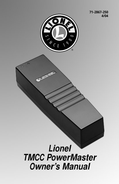
<strong>Lionel</strong><br />
<strong>TMCC</strong> <strong>PowerMaster</strong><br />
Owner’s Manual<br />
<strong>71</strong>-<strong>2867</strong>-<strong>250</strong><br />
4/04
Congratulations!<br />
Congratulations on your purchase of the <strong>Lionel</strong> <strong>TMCC</strong> <strong>PowerMaster</strong>! Designed for use with a<br />
PowerHouse Power Supply, the <strong>TMCC</strong> <strong>PowerMaster</strong> allows you to vary track voltage, change<br />
directions, and operate the whistle and bell sounds on your non-Command locomotives using<br />
your CAB-1 Remote Controller. The <strong>PowerMaster</strong> provides the added safety and convenience of a<br />
circuit breaker and a remote power switch. Use one <strong>PowerMaster</strong> to control each block of track.<br />
Table of contents<br />
Installing the <strong>PowerMaster</strong> and PowerHouse Power Supply 3<br />
Installing your <strong>PowerMaster</strong> with a <strong>Lionel</strong> transformer 4<br />
Assigning an ID number to your <strong>PowerMaster</strong> 5<br />
Operating the <strong>PowerMaster</strong> with conventional (non-Command) locomotives 6<br />
Operating Command-equipped locomotives with the <strong>PowerMaster</strong> 7<br />
Setting the stall voltage 7<br />
Using multiple blocks 8<br />
Troubleshooting 9<br />
FCC Statement 10<br />
Notes 11<br />
Limited Warranty/<strong>Lionel</strong> Service 12<br />
The following <strong>Lionel</strong> marks may be used throughout this instruction manual and are protected under law.<br />
All rights reserved.<br />
<strong>Lionel</strong> ® , TrainMaster ® , Odyssey ® , RailSounds ® , CrewTalk , TowerCom , DynaChuff ,<br />
StationSounds , Pullmor ® , ElectroCoupler , Magne-Traction ® , CAB-1 Remote Controller ® ,<br />
<strong>PowerMaster</strong> ® , <strong>Lionel</strong> ZW ® , ZW ® , PowerHouse ® , <strong>TMCC</strong> ® , <strong>Lionel</strong>ville , Lockon ® , Wireless Tether <br />
The name FasTrack ® is used with permission from Pitsco, Inc.<br />
2
Installing the <strong>PowerMaster</strong> and PowerHouse Power Supply<br />
Your <strong>TMCC</strong> <strong>PowerMaster</strong> receives power from a PowerHouse Power Supply (available<br />
separately, 6-12866 or 6-22983). Follow these steps and refer to Figure 1 as you connect the<br />
power supply.<br />
1. Attach a wire to each of the rails using a <strong>Lionel</strong> Lockon for traditional O-27 and O gauge<br />
users or a FasTrack power terminal section for FasTrack users.<br />
2. Attach the wire connected to the middle rail to the A terminal on the <strong>PowerMaster</strong>.<br />
3. Attach the wire connected to the outside rail to the U terminal on the <strong>PowerMaster</strong>.<br />
4. Insert the Power House Power Supply’s connector plug into the <strong>PowerMaster</strong>’s connector<br />
jack.<br />
5. On the <strong>PowerMaster</strong>, set the power selection switch to 135 or 180 watts, depending on the<br />
type of PowerHouse Power Supply you are using.<br />
6. Plug the PowerHouse Power Supply into a wall outlet (120 volts, 60 Hertz).<br />
7. On the side of the <strong>PowerMaster</strong>, set the RUN/PROGRAM switch to RUN.<br />
8. Set the COMMAND/CONVENTIONAL switch to CONVENTIONAL to operate traditional (non-<br />
Command) locomotives. Set the switch to COMMAND to operate Command-equipped<br />
locomotives.<br />
Note! Track voltage is set to full when the switch is in the COMMAND position.<br />
9. Turn on the PowerHouse Power Supply. At this point, the green light on the <strong>PowerMaster</strong><br />
illuminates to indicate that the <strong>PowerMaster</strong> is receiving power.<br />
Note! Always switch off the PowerHouse Power Supply when you are not operating your<br />
railroad.<br />
Command/Conventional<br />
Switch<br />
Power selection<br />
switch<br />
Program/Run Switch<br />
A<br />
U<br />
135<br />
PROG/RUN CMD/CONV<br />
180<br />
PowerHouse Power<br />
Supply plug<br />
Figure 1. <strong>PowerMaster</strong> installation<br />
3
Installing your <strong>PowerMaster</strong> with a <strong>Lionel</strong> transformer<br />
You may choose to power your <strong>TMCC</strong> <strong>PowerMaster</strong> with any traditional transformer capable<br />
of producing up to 19 volts with a circuit breaker of 7-10 Amps. To make the proper<br />
connections, you need a Power Adapter Cable (available separately, 6-12983). Refer to Figure 2.<br />
1. Connect the Power Adapter Wire fitted with a fuse to the Power/A terminal on your<br />
transformer.<br />
2. Connect the other Power Adapter Wire to the Common/Ground/U terminal on your<br />
transformer.<br />
3. Insert the Power Adapter Wire’s connector plug into the <strong>PowerMaster</strong>’s connector jack.<br />
4. Plug the transformer into a wall outlet (120 volts, 60 Hertz).<br />
5. On the side of the <strong>PowerMaster</strong>, set the switches to RUN and CONVENTIONAL or COMMAND,<br />
depending on whether you will operate Command or conventional locomotives.<br />
Note! It is possible to run Command-equipped locomotives when the switch is in the<br />
CONVENTIONAL position. This is useful for limiting the top speed. Set the voltage<br />
high enough to run you locomotives, then use your CAB-1 Remote Controller to<br />
address locomotive to vary its speed.<br />
6. Set the power selector switch to 135 watts if you are using a transformer with an output of<br />
up to 7.5 Amps or to 180 watts for transformers with outputs of up to 10 Amps. Refer to the<br />
specifications printed on the unit or in the instructions.<br />
7. Turn on the transformer and set the throttle to full power. At this point, the green light on<br />
the <strong>PowerMaster</strong> illuminates to indicate that the <strong>PowerMaster</strong> is receiving power.<br />
Note! Always turn off or unplug your transformer when you are not operating your<br />
railroad.<br />
<strong>TMCC</strong> Power<br />
Adapter Cable<br />
6-12893<br />
A<br />
U<br />
2<br />
POWER<br />
SUPPLY<br />
<strong>Lionel</strong> Lockon<br />
1<br />
Figure 2. Transformer connections<br />
4
Assigning an ID number to your <strong>PowerMaster</strong><br />
Your <strong>PowerMaster</strong> is factory-programmed as track (TR) 1. If you are using a number of<br />
<strong>PowerMaster</strong>s to control different blocks of track, keep in mind that each <strong>PowerMaster</strong> must<br />
have its own ID number. No other product–including Track Power Controllers, multiple<br />
locomotive lash-ups that are addressed as “trains,” or other <strong>PowerMaster</strong>s–can share that ID<br />
number. Assign a unique ID number (any number between 1 and 9) to each <strong>PowerMaster</strong>.<br />
Note! Follow this procedure one unit at a time. Only one PROGRAM/RUN switch should be<br />
in the PROGRAM position at a time.<br />
1. Slide the RUN/PROGRAM switch on the side of the <strong>PowerMaster</strong> to the PROGRAM position.<br />
2. Press TR on your CAB-1 Remote Controller.<br />
3. Use the CAB-1 Remote Controller’s numeric keypad to enter the unique ID number<br />
(from 1 to 9).<br />
4. Press SET under the front panel of the CAB-1 Remote Controller. At this point, the red light<br />
on the <strong>PowerMaster</strong> will flicker to verify your setting.<br />
5. Return the RUN/PROGRAM switch to the RUN position. The <strong>PowerMaster</strong> will operate with<br />
the new ID number until you change it, even if the unit is turned off.<br />
5
Operating the <strong>PowerMaster</strong> with conventional (non-Command)<br />
locomotives<br />
Use your CAB-1 Remote Controller to operate the <strong>PowerMaster</strong>. Press TR and enter the ID<br />
number to select the <strong>PowerMaster</strong> for operation.<br />
Addresses the <strong>PowerMaster</strong>.<br />
Varies track voltage to operate your trains. Turn the throttle clockwise to increase<br />
track voltage, counter-clockwise to decrease it.<br />
Activates the whistle or horn sound effect in locomotives equipped with that<br />
feature. Press the button to begin the sound; release the button to end it.<br />
Starts or stops the bell in any RailSounds sound system-equipped locomotive.<br />
Press the button once to begin the sound, again to stop it.<br />
Sequences your locomotive’s reverse unit to the next operational state.<br />
Provides increased voltage for as long as you press and hold the button. Release<br />
it, and the power returns to the previous level.<br />
Note!<br />
Be sure to use the red throttle knob to set sufficient track voltage.<br />
Reduces voltage for as long as you press and hold the button. Release it, and the<br />
power returns to the previous level.<br />
Immediately stops all <strong>PowerMaster</strong> operations. To resume operations, press TR,<br />
enter the ID number, and turn up the throttle.<br />
Note!<br />
Use HALT only in emergency situations.<br />
Turns off power to the selected track. Turn the throttle to restore power.<br />
L<br />
M<br />
H<br />
Sets the <strong>PowerMaster</strong> to low momentum. Simulates a lighter consist. In this<br />
setting, the locomotive will increase speed faster.<br />
Sets the <strong>PowerMaster</strong> to medium momentum. Simulates a moderately heavy<br />
consist. In this setting, the locomotive will increase speed at a moderate rate.<br />
Sets the <strong>PowerMaster</strong> to high momentum. Simulates a heavier consist. In this<br />
setting, the speed of the locomotive will slowly increase.<br />
Use SET to program the <strong>PowerMaster</strong>’s ID# and stall setting.<br />
6
Operating <strong>TMCC</strong>-equipped locomotives with the <strong>PowerMaster</strong><br />
When operating Command-equipped locomotives with the <strong>PowerMaster</strong>, the <strong>PowerMaster</strong><br />
serves as a circuit breaker and a remote power switch. To operate your Commandequipped<br />
locomotives, you will need to install a <strong>TMCC</strong> Command Base (available separately,<br />
6-12911). Keep in mind that you are actually addressing the Command-equipped locomotive.<br />
The speed of the locomotive may be limited by the voltage setting of the <strong>PowerMaster</strong>, especially<br />
if you are also operating conventional locomotives.<br />
1. Set the COMMAND/CONVENTIONAL switch to COMMAND.<br />
2. Press TR and enter the unique ID number for the <strong>PowerMaster</strong>.<br />
3. Press BOOST to set the track power to full when you are operating a Command-equipped<br />
locomotive and the COMMAND/CONVENTIONAL switch is in the COMMAND position.<br />
Hint!<br />
Note!<br />
You may choose to limit the top speed of your locomotives by reducing the voltage.<br />
Set the COMMAND/CONVENTIONAL switch on the <strong>PowerMaster</strong> to the<br />
CONVENTIONAL position, then set the voltage to your desired maximum speed.<br />
To operate both Command-equipped and conventional locomotives, set the<br />
COMMAND/CONVENTIONAL switch to CONVENTIONAL.<br />
4. Press AUX1, 0 to turn off track power.<br />
Setting the stall voltage<br />
You may choose to set a minimum, or “stall,” voltage to make your locomotives feel more<br />
responsive. The stall voltage is the lowest voltage at which your trains will move.<br />
1. Press TR and enter the unique ID number for the <strong>PowerMaster</strong>.<br />
2. Press SET on the CAB-1 Remote Controller.<br />
3. Adjust the voltage. Increase the voltage until the train begins to move, then reduce the<br />
voltage until the train just comes to a stop.<br />
4. Press SET on the CAB-1 Remote Controller.<br />
The minimum voltage is now set. When you begin to throttle up, the voltage will jump to<br />
this setting. To clear the stall voltage, press TR, enter the ID number, and press SET, SET (two<br />
times).<br />
7
Using multiple blocks<br />
To run multiple conventional (non-Command) locomotives, you will need to create<br />
electrically isolated blocks of track around your layout. Each block will require a separate<br />
<strong>PowerMaster</strong> to vary the track voltage independently.<br />
To create an isolated block of track, you must remove the center pin from both “ends” of the<br />
block. In other words, remove the center pin at the beginning and ending points of the isolated<br />
stretch of track. Replace the steel pins with insulating Fibre Pins (available separately, 6-65041<br />
for O-27 gauge, 6-65543 for O gauge).<br />
Next, connect a <strong>PowerMaster</strong> to each of the blocks. Refer to the first section in this manual<br />
for additional information. We recommend that you plug each PowerHouse Power Supply,<br />
transformer, and <strong>PowerMaster</strong> into the same power strip (available at most hardware and<br />
discount stores).<br />
Finally, be sure that each block of track is “phased” or connected the same way. Perform this<br />
simple test. Start by removing all of your locomotives and powered rolling stock from the track.<br />
Set the COMMAND/CONVENTIONAL switches on each <strong>PowerMaster</strong> to COMMAND for full power.<br />
As illustrated in Figure 3, connect a test light (18-volt bulb) or a voltmeter (available at an<br />
electronics supply store) to the center rails across the insulating pin. If the lights are dim or the<br />
voltmeter shows low AC voltage, the power supplies are properly in phase. If the light is bright or<br />
the voltmeter measures 30 volts or more, reverse the wires at the A and U terminals on one of<br />
the <strong>PowerMaster</strong>s. Repeat this procedure for each isolated block.<br />
Figure 3. Testing for phase<br />
8
Troubleshooting<br />
The green light is off.<br />
• Plug in the PowerHouse Power Supply. Check the PowerHouse Power Supply’s circuit<br />
breaker, and push it in if it has been triggered. Make sure that the PowerHouse Power<br />
Supply’s connector plug is fully plugged into the <strong>PowerMaster</strong> receptacle.<br />
The green light is flashing.<br />
• Check for short circuits and derailments along the track that the <strong>PowerMaster</strong> is controlling.<br />
Reset the <strong>PowerMaster</strong> by pressing BOOST.<br />
The red light doesn’t flash.<br />
• Be sure that there are fresh batteries in the CAB-1 Remote Controller. The Controller should<br />
“beep” each time a button is pressed.<br />
• Extend the antenna completely.<br />
• Be sure that you have addressed the <strong>PowerMaster</strong>. Press TR and enter the unique ID number.<br />
• Press BOOST to reactivate the <strong>PowerMaster</strong>.<br />
• Turn off any interfering electronic devices around your layout, including CBs, radios,<br />
televisions, and computers.<br />
• Relocate the <strong>PowerMaster</strong> around your layout.<br />
• Set a new ID number. To reprogram the unit see page 5.<br />
• Be sure that the frequency crystal is installed with a snug fit.<br />
I want to operate another locomotive on the track (in the Command Control<br />
environment only).<br />
• Address the block of track your locomotive will occupy, pressing TR and entering the ID<br />
number. Deactivate the track by pressing AUX1, 0. Restore power by pressing BOOST.<br />
Track power is set to FULL for Command operations. The stall voltages should be checked as<br />
necessary.<br />
The locomotive will not move.<br />
• Press BOOST or use the red throttle knob to power up the <strong>PowerMaster</strong>.<br />
• Check the connections between the <strong>PowerMaster</strong> and the track. The A terminal goes to the<br />
center rail; the U terminal goes to the outside rail.<br />
• Be sure that there are no derailments. Short circuits will eventually cause the <strong>PowerMaster</strong>’s<br />
circuit breaker to trip. If the unit senses an overload, it waits a moment before shutting<br />
down, allowing you time to fix the problem. If the short circuit remains, the unit will turn<br />
off and the light will flash. Correct the short circuit, then press BOOST to turn on the<br />
<strong>PowerMaster</strong>.<br />
Power is temporarily interrupted.<br />
• The power limit of your <strong>PowerMaster</strong> has been exceeded. Immediately unplug the<br />
<strong>PowerMaster</strong>, then correct any derailment and remove any locomotives or rolling stock that<br />
over-load the system. Plug in the <strong>PowerMaster</strong> and turn on the power supply to resume<br />
operation.<br />
9
FCC Statement<br />
The <strong>TMCC</strong> CAB-1 Remote Controller and the <strong>TMCC</strong> <strong>PowerMaster</strong> comply with Part 15 of the FCC<br />
rules. Operation is subject to the following two conditions: (1) This device may not cause harmful<br />
interference, and (2) this device must accept all interference, including interference that may cause<br />
undesired operation.<br />
Changes or modifications made to the TrainMaster Command Control system that are not expressly<br />
approved by <strong>Lionel</strong> L.L.C. for compliance could void your authority to operate this equipment.<br />
The <strong>TMCC</strong> CAB-1 Remote Controller and the <strong>TMCC</strong> <strong>PowerMaster</strong> have been tested and found to<br />
comply with the limits for Class B digital device and Class C transmitter, pursuant to Part 15 of the<br />
FCC Rules. These limits are designed to provide reasonable protection against harmful interference in<br />
a residential installation. The CAB-1 Remote Controller generates, uses, and can radiate radio<br />
frequency energy and, if not installed and used in accordance with the instructions, may cause<br />
harmful interference to radio communications. However, there is no guarantee that interference will<br />
not occur in a particular installation. If your <strong>TMCC</strong> CAB-1 Remote Controller does cause harmful<br />
interference to radio or television reception (determined by turning the equipment off and on),<br />
correct the interference by trying one or more of the following measures:<br />
• Reorient or relocate the receiving antenna (<strong>PowerMaster</strong>)<br />
• Increase the separation between equipment and receiver<br />
• Connect the equipment into an outlet on a circuit different from that to which the receiver is<br />
connected<br />
• Contact <strong>Lionel</strong> Service for additional information<br />
10
Notes<br />
11
Limited Warranty/<strong>Lionel</strong> Service<br />
T his <strong>Lionel</strong> product, including all mechanical and electrical components, moving parts, motors and<br />
structural components, except for light bulbs, is warranted to the original consumer-purchaser, for one year<br />
against original defects in materials or workmanship when purchased through an authorized <strong>Lionel</strong> merchant.<br />
This warranty does NOT cover normal wear and tear, light bulbs, defects appearing in the course of<br />
commercial use, or damage resulting from abuse or misuse of the product by the purchaser. Transfer of this<br />
product by the original consumer-purchaser to another person voids this warranty. Modification of this product<br />
voids this warranty.<br />
Any warranted product which is defective in original materials or workmanship and is delivered by the<br />
original consumer-purchaser to <strong>Lionel</strong> L.L.C. or an authorized <strong>Lionel</strong> L.L.C. Service Center, together with proof of<br />
original purchase will, at the option of <strong>Lionel</strong> L.L.C., be repaired or replaced, without charge for parts or labor. In<br />
the event the defective product cannot be repaired, and a replacement is not available, a refund of the original<br />
purchase price will be granted. Any products on which warranty service is sought must be sent freight or postage<br />
prepaid, as transportation and shipping charges are not covered by the warranty.<br />
In no event shall <strong>Lionel</strong> L.L.C. be liable for incidental or consequential damages.<br />
Some states do not allow the exclusion or limitation of incidental or consequential damages, so the above<br />
exclusion may not apply to you.<br />
This limited warranty gives you specific legal rights, and you may have other rights which vary from state<br />
to state.<br />
Instructions for Obtaining Service<br />
If service for this <strong>Lionel</strong> L.L.C. product is required, bring the item, along with your dated sales receipt and<br />
completed warranty information to the nearest Authorized <strong>Lionel</strong> Service Center. Your nearest <strong>Lionel</strong> Service<br />
Center can be found by calling 1-800-4-<strong>Lionel</strong>, or by accessing our Website at www.lionel.com.<br />
If you prefer to send your product back to <strong>Lionel</strong> L.L.C. for repair in Michigan, you must first call<br />
586-949-4100 or FAX 586-949-5429, or write to Customer Service, P.O. Box 748, New Baltimore, MI 48047-0748,<br />
stating what the item is, when it was purchased and what seems to be the problem. You will be sent a return<br />
authorization letter and label to ensure your merchandise will be properly handled upon receipt.<br />
Once you have received your return authorization and label, make sure that the item is packed to prevent<br />
damage during shipping and handling. We suggest that you use the product’s original packaging. This<br />
shipment must be prepaid and we recommend that it be insured.<br />
Please make sure you have followed all of the above instructions carefully before returning any<br />
merchandise for service. You may choose to have your product repaired by one of our Authorized <strong>Lionel</strong> Service<br />
Centers after its warranty has expired. A reasonable service fee will be charged.<br />
Warranty Information<br />
Please complete the information below and keep it, along with your dated sales receipt. You must present<br />
this and your dated sales receipt when requesting warranty service.<br />
Name ________________________________________________________________________<br />
Address<br />
______________________________________________________________________<br />
Place of Purchase ________________________________________________________________<br />
Date of Purchase<br />
Product Number<br />
________________________________________________________________<br />
________________________________________________________________<br />
Product Description<br />
______________________________________________________________<br />
©2004 LIONEL L.L.C., CHESTERFIELD, MI 48051-2493<br />
UNITED STATES OF AMERICA<br />
PRINTED IN CHINA


