CW-80 Transformer - Lionel
CW-80 Transformer - Lionel
CW-80 Transformer - Lionel

Create successful ePaper yourself
Turn your PDF publications into a flip-book with our unique Google optimized e-Paper software.
71-4198-251<br />
2/03<br />
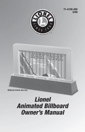
<strong>Lionel</strong><br />
<strong>CW</strong>-<strong>80</strong> <strong>Transformer</strong><br />
Owner’s Manual
Congratulations!<br />
Congratulations on your purchase of the<br />
<strong>Lionel</strong> <strong>CW</strong>-<strong>80</strong> <strong>Transformer</strong>! This device<br />
combines a high output control unit and an<br />
internal power supply, providing your<br />
railroad with <strong>80</strong> watts and 5 amps of<br />
alternating current. With a variable<br />
accessory voltage, the <strong>CW</strong>-<strong>80</strong> <strong>Transformer</strong><br />
features the precision control you demand!<br />
Read this manual thoroughly before<br />
using your <strong>Transformer</strong>. It has important<br />
information on the setup and operation of<br />
this product. If you have any questions after<br />
reviewing these instructions, contact <strong>Lionel</strong><br />
Customer Service at 586-949-4100.<br />
Table of contents<br />
Operating your <strong>CW</strong>-<strong>80</strong> <strong>Transformer</strong> safely 3<br />
Installing your <strong>CW</strong>-<strong>80</strong> <strong>Transformer</strong> 3<br />
Wiring your <strong>CW</strong>-<strong>80</strong> <strong>Transformer</strong> 4-5<br />
Connecting the FasTrack terminal section 6<br />
Operating your trains with the <strong>CW</strong>-<strong>80</strong> <strong>Transformer</strong> 7<br />
Experiencing the features of the <strong>CW</strong>-<strong>80</strong> <strong>Transformer</strong> 7-8<br />
Setting the accessory output 9<br />
Powering your layout with the <strong>CW</strong>-<strong>80</strong> <strong>Transformer</strong> 10<br />
Troubleshooting 11<br />
Limited Warranty/<strong>Lionel</strong> Service 12<br />
The following <strong>Lionel</strong> marks may be used throughout this instruction manual and are protected under<br />
law. All rights reserved.<br />
<strong>Lionel</strong> ® , TrainMaster ® , Odyssey ® , RailSounds , CrewTalk , TowerCom , DynaChuff ,<br />
StationSounds , Pullmor ® , ElectroCoupler , Magne-Traction ® , CAB-1 Remote Controller ® ,<br />
PowerMaster ® , <strong>Lionel</strong> ZW ® , ZW ® , PowerHouse ® , TMCC , <strong>Lionel</strong>ville <br />
The name FasTrack ® is used with permission from Pitso, Inc.<br />
2
Operating your <strong>CW</strong>-<strong>80</strong> <strong>Transformer</strong> safely<br />
Your <strong>Lionel</strong> <strong>CW</strong>-<strong>80</strong> <strong>Transformer</strong> is listed by Underwriter’s Laboratory Inc. and has been<br />
carefully designed to ensure peak performance. When using electrical products, basic<br />
safety precautions should be maintained.<br />
Be sure to observe the following guidelines:<br />
• Read the manual thoroughly before using this device.<br />
• This device is not recommended for children under eight years of age.<br />
• Parents should periodically inspect this product for potential hazards and, if necessary,<br />
have them repaired by an authorized <strong>Lionel</strong> Service Center. In the event that such a<br />
condition exists, the transformer should not be used until it has been properly repaired.<br />
• The <strong>CW</strong>-<strong>80</strong> <strong>Transformer</strong> is intended to be used indoors. Do not use this device if water is<br />
present. Serious or fatal injuries may result.<br />
• Use the <strong>CW</strong>-<strong>80</strong> <strong>Transformer</strong> only for its intended purpose.<br />
• The <strong>CW</strong>-<strong>80</strong> <strong>Transformer</strong> was meant to operate on 120-volt, 60-Hertz power. Do not connect<br />
this product to any other power supply.<br />
• Do not operate the <strong>CW</strong>-<strong>80</strong> <strong>Transformer</strong> with a damaged cord, plug, or case.<br />
• To avoid the risk of electrical shock, do not disassemble the unit. There are no user<br />
serviceable parts inside. If damaged, take this product to an authorized <strong>Lionel</strong> Service<br />
Center. A list of authorized Service Centers is packed with this unit.<br />
• Do not operate the <strong>CW</strong>-<strong>80</strong> <strong>Transformer</strong> on your layout unattended. Obstructed accessories<br />
or stalled trains may overheat, resulting in damage to your layout.<br />
• Always unplug the <strong>CW</strong>-<strong>80</strong> <strong>Transformer</strong> from the power source when not in use.<br />
• Never insert objects into the ventilation slots on this product. Damage to sensitive<br />
electronic components can result.<br />
Installing your <strong>CW</strong>-<strong>80</strong> <strong>Transformer</strong><br />
To mount your <strong>CW</strong>-<strong>80</strong> <strong>Transformer</strong> to your layout or control panel, drive a screw through<br />
each of the four mounting holes located at the corners of the base.<br />
3
Wiring your <strong>CW</strong>-<strong>80</strong> <strong>Transformer</strong><br />
For best performance on large layouts, it is recommended that you use 16-gauge wire to<br />
connect your <strong>CW</strong>-<strong>80</strong> <strong>Transformer</strong> to the track. Use the stripped ends of the wires, banana<br />
plugs, or spade-shaped connectors on all <strong>CW</strong>-<strong>80</strong> <strong>Transformer</strong> connections, with no more than<br />
two wires on each terminal. Terminal strips (available at your local electronics supply store)<br />
allow you to connect multiple wires to evenly distribute power to your layout.<br />
Make sure that all connections are secure. Loose connections can produce extremely high<br />
temperatures. For this reason, do not touch the terminals or track connections during use.<br />
Also, do not locate scenery materials such as lichen or ground foam near the terminals.<br />
Caution! To prevent the excessive build up of heat, be sure to select the proper wire gauge<br />
for your layout. Follow these guidelines:<br />
• Track connections (or Lockon connections) must be made with 18-gauge wire<br />
or heavier. Larger layouts require a minimum of 16-gauge wire.<br />
• Use 24-gauge wire only when connecting single accessories that require lower<br />
current.<br />
• When wiring multiple accessories (two or more) or accessories that require<br />
higher current, be sure to use 18- to 16-gauge wire.<br />
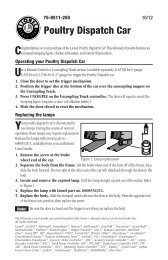
1. Attach a <strong>Lionel</strong> Lockon to your track.<br />
As illustrated in Figure 1, slide the bottom edge of the outside rail into the metal lip on the<br />
Lockon. Press the clip at the end of the Lockon over the bottom edge of the inside rail.<br />
LIONEL<br />
CTC<br />
LOCKON<br />
1<br />
2<br />
Figure 1. Lockon attachment<br />
4
Wiring your <strong>CW</strong>-<strong>80</strong> <strong>Transformer</strong> (continued)<br />
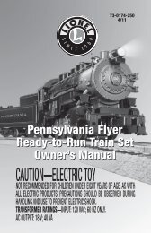
2. Attach one wire to the Lockon spring clip terminal labeled “1” and connect<br />
it to the power terminal labeled “A”. All Controller connections are<br />
illustrated in Figure 2.<br />
To attach the wire to the Lockon, press down on the top of the terminal clip so that a metal<br />
loop is formed. Slide the bare end of the wire into the exposed loop. Release pressure on the<br />
terminal clip, allowing the crimped metal to pinch the end of the wire in the metal loop.<br />
Give a little tug on the wire to check if the hold is secure.<br />
To attach the wire to the <strong>Transformer</strong> terminal, loosen the thumbscrew to expose the hole<br />
in the terminal shaft, then insert the bare end of the wire into the hole. Tighten the<br />
thumbscrew, making sure that the bare wire is in contact with the terminal shaft.<br />
3. Attach a second wire to the Lockon spring clip terminal labeled “2” and<br />
connect it to the power terminal labeled “U”.<br />
4. Attach a third wire to the <strong>Transformer</strong> terminal labeled “B” and connect it<br />
to your accessories.<br />
5. Attach a final wire from your accessories to the <strong>Transformer</strong> terminal<br />
labeled “U”.<br />
6. Plug the <strong>CW</strong>-<strong>80</strong> <strong>Transformer</strong> into your wall outlet (120 volts).<br />
TRACK<br />
ACCESSORY<br />
A<br />
B<br />
U<br />
0~18VAC<br />
0~18VAC<br />
U<br />
120V/60Hz<br />
<br />
Figure 2. Controller connections<br />
0-18 VAC<br />
Variable voltage<br />
to track<br />
5<br />
0-18 VAC<br />
Programmable output<br />
Programmable voltage to<br />
accessories/switches
Connecting the FasTrack terminal section<br />
If you are using the <strong>Lionel</strong> FasTrack track system, you will find that the terminal section<br />
easily connects to the transformer’s TRACK posts. Two wires are attached to the underside of<br />
the FasTrack terminal section (available separately, 6-12016). Attach the spade-shaped<br />
connectors at the ends of these wires to the <strong>CW</strong>-<strong>80</strong> <strong>Transformer</strong>. Be sure that the connections<br />
are secure. Follow these steps and refer to Figure 4.<br />
Caution! If you are connecting the <strong>Transformer</strong> to your layout with any other type of wire,<br />
refer to the guidelines on page 4.<br />
1. Feed the wires through the notch in the FasTrack terminal section. Refer to<br />
Figure 3.<br />
2. Loosen the red TRACK thumbscrew terminal, then slide the spade-shaped<br />
connector at the end of the RED wire into position. The thumbscrew post<br />
should be positioned between the “blades” of the spade connector. Tighten the thumbscrew<br />
to secure the connection.<br />
3. Loosen the black TRACK thumbscrew terminal, then slide the spadeshaped<br />
connector at the end of the BLACK wire into position. Tighten the<br />
thumbscrew to secure the connection.<br />
4. If you need to power an accessory, connect the accessory to the<br />
ACCESSORY thumbscrew terminals.<br />
5. Plug the <strong>CW</strong>-<strong>80</strong> <strong>Transformer</strong> into your wall outlet (120 volts).<br />
FasTrack terminal section<br />
Spade-shaped<br />
connector<br />
TRACK<br />
ACCESSORY<br />
A<br />
B<br />
Notch<br />
Figure 3. <strong>Transformer</strong> connections<br />
U<br />
0~18VAC<br />
0~18VAC<br />
U<br />
120/60z<br />
<br />
6
Operating your trains with the <strong>CW</strong>-<strong>80</strong> <strong>Transformer</strong><br />
You’re clear for departure! Move the throttle control handle forward to increase power to<br />
the track. The farther forward you push the handle, the faster your train will go.<br />
Note! You will notice that the power increases and decreases at a set rate. For example,<br />
quickly throwing the throttle all the way forward will not result in an instant<br />
increase to full power.<br />
When operating in the conventional (non-Command) environment, remember that the<br />
greater the load on the engine (adding more cars for the engine to pull, for example), the<br />
farther forward the handle must be pushed before it will operate the locomotive.<br />
Experiencing the features of the <strong>CW</strong>-<strong>80</strong> <strong>Transformer</strong><br />
Refer to Figure 4 on page 8 for the location of the <strong>Transformer</strong> features listed in this<br />
section.<br />
THROTTLE<br />
Push the throttle forward to increase track power. The markings on the throttle<br />
approximate the percentage of full power. For more realism, push the throttle slowly to<br />
gradually increase or decrease the speed of the locomotive. Slowing or stopping the locomotive<br />
with the throttle instead of the DIRECTION button will allow you to continue in the same<br />
direction when you increase the throttle again. To achieve this effect, reduce the throttle to the<br />
point that the locomotive stops moving, don’t completely turn off the throttle. That way, your<br />
train won’t sequence into neutral.<br />
POWER-ON INDICATOR<br />
The green light will remain on during normal operation. The green light will begin to<br />
flash if you exceed the power limit of the <strong>Transformer</strong>. The unit will allow you to momentarily<br />
exceed the power limit, but power will be gradually reduced until the problem is corrected.<br />
This safety feature replaces the circuit breaker. The benefit is that the <strong>Transformer</strong> will not<br />
instantly turn off.<br />
DIRECTION<br />
The DIRECTION control button interrupts track power to activate the reverse unit in<br />
locomotives with forward-neutral-reverse operation. This button has no effect on locomotives<br />
not equipped with reverse units or on locomotives with the reverse unit in the OFF position.<br />
WHISTLE/HORN<br />
The WHISTLE/HORN button will activate <strong>Lionel</strong> sound-equipped locomotives, including<br />
those equipped with the RailSounds sound system. The sound will continue until the button is<br />
released. No external sound activation buttons are needed.<br />
7
Experiencing the features of the <strong>CW</strong>-<strong>80</strong> <strong>Transformer</strong> (continued)<br />
BELL<br />
The BELL button will activate all RailSounds bells. Press and hold the BELL button for two<br />
to three seconds to begin the sounds; press and hold the button again to turn off the ringing.<br />
Note! Do not activate horns, whistles, or bells on RailSounds-equipped locomotives until<br />
track power has been turned on for a few moments, or a continuous horn/whistle or<br />
bell sound may occur. To correct this problem, simply turn off the <strong>CW</strong>-<strong>80</strong><br />
<strong>Transformer</strong>, then turn it back on.<br />
Note!<br />
The <strong>CW</strong>-<strong>80</strong> <strong>Transformer</strong> may cause random whistles in the <strong>Lionel</strong> Mighty Sounds of<br />
Steam TM tenders with a three-pin connector. We recommend that you a purchase a<br />
RailSounds-equipped tender to solve this problem.<br />
Power-on indicator<br />
The green light<br />
illuminates when the<br />
<strong>CW</strong>-<strong>80</strong> is on.<br />
Direction<br />
Press the DIRECTION button to go forward<br />
or reverse, or to place the locomotive in<br />
“neutral” (no movement, headlight is on).<br />
Bell<br />
Starts or stops the tolling bell in any<br />
Railsounds-equipped locomotive.<br />
Press BELL to begin the sound,<br />
again to stop it.<br />
Whistle/Horn<br />
Activates the whistle or horn sound<br />
effect in your <strong>Lionel</strong> locomotives. Press<br />
WHISTLE/HORN to begin the sound;<br />
release the button to end it.<br />
Figure 4. <strong>Transformer</strong> features<br />
Throttle<br />
Controls your locomotive’s speed. Throw the<br />
throttle forward to increase locomotive speed,<br />
backward to slow it down.<br />
8
Setting the accessory output<br />
Take control of your <strong>Lionel</strong> empire with your <strong>CW</strong>-<strong>80</strong> <strong>Transformer</strong>! You choose how much<br />
power your accessories need. Your <strong>CW</strong>-<strong>80</strong> <strong>Transformer</strong> features a programmable accessory<br />
output. The ability to control the voltage allows you to set the speed of your accessory motors<br />
and the intensity of your lights. Follow these steps to set the voltage.<br />
Note!<br />
The accessory voltage was set to 12 volts at the factory.<br />
1. Bring the throttle all the way back to turn off the power.<br />
2. Press and hold down the DIRECTION, WHISTLE/HORN, and BELL buttons<br />
on the Controller. Refer to Figure 4 for the location of these buttons.<br />
The green light on the <strong>Transformer</strong> will flash and track power will turn off.<br />
3. With all three buttons held down, raise the throttle slowly until you reach<br />
your desired accessory voltage.<br />
4. Release the buttons once you have reached your desired voltage.<br />
The accessory turns off, and the solid green light indicates that you have set the accessory<br />
voltage.<br />
5. Bring the throttle all the way back to turn off the power.<br />
The voltage will momentarily increase, briefly causing the lights to shine brighter or the<br />
motors to operate faster, before returning to the set level.<br />
At this point, increasing the throttle again will control track power.<br />
9
Powering your layout with the <strong>CW</strong>-<strong>80</strong> <strong>Transformer</strong><br />
Your <strong>CW</strong>-<strong>80</strong> <strong>Transformer</strong> provides a total output of five amps. The track outputs will deliver<br />
all of this power to the track when no accessories are connected to the <strong>Transformer</strong>. Keep<br />
in mind that connected accessories borrow some of this power. For example, if the accessories<br />
require two amps of the total five-amp capacity of the <strong>Transformer</strong>, you have three amps<br />
available for track power. This built-in flexibility will provide power for virtually any small- to<br />
medium-sized railroad. Also, available voltage depends on how much load is on the two<br />
outputs. Generally, track voltage and accessory voltage are 0-16 volts (AC) each.<br />
This <strong>Transformer</strong> is capable of operating trains up to and including dual-motored AC<br />
engines. To operate at this level of track power, it may be necessary to disconnect any<br />
accessories. You may also want to attempt to lower the accessory voltage settings. Refer to the<br />
“Setting the accessory output” section.<br />
You may momentarily approach or exceed the five-amp limit of the <strong>CW</strong>-<strong>80</strong> <strong>Transformer</strong><br />
when pulling illuminated cars, fighting over grades with heavy loads, or operating accessories.<br />
When you reach five amps, the green light on the Controller will begin to flash. This indicates<br />
that the <strong>Transformer</strong> is in “fold-back mode.” In fold-back mode, the <strong>Transformer</strong> is<br />
automatically reducing, or folding back, power. This gradual reduction in power provides<br />
interruption-free power while bringing the amperage back down to a safe level.<br />
10
Troubleshooting<br />
No lights or operation<br />
Be sure <strong>CW</strong>-<strong>80</strong> <strong>Transformer</strong> is plugged in.<br />
Train runs, but WHISTLE/HORN, BELL, and DIRECTION buttons do not work<br />
Check track connections. The track must be connected to the “A” and “U” terminals on the<br />
<strong>Transformer</strong>.<br />
No change when DIRECTION button is pressed<br />
Be sure that your locomotive reverse unit switch is ON.<br />
Accessory operation is intermittent or absent<br />
Check for loose, shorted, or improper connections. The accessory output voltage may have<br />
been set too low for the accessory. Refer to page 9 and reset the voltage to a higher level.<br />
Locomotive runs slowly or lights dim at the far end of the track<br />
On larger layouts, additional track resistance may cause a voltage drop. Attach additional<br />
Lockons to the remote portion of your track.<br />
Green light begins to flash<br />
The power limit of the <strong>Transformer</strong> has been exceeded. The unit will gradually reduce power<br />
until the problem is corrected.<br />
Bell button blows whistle<br />
Switch the wire connections at the Lockon or Controller Terminals. Be sure that the U post is<br />
connected to the outside rail and the A post is connected to the inside rail.<br />
11
Limited Warranty/<strong>Lionel</strong> Service<br />
This <strong>Lionel</strong> product, including all<br />
mechanical and electrical components,<br />
moving parts, motors and structural<br />
components, except for light bulbs, is warranted<br />
to the original consumer-purchaser, for one year<br />
against original defects in materials or<br />
workmanship when purchased through an<br />
authorized <strong>Lionel</strong> merchant.<br />
This warranty does NOT cover normal wear<br />
and tear, light bulbs, defects appearing in the<br />
course of commercial use, or damage resulting<br />
from abuse or misuse of the product by the<br />
purchaser. Transfer of this product by the original<br />
consumer-purchaser to another person voids this<br />
warranty. Modification of this product voids this<br />
warranty.<br />
Any warranted product which is defective in<br />
original materials or workmanship and is<br />
delivered by the original consumer-purchaser to<br />
<strong>Lionel</strong> L.L.C. or an authorized <strong>Lionel</strong> L.L.C. Service<br />
Center, together with proof of original purchase<br />
will, at the option of <strong>Lionel</strong> L.L.C., be repaired or<br />
replaced, without charge for parts or labor. In the<br />
event the defective product cannot be repaired, and<br />
a replacement is not available, a refund of the<br />
original purchase price will be granted. Any<br />
products on which warranty service is sought must<br />
be sent freight or postage prepaid, as<br />
transportation and shipping charges are not<br />
covered by the warranty.<br />
In no event shall <strong>Lionel</strong> L.L.C. be<br />
liable for incidental or<br />
consequential damages.<br />
Some states do not allow the exclusion or<br />
limitation of incidental or consequential damages,<br />
so the above exclusion may not apply to you.<br />
This limited warranty gives you specific legal<br />
rights, and you may have other rights which vary<br />
from state to state.<br />
Instructions for Obtaining Service<br />
If service for this <strong>Lionel</strong> L.L.C. product is<br />
required, bring the item, along with your dated<br />
sales receipt and completed warranty information<br />
to the nearest Authorized <strong>Lionel</strong> Service Center.<br />
Your nearest <strong>Lionel</strong> Service Center can be found<br />
by calling 1-<strong>80</strong>0-4-<strong>Lionel</strong>, or by accessing our<br />
Website at www.lionel.com.<br />
If you prefer to send your product back to<br />
<strong>Lionel</strong> L.L.C. for repair in Michigan, you must<br />
first call 586-949-4100 or FAX 586-949-5429, or<br />
write to Customer Service, P.O. Box 748, New<br />
Baltimore, MI 4<strong>80</strong>47-0748, stating what the item<br />
is, when it was purchased and what seems to be<br />
the problem. You will be sent a return<br />
authorization letter and label to ensure your<br />
merchandise will be properly handled upon<br />
receipt.<br />
Once you have received your return<br />
authorization and label, make sure that the item<br />
is packed to prevent damage during shipping and<br />
handling. We suggest that you use the product’s<br />
original packaging. This shipment must be<br />
prepaid and we recommend that it be insured.<br />
Please make sure you have followed all of the<br />
above instructions carefully before returning any<br />
merchandise for service. You may choose to have<br />
your product repaired by one of our Authorized<br />
<strong>Lionel</strong> Service Centers after its warranty has<br />
expired. A reasonable service fee will be charged.<br />
Warranty Information<br />
Please complete the information below and<br />
keep it, along with your dated sales receipt. You<br />
must present this and your dated sales receipt<br />
when requesting warranty service.<br />
Name<br />
____________________________<br />
Address ____________________________<br />
Place of Purchase<br />
Date of Purchase<br />
____________________<br />
____________________<br />
Product Number ______________________<br />
Product Description____________________<br />
©2003 LIONEL L.L.C., CHESTERFIELD, MI 4<strong>80</strong>51-2493<br />
UNITED STATES OF AMERICA<br />
PRINTED IN U.S.A.