Three-dimensional imaging and cone beam volume CT in C-arm ...
Three-dimensional imaging and cone beam volume CT in C-arm ...
Three-dimensional imaging and cone beam volume CT in C-arm ...

You also want an ePaper? Increase the reach of your titles
YUMPU automatically turns print PDFs into web optimized ePapers that Google loves.
Diagn Interv Radiol 2005; 11:10-13<br />
© Turkish Society of Radiology 2005<br />
GENERAL RADIOLOGY<br />
TECHNICAL NOTE<br />
<strong>Three</strong>-<strong>dimensional</strong> <strong>imag<strong>in</strong>g</strong> <strong>and</strong> <strong>cone</strong> <strong>beam</strong><br />
<strong>volume</strong> <strong>CT</strong> <strong>in</strong> C-<strong>arm</strong> angiography with flat panel<br />
detector<br />
Serg<strong>in</strong> Akpek, Thomas Brunner, Goetz Benndorf, Charles Strother<br />
ABSTRA<strong>CT</strong><br />
We evaluated a new 3D angiography system with a<br />
flat panel detector (FPD) for its capabilitiy to acquire<br />
<strong>volume</strong> sets dur<strong>in</strong>g a s<strong>in</strong>gle rotation scan <strong>and</strong> to<br />
reconstruct high spatial resolution three-<strong>dimensional</strong><br />
<strong>and</strong> cross sectional images, namely <strong>cone</strong> <strong>beam</strong><br />
<strong>volume</strong> computed tomography (CBV<strong>CT</strong>) images.<br />
Present status of the technique, advantages <strong>and</strong><br />
potential applications are discussed.<br />
Key words: • angiography • tomography, X-ray<br />
computed • <strong>imag<strong>in</strong>g</strong>, three <strong>dimensional</strong><br />
<strong>Three</strong>-<strong>dimensional</strong> (3D) rotational angiography basically uses the<br />
same <strong>imag<strong>in</strong>g</strong> technique with <strong>cone</strong> <strong>beam</strong> <strong>volume</strong> computed tomography<br />
(CBV<strong>CT</strong>). It is the rotational <strong>volume</strong> scann<strong>in</strong>g with<br />
two-<strong>dimensional</strong> X-ray detector <strong>and</strong> <strong>cone</strong> shaped X-ray <strong>beam</strong>. This technique<br />
has been ma<strong>in</strong>ly used for the high contrast structures such as contrast<br />
medium filled vascular structures. Application of flat panel detector<br />
(FPD) technology to the C-<strong>arm</strong> systems may improve the image quality<br />
<strong>in</strong> both contrast <strong>and</strong> spatial resolution. Acquir<strong>in</strong>g cross-sectional <strong>and</strong> 3D<br />
images by a simple C-<strong>arm</strong> system dur<strong>in</strong>g percutaneous, endovascular or<br />
open surgical procedures with high spatial <strong>and</strong> contrast resolution can<br />
be very helpful not only to detect the unfortunate complications, but<br />
also to better underst<strong>and</strong> complex anatomy.<br />
Technique<br />
System<br />
In animal laboratory, two <strong>dimensional</strong> rotational projection radiographs<br />
were acquired by us<strong>in</strong>g a s<strong>in</strong>gle plane C-<strong>arm</strong> angiography system<br />
with a 18×18 cm amorphous silicon FPD (AXIOM Artis dFC, Siemens<br />
Medical Solutions, Germany). System software is a patched version <strong>and</strong><br />
not released for cl<strong>in</strong>ical usage. Acquired images were then transferred<br />
to a dedicated post-process<strong>in</strong>g workstation (Leonardo, Siemens Medical<br />
Solutions, Germany) where a <strong>volume</strong> data set was reconstructed <strong>in</strong> a <strong>CT</strong><br />
type data set consist<strong>in</strong>g of many sections with the thickness of voxel size<br />
<strong>and</strong> visualized with <strong>volume</strong> render<strong>in</strong>g technique as 3D <strong>and</strong> multi-planar<br />
reconstruction images. The whole data acquisition is called 3D-Dyna.<br />
From the Department of Radiology (S.A. *), Gazi University<br />
School of Medic<strong>in</strong>e, Ankara, Turkey; the Department of<br />
Radiology (G.B., C.S.), the Methodist Hospital, Houston,<br />
Texas, USA; <strong>and</strong> Siemens Medical Solutions (T.B.), Forchheim,<br />
Germany.<br />
Received 20 April 2004; revision requested 20 July 2004;<br />
revision received 19 October 2004; accepted 14 November 2004.<br />
Data acquisition<br />
Basically two different <strong>imag<strong>in</strong>g</strong> protocols were available for so-called<br />
3D-Dyna with different rotation times, numbers of images acquired<br />
dur<strong>in</strong>g each rotation. C-<strong>arm</strong> makes a s<strong>in</strong>gle rotation around the z-axis<br />
of the object, <strong>in</strong> contrary to double rotation <strong>in</strong> 3D-DSA (mask <strong>and</strong> fill<br />
runs). In the 5-second run, rotation angle was 200 0 with 1.5 0 <strong>in</strong>crement<br />
reveal<strong>in</strong>g 133 projections. Rotation speed was 40 0 /s <strong>and</strong> frame rate was<br />
26.6 frame/s. In the 11-second run, these parameters were 220 0 , 0.8 0 ,<br />
273, 20 0 /s <strong>and</strong> 24.8, respectively. There were also two different dose sett<strong>in</strong>gs<br />
for both 5- <strong>and</strong> 11-second data acquisition protocols. The system<br />
dose (at the entrance of the detector) for low <strong>and</strong> high dose sett<strong>in</strong>gs<br />
were 0.36 mGy/F <strong>and</strong> 1.2 mGy/F, respectively. Zoom sett<strong>in</strong>gs could<br />
also be changed, but the system was calibrated only for the zoom 0 (25<br />
cm). The matrix of the FPD system was 1.024×1.024 (useful matrix was<br />
960×960) <strong>and</strong> the pixel size was 0.184 (all technical <strong>in</strong>formation are<br />
unpublished data from the manufacturer).<br />
CBV<strong>CT</strong> 3D image reconstruction method uses a modified well-known<br />
Feldkamp reconstruction algorithm (1, 2).<br />
10
a<br />
c<br />
b<br />
d<br />
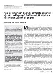
to high quality cross-sectional images<br />
<strong>and</strong> 3D reconstruction of the cervical<br />
sp<strong>in</strong>e, we could also differentiate the<br />
carotid vascular lumen <strong>and</strong> embolic<br />
material with<strong>in</strong> the aneurysm <strong>and</strong><br />
their relationship on the cross-sectional<br />
images of 3D-Dyna with 20% contrast<br />
<strong>in</strong>jection after the embolization<br />
(Figure 1). Images of the dog cranium<br />
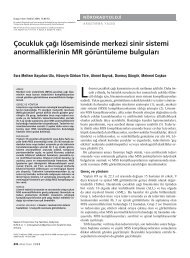
also had high spatial resolution. Truncation<br />
artifacts had occurred because<br />
the sizes of the dog’s cranium were bigger<br />
than the field of view. Image quality<br />
for the bony structures, even for the<br />
complex ones such as the temporal<br />
bone, was sufficient for diagnostic<br />
purposes. However, <strong>in</strong>tra-cranial soft<br />
tissue structures or the compartments<br />
could not be differentiated (Figure 2).<br />
3D-Dyna study of the human volunteer<br />
revealed good quality axial <strong>and</strong><br />
3D images of the bony structures at the<br />
wrist. Although the contrast resolution<br />
was lower compared to <strong>CT</strong>, differentiation<br />
of muscle, tendon <strong>and</strong> fat tissue<br />
was possible (Figure 3).<br />
e<br />
Figure 1. Experimental aneurysm created on the right common carotid artery <strong>in</strong> a dog was<br />
embolized with a liquid embolic agent. Post-embolization 3D DSA (a), post-embolization<br />
3D-Dyna with 20% contrast (b) are seen <strong>and</strong>, as it is not a subtracted image, neighbor<strong>in</strong>g<br />
structures such as cervical sp<strong>in</strong>e can also be evaluated (c-f). Orthogonal cross-sectional<br />
images (c: oblique sagittal, d: axial, e: oblique coronal) reconstructed after 3D-Dyna<br />
acquisition with 20% contrast reveal the relationship between the embolic material<br />
(arrows) <strong>and</strong> the carotid lumen (arrowheads). Axial image (d) shows normal common<br />
carotid artery (arrowhead).<br />
Image data sets for 3D-Dyna were<br />
acquired <strong>in</strong> five dogs that were studied<br />
under a different research protocol <strong>and</strong><br />
from a human volunteer. Cranial <strong>and</strong><br />
neck regions were studied <strong>in</strong> dogs <strong>and</strong><br />
elbow region was chosen due to its<br />
complex bony anatomy <strong>and</strong> size for<br />
f<br />
the human volunteer. Experimental<br />
sidewall aneurysms were created <strong>and</strong><br />
embolized with a liquid embolic agent<br />
<strong>in</strong> all of the animals. 3D-DSA <strong>and</strong> 3D-<br />
Dyna <strong>imag<strong>in</strong>g</strong> for the neck region <strong>and</strong><br />
additional 3D-Dyna acquisition for the<br />
cranium were performed. In addition<br />
Discussion<br />
CBV<strong>CT</strong> has been <strong>in</strong>vestigated <strong>in</strong> the<br />
past two decades to evaluate its potential<br />
advantages over a fan <strong>beam</strong> <strong>CT</strong> like<br />
improved data acquisition efficiency,<br />
uniform <strong>and</strong> <strong>in</strong>creased spatial resolution<br />
<strong>and</strong> better 3D <strong>CT</strong> applications.<br />
The recent development of X-ray flat<br />
panel detectors (FPD) has made CB-<br />
V<strong>CT</strong> <strong>imag<strong>in</strong>g</strong> feasible for practical use<br />
<strong>in</strong> a cl<strong>in</strong>ical sett<strong>in</strong>g. Other slow-rotat<strong>in</strong>g<br />
systems without a gantry or C-<strong>arm</strong><br />
design have started to be tested <strong>in</strong> the<br />
maxillofacial region <strong>and</strong> for breast <strong>imag<strong>in</strong>g</strong><br />
(3, 4).<br />
<strong>Three</strong>-<strong>dimensional</strong> computed rotational<br />
angiography, orig<strong>in</strong>ally developed<br />
for vascular <strong>imag<strong>in</strong>g</strong>, has ga<strong>in</strong>ed<br />
a high level of acceptance among the<br />
<strong>in</strong>terventional neuroradiologists (5).<br />
<strong>Three</strong>-<strong>dimensional</strong> reconstructions<br />
allow a better underst<strong>and</strong><strong>in</strong>g of the<br />
complex vascular pathologies <strong>and</strong><br />
their anatomical relationship with<br />
other important vascular or surround<strong>in</strong>g<br />
structures. The necessary data for<br />
reconstruction of 2D digital projection<br />
images can also be collected<br />
dur<strong>in</strong>g rotational angiography without<br />
DSA. Volume scann<strong>in</strong>g with 2D<br />
detector <strong>and</strong> <strong>cone</strong> <strong>beam</strong> x-ray yields<br />
isotropic voxel size <strong>and</strong> image spatial<br />
resolution. As a result, multi-planar<br />
high-resolution cross-sectional <strong>and</strong><br />
3D reconstructions can be obta<strong>in</strong>ed.<br />
Volume 11 • Issue 1<br />
<strong>Three</strong>-<strong>dimensional</strong> <strong>imag<strong>in</strong>g</strong> <strong>and</strong> <strong>cone</strong> <strong>beam</strong> <strong>volume</strong> <strong>CT</strong> <strong>in</strong> C-<strong>arm</strong> angiography • 11
a<br />
c<br />
Figure 2. 3D-Dyna <strong>imag<strong>in</strong>g</strong> of a dog’s cranium. a. <strong>Three</strong>-<strong>dimensional</strong> reconstruction show<strong>in</strong>g<br />
the cranium <strong>and</strong> part of the m<strong>and</strong>ible from anteroposterior view. In axial (b) <strong>and</strong> coronal (c)<br />
cross-sectional images, differentiation of the bra<strong>in</strong> parenchyma from ventricles or subarachnoid<br />
space is not possible due to low contrast resolution. Magnified axial view at the level of the left<br />
temporal bone (d) demonstrates middle ear ossicles <strong>and</strong> <strong>in</strong>ner ear structures with high spatial<br />
resolution.<br />
Image <strong>in</strong>tensifier or FPDs can be used<br />
as a detector. FPDs have been shown<br />
to yield higher spatial resolution than<br />
the image <strong>in</strong>tensifier detectors (6). Isotropic<br />
scann<strong>in</strong>g voxel size lead<strong>in</strong>g to<br />
true isotropic spatial resolution is an<br />
<strong>in</strong>herent <strong>and</strong> major advantage of FPDbased<br />
<strong>cone</strong> <strong>beam</strong> tomographic <strong>imag<strong>in</strong>g</strong>.<br />
True isotropic spatial resolution<br />
still cannot be achieved even with<br />
the state-of-the-art 16-slice spiral <strong>CT</strong><br />
systems. Longitud<strong>in</strong>al <strong>and</strong> <strong>in</strong>-plane<br />
resolution that can be achieved with<br />
such systems are 0.6 mm <strong>and</strong> 0.5 mm,<br />
respectively (7). However, spatial resolution<br />
<strong>in</strong> a comparable custom-made<br />
system with a FPD at a pixel size of<br />
0.254 mm was reported as 0.35 mm<br />
(6). The system that we used has a<br />
spatial resolution of 0.20 mm (manufacturer’s<br />
data). Actually, hav<strong>in</strong>g a<br />
<strong>volume</strong> data set with a true isotropic<br />
12 • March 2005 • Diagnostic <strong>and</strong> Interventional Radiology<br />
b<br />
d<br />
resolution makes two different resolution<br />
def<strong>in</strong>itions (axial or <strong>in</strong>-plane <strong>and</strong><br />
longitud<strong>in</strong>al or z-plane) unnecessary.<br />
As a result, traditional axial slice may<br />
lose its importance. Instead, <strong>in</strong>teractive<br />
view<strong>in</strong>g <strong>and</strong> manipulation of<br />
isotropic <strong>volume</strong> images <strong>and</strong> film<strong>in</strong>g<br />
the selected stored images will be the<br />
rout<strong>in</strong>e radiological practice. Furthermore,<br />
one can expect improvement <strong>in</strong><br />
image quality with FPD because of the<br />
follow<strong>in</strong>g reasons: FPD has no image<br />
distortions like <strong>in</strong> the image <strong>in</strong>tensifiers<br />
<strong>in</strong>fluenced by the Earth’s magnetic<br />
field. The higher bit depth (14<br />
vs. 12) may be transferred <strong>in</strong>to higher<br />
detection dynamics <strong>and</strong> they are also<br />
less sensitive to over exposure, which<br />
causes a glar<strong>in</strong>g or bloom<strong>in</strong>g effect on<br />
image <strong>in</strong>tensifier systems. Higher detective<br />
quantum efficiency may also<br />
lead to better dose usage.<br />
Although sophisticated tools <strong>in</strong><br />
the era of endovascular surgery<br />
have been developed, procedure related<br />
complications such as vessel<br />
rupture <strong>in</strong> aneurysm treatment, are<br />
still important causes that <strong>in</strong>crease<br />
mortality <strong>and</strong> morbidity. Sometimes<br />
vessel rupture can be very obvious<br />
dur<strong>in</strong>g the angiography <strong>and</strong> one<br />
can easily see the extravasations of<br />
contrast medium. In other cases, it<br />
can be detected by unexpected shift<br />
of the vascular structures by acutely<br />
develop<strong>in</strong>g hematoma, while m<strong>in</strong>or<br />
perforation <strong>and</strong> subsequent self-limited<br />
subarachnoid bleed<strong>in</strong>g can easily<br />
be overlooked. This situation can<br />
be the cause of the worsen<strong>in</strong>g of the<br />
patient’s condition after an otherwise<br />
uneventful endovascular procedure. A<br />
cross-sectional <strong>imag<strong>in</strong>g</strong> method with<br />
a high spatial <strong>and</strong> contrast resolution,<br />
readily available <strong>in</strong> angiography suites<br />
<strong>and</strong> allow<strong>in</strong>g <strong>imag<strong>in</strong>g</strong> of the <strong>in</strong>tracranial<br />
bra<strong>in</strong> parenchyma, subarachnoid<br />
space <strong>and</strong> ventricular system, can be<br />
very helpful <strong>in</strong> such undeterm<strong>in</strong>ed<br />
situations. Further therapeutic measures<br />
can be tailored accord<strong>in</strong>g to the<br />
result. Prompt patient transfer from<br />
angiography suite to the operat<strong>in</strong>g<br />
room would save very precious time<br />
for the complicated patients. Other<br />
advantages of comb<strong>in</strong>ed systems (angio-<strong>CT</strong>)<br />
are also valid for the discussed<br />
system. For example, cross-sectional<br />
<strong>and</strong> 3D bone images, <strong>in</strong> addition to<br />
fluoroscopic images, would be very<br />
beneficial for the sp<strong>in</strong>al <strong>in</strong>terventional<br />
procedures. This is actually the<br />
same rationale that those comb<strong>in</strong>ed<br />
systems evolved from.<br />
C-<strong>arm</strong> based or different design CB-<br />
V<strong>CT</strong> systems have great advantages <strong>in</strong><br />
<strong>imag<strong>in</strong>g</strong> of trauma cases or <strong>in</strong> orthopedic<br />
surgery operat<strong>in</strong>g room. Acquir<strong>in</strong>g<br />
3D <strong>and</strong> cross-sectional images <strong>in</strong><br />
addition to conventional 2D images<br />
with the same system certa<strong>in</strong>ly gives<br />
a chance to physician to better underst<strong>and</strong><br />
fractures <strong>and</strong> results of their<br />
therapeutic reconstructive attempts<br />
on bony structures. Similar work has<br />
been done by El-Sheik et al. <strong>and</strong> is<br />
called computed rotational osteography<br />
(8).<br />
The problem related to the geometry<br />
of the x-ray <strong>beam</strong> appears at the image<br />
reconstruction level. Cone <strong>beam</strong> <strong>and</strong><br />
streak artifacts may decrease the image<br />
quality <strong>and</strong> contrast resolution,<br />
but at the quality level that has been<br />
Akpek et al.
a<br />
c<br />
b<br />
d<br />
the 11-second (high dose) acquisition<br />
with medium field of view <strong>and</strong><br />
256×256×256 image reconstruction<br />
matrix <strong>in</strong>clud<strong>in</strong>g the data transfer.<br />
With the cont<strong>in</strong>uous improvement<br />
<strong>in</strong> computer technology, this would<br />
probably decrease significantly <strong>in</strong><br />
near future.<br />
Although the acquired cross-sectional<br />
<strong>and</strong> 3D images were <strong>in</strong> good<br />
quality with high spatial resolution,<br />
further studies <strong>in</strong> phantoms, animals<br />
<strong>and</strong> patients should be conducted<br />
to validate the technique for cl<strong>in</strong>ical<br />
applications. We believe cl<strong>in</strong>ical<br />
practice will extend the limits of the<br />
application spectrum of this <strong>imag<strong>in</strong>g</strong><br />
technology.<br />
Figure 3. Sagittal (a), axial (b) <strong>and</strong> coronal (c) cross-sectional images reconstructed after 3D-<br />
Dyna acquisition from a human wrist. High spatial resolution gives good quality bone images.<br />
Contrast resolution is good enough to differentiate muscle <strong>and</strong> tendons (asterisk) from the fat<br />
tissue (arrows). d. <strong>Three</strong>-<strong>dimensional</strong> reconstruction of the same anatomic region del<strong>in</strong>eates<br />
complex bony anatomy.<br />
achieved with the present setup, <strong>cone</strong><br />
artifacts play no significant role. FPD<br />
system has an advantage on image<br />
<strong>in</strong>tensifier systems <strong>in</strong> contrast resolution<br />
parameters especially at lower<br />
doses with<strong>in</strong> cl<strong>in</strong>ical range (6), but,<br />
nonetheless, we still could not differentiate<br />
bra<strong>in</strong> tissue, ventricular system<br />
<strong>and</strong> subarachnoid space <strong>in</strong> dogs with<br />
our system. With 273 projections, the<br />
number of streak artifacts limits the<br />
contrast resolution. The streak artifact<br />
level will improve as soon as there<br />
will be protocols available with more<br />
projections. Obviously, temporal resolution<br />
of the system is not comparable<br />
to the multi-slice <strong>CT</strong> due to the relatively<br />
slow C-<strong>arm</strong> motion. We th<strong>in</strong>k<br />
that the low temporal resolution does<br />
not significantly affect the potential<br />
cl<strong>in</strong>ical benefits <strong>and</strong> applications of<br />
a C-<strong>arm</strong> based <strong>cone</strong> <strong>beam</strong> <strong>CT</strong> method<br />
<strong>in</strong> skeletal system or <strong>in</strong> <strong>in</strong>terventional<br />
radiology procedures.<br />
Major limitation of the currently<br />
available system used <strong>in</strong> this study is<br />
the small field of view. Large objects<br />
cause truncation artifact <strong>in</strong> crosssectional<br />
images but it can easily be<br />
overcome by <strong>in</strong>creas<strong>in</strong>g the size of the<br />
FPD. Total time necessary to acquire<br />
the data set <strong>and</strong> image reconstruction<br />
depends on the protocol details,<br />
but it was around five m<strong>in</strong>utes for<br />
References<br />
1. Wiesent K, Barth K, Navab N, Durlak<br />
P, Brunner T, Schuetz O, Seissler W.<br />
Enhanced 3D-reconstruction algorithm for<br />
C-<strong>arm</strong> systems suitable for <strong>in</strong>terventional<br />
procedures. IEEE Trans Med Imag<strong>in</strong>g 2000;<br />
19:391-403.<br />
2. Feldkamp LA, Davis LC, Kress JW. Practical<br />
<strong>cone</strong>-<strong>beam</strong> algorithm. J Opt Soc Am 1984;<br />
1:612-619.<br />
3. Sukovic P. Cone <strong>beam</strong> computed tomography<br />
<strong>in</strong> craniofacial <strong>imag<strong>in</strong>g</strong>. Orthod<br />
Craniofacial Res 2003; 6(Suppl. 1):31-36.<br />
4. Boone JM, Nelson TR, L<strong>in</strong>dfors KK, Seibert<br />
JA. Dedicated breast <strong>CT</strong>: radiation dose<br />
<strong>and</strong> image quality evaluation. Radiology<br />
2001; 221:657-667.<br />
5. Fahrig R, Fox AJ, Lownie S, Holdsworth<br />
DW. Use of a C-<strong>arm</strong> system to generate<br />
true three-<strong>dimensional</strong> computed rotational<br />
angiograms: prelim<strong>in</strong>ary <strong>in</strong> vitro<br />
<strong>and</strong> <strong>in</strong> vivo results. AJNR Am J Neuroradiol<br />
1997; 18:1507-1514.<br />
6. Baba R, Konno Y, Ueda K, Ikeda S.<br />
Comparison of flat-panel detector <strong>and</strong> image-<strong>in</strong>tensifier<br />
detector for <strong>cone</strong>-<strong>beam</strong> <strong>CT</strong>.<br />
Comput Med Imag<strong>in</strong>g Graph 2002; 26:<br />
153-158.<br />
7. Flohr T, Stierstorfer K, Bruder H, Simon J,<br />
Schaller S. New technical developments <strong>in</strong><br />
multislice <strong>CT</strong>, part 1: approach<strong>in</strong>g isotropic<br />
resolution with sub-millimeter 16-slice<br />
scann<strong>in</strong>g. Rofo Fortschr Geb Rontgenstr<br />
Neuen Bildgeb Verfahr 2002; 174:839-845.<br />
8. El-Sheik M, Heverhagen JT, Alfke H,<br />
Froelich JJ, Hornegger J, Brunner T, Klose<br />
KJ, Wagner HJ. Multiplanar reconstructions<br />
<strong>and</strong> three-<strong>dimensional</strong> <strong>imag<strong>in</strong>g</strong><br />
(computed rotational osteography) of<br />
complex fractures by us<strong>in</strong>g a C-<strong>arm</strong> system:<br />
<strong>in</strong>itial results. Radiology 2001; 221:<br />
843-849.<br />
Volume 11 • Issue 1<br />
<strong>Three</strong>-<strong>dimensional</strong> <strong>imag<strong>in</strong>g</strong> <strong>and</strong> <strong>cone</strong> <strong>beam</strong> <strong>volume</strong> <strong>CT</strong> <strong>in</strong> C-<strong>arm</strong> angiography • 13