AMS-02 TRD Gas Slow Control System Specifications v 4.1 3-04-2006
AMS-02 TRD Gas Slow Control System Specifications v 4.1 3-04-2006
AMS-02 TRD Gas Slow Control System Specifications v 4.1 3-04-2006

Create successful ePaper yourself
Turn your PDF publications into a flip-book with our unique Google optimized e-Paper software.
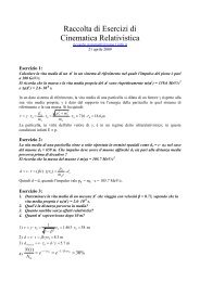
<strong>AMS</strong>-<strong>02</strong><br />
<strong>TRD</strong><br />
<strong>Gas</strong> <strong>Slow</strong> <strong>Control</strong> <strong>System</strong><br />
<strong>Specifications</strong><br />
v <strong>4.1</strong><br />
3-<strong>04</strong>-<strong>2006</strong><br />
A. Bartoloni, B. Borgia, F. Bucci, F. R. Spada<br />
INFN Sezione di Roma 1- Roma, Italy
2/45
1. ABSTRACT 5<br />
2. GAS SYSTEM FUNCTIONAL DESCRIPTION 5<br />
3. GAS CONTROL SYSTEM 8<br />
4. CONTROL SYSTEM COMPONENTS 12<br />
a. Universal <strong>Control</strong> <strong>System</strong> Module (USCM) 12<br />
b. Box-S <strong>Control</strong> Board (UGBS) 12<br />
c. Box-C <strong>Control</strong> Board (UGBC) 18<br />
d. Manifold <strong>Control</strong> Boards 22<br />
e. Manifold Local Modules (UGPS) 23<br />
f. Manifold <strong>Control</strong> Boards (UGFV) 23<br />
g. High Voltage Power Supply (UHVG) 35<br />
h. Power Distribution Box and DC-DC Converters (UGPD) 36<br />
i. Electromechanical Components. <strong>Specifications</strong> 38<br />
5. CONTROL SYSTEM TESTING AND VERIFICATION 41<br />
6. CONTROL SYSTEM OPERATIONS 41<br />
a. Ground operations 41<br />
b. Flight operations 41<br />
c. List of macro Commands 42<br />
7. GAS CONTROL SYSTEM SAFETY 43<br />
8. APPENDICES 44<br />
a. References 44<br />
b. Weight Estimate for <strong>Gas</strong> <strong>Control</strong> <strong>System</strong> 45<br />
3/45
4/45
1. Abstract<br />
The description of the <strong>TRD</strong> <strong>Gas</strong> <strong>Control</strong> <strong>System</strong> is structured as follows. The next section<br />
contains a functional description. Section 3 contains the details of the electrical controls.<br />
The components are listed in Section 4. Testing and verification are in Section 5 and<br />
Operations are in Section 6. Appendix A contains a list of contact persons for the <strong>TRD</strong> <strong>Gas</strong><br />
<strong>Slow</strong> <strong>Control</strong> <strong>System</strong>, and Appendix B contains the weight estimate for the <strong>TRD</strong> <strong>Gas</strong> <strong>Slow</strong><br />
<strong>Control</strong> <strong>System</strong><br />
2. <strong>Gas</strong> <strong>System</strong> Functional Description<br />
The <strong>TRD</strong> <strong>Gas</strong> <strong>System</strong> performs the following functions:<br />
Stores sufficient gas for the 3-5 year <strong>AMS</strong>-<strong>02</strong> mission with a safety margin of four.<br />
Transfers new gas to the <strong>TRD</strong> each day.<br />
Circulates the gas and monitors the gas content continuously.<br />
.<br />
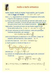
Fig. 1 <strong>TRD</strong> <strong>Gas</strong> <strong>System</strong> general layout.<br />
The 41 <strong>TRD</strong> segments are connected through manifolds to Box-C containing controls,<br />
monitors, and circulation pumps. Box-S provides Box-C with pre-mixed gas from gas<br />
supplies in a limited transfer volume (approx. 1 liter). Computer activates a feed control<br />
between Boxes S and C approximately once a day. The general layout is shown in Fig. 1.<br />
The 41 sealed <strong>TRD</strong> segments of approx. 430 cu. in. each are held at 17.4 psi. Box-C has<br />
an estimated volume of less than 150 cu. in., held below 25 psia by relief valves.<br />
5/45
Fig. 2 <strong>Gas</strong> <strong>System</strong>
Fig. 2 shows the schematic for Box-S and Box-C. Two storage vessels store the Xenon<br />
and Carbon Dioxide separately. Two mixing circuits convey the gases to the mixing<br />
vessel where the 4:1 mixture is made. A system of valves then allows the transfer of<br />
the gas from the mixing vessel to Box-C. At all points, the valves have a two-fold<br />
redundancy. Leak-before-burst vessels ensure safety in the event of high temperatures<br />
causing overpressure in the vessels during a time when gas cannot be vented, such as<br />
when the system has no electrical power. <strong>Gas</strong> from Box-S passes through the transfer<br />
valves V4a-b and V6a-b. Two pumps circulate the gas through the <strong>TRD</strong> volume in<br />
order to keep the gas mixed, allow the CO 2 sensor and gain monitor tubes to assess<br />
the properties of the gas. The pumps and CO 2 sensor are mounted inside a gas tight<br />
vessel; in the event of a pump or valve failure, pressure integrity of the system will not<br />
be lost.<br />
Fig. 2 shows one manifold segment. Each manifold segment has two valves and one<br />
pressure sensor at each end. The valves allow the isolation of the corresponding <strong>TRD</strong><br />
segment in case a leak occurs and the pressure sensors allow detection of leaks. All valves<br />
are computer controlled; if there is a large leak in any segment, that segment is closed by<br />
the control computer.
3. <strong>Gas</strong> <strong>Control</strong> <strong>System</strong><br />
The <strong>TRD</strong> <strong>Gas</strong> <strong>System</strong> is controlled via the <strong>TRD</strong> <strong>Gas</strong> <strong>System</strong> Electronics crate (UG). The<br />
crate layout is given in Fig. 3. The double redundant UGBS cards control Box-S, Box-C by<br />
the double redundant UGBC cards and the manifolds by the double redundant UGFV<br />
cards.<br />
This <strong>System</strong> includes the Monitoring and <strong>Control</strong> Computer (JMDC) and the Power<br />
Distribution Box (PDB), which provides 28 VDC power from the 120 VDC, supplied from<br />
the Space Station. Fig. 4 shows the architecture of the <strong>TRD</strong> <strong>Gas</strong> <strong>Control</strong> <strong>System</strong>.<br />
Fig. 3 <strong>Gas</strong> <strong>System</strong> Electronics Crate layout (UG crate).<br />
8/45
Fig. 4 <strong>TRD</strong> gas system command and control architecture (see text). The black lines<br />
indicate the control and monitor signal, the red ones the power supply.<br />
9/45
As outlined above, the <strong>Gas</strong> <strong>Slow</strong> <strong>Control</strong> <strong>System</strong> is composed by the following elements:<br />
UG Crate, Crate Back-Plane (UGBP) and the following modules: USCM, UGBS, UGBC,<br />
UHVG, UGFV, UGPS modules. Redundancy is implemented by duplicating all boards except<br />
UGPS modules since the manifolds themselves are redundant.<br />
Each board type will be described in § 4. A short description is given below.<br />
USCM 1 (Universal <strong>Slow</strong> <strong>Control</strong> Module) The USCM is connected to the Monitor and<br />
<strong>Control</strong> Computer and main data acquisition via CAN-BUS and to the gas system control<br />
electronics via a dedicated custom bus (USCM I/O and CTRL in Fig.4). The USCM provides<br />
output ports to command external devices and input ports to acquire control data.<br />
The circuit boards UGBS, UGBC, UHVG, UGFV and UGPS provide an electronic interface<br />
between USCM and electromechanical gas system devices. Their functions are:<br />
UGBS 2 (<strong>TRD</strong> <strong>Gas</strong> <strong>Control</strong> Board for Box-S): located in the UG Crate (<strong>TRD</strong> <strong>Gas</strong> Crate)<br />
near the Box-S, it will control its operations i.e. providing the correct gas mixture to refill<br />
the <strong>TRD</strong>, monitor the pressure and filling status. One hot and one cold UGBS board and<br />
cables are used to implement system redundancy.<br />
UGBC (<strong>TRD</strong> <strong>Gas</strong> <strong>Control</strong> Board for Box-C): located in the UG Crate near the Box-C, it<br />
will control its operations, i.e. running the pumps, opening valves to refill the <strong>TRD</strong> and<br />
monitor gas pressure. In case of overpressure, a relief valve will be opened. One hot and<br />
one cold UGBC board are used to implement system redundancy.<br />
Two sets of boards control and monitor the isolation valves and the pressure sensors of<br />
<strong>TRD</strong> manifolds; they are the UGFV and UGPS boards.<br />
UGFV controls the activation of the manifold flipper valves (164 in total) and multiplexes<br />
the 82 manifold pressure sensor signals coming from the UGPS modules (located closer to<br />
the manifold, see after) to the USCM ADC. Each board will control 41 valves pairs (for<br />
each segment valves A and C, or B and D are activated or deactivated with the same<br />
command) so that four identical boards (2 hot and 2 cold) are used (UGFV-AC, UGFV-BD).<br />
UGPS: this board sits close to the detector near the sensors and contains the circuits to<br />
adapt the pressure sensors output signals to the USCM inputs. This electronics has to<br />
operate in an external magnetic field B ≅ 200 Gauss directed along the axis of the<br />
manifold.<br />
UHVG: The UHVG board generates the high voltage power supply necessary for the BOX-<br />
C monitor tubes.<br />
UG Crate (<strong>TRD</strong> <strong>Gas</strong> <strong>Control</strong> Crate): This crate locates all the electronic boards<br />
previously described with exception of UGPS modules. This crate allocates also a <strong>TRD</strong> <strong>Gas</strong><br />
<strong>Control</strong> Backplane board (UGBP) to distribute the power supplies and USCM custom bus<br />
signals to all UG boards. Most of the <strong>TRD</strong> electronics is hosted in a single crate capable to<br />
host 12 boards, 6U-height. The standard <strong>AMS</strong> crate will be used. 3 The standard crate has<br />
a board-to-board pitch of 20.32 mm. The standard board will have two 3×32 VME<br />
connectors (0.1” pitch). The allowable height for components on component side is 11.4<br />
1 USCM Universal <strong>Slow</strong> <strong>Control</strong> Module for <strong>AMS</strong> <strong>02</strong>; III Physikalisches Institut RWTH Aachen<br />
2 In this case and in all acronyms starting with UG, U stands for Ubergangstrahlung<br />
3 For more details: http://ams.cern.ch/<strong>AMS</strong>/Electronics/mech<br />
10/45
mm and on solder side is 5 mm. It has a board thickness of 1.6 mm and a front panel<br />
width of 20 mm, with a clearance of two times 1 mm on each side.<br />
UGPD Box (<strong>Gas</strong> Power Distribution Box): This box allocates all filters, control<br />
electronics and DC-DC converters. It provides voltage and current to operate valves,<br />
pumps, other components of the <strong>TRD</strong> gas system and the command electronics. Power is<br />
derived from the Power Distribution Box (PDB) @28V, supplied from the Space Station.<br />
Converters are needed for 120, 30, 12, 5.0, 3.3 VDC.<br />
All control and monitor electronics (except UGPS modules, already specified) operate in an<br />
external magnetic field B approximately of 160 to 200 Gauss.<br />
All boards previously described will be designed using redundancy criteria to cope with<br />
failure of one element at the time. No provision is made for two or more failures on the<br />
same board. To implement this feature, for every board in operation, hot board, a standby<br />
unit, cold board, will be provided. The UGPS modules, sitting on the manifolds, will not<br />
have a cold unit, since doubling pressure sensors and valves in the manifold already<br />
provides redundancy.<br />
Hot and cold boards can be controlled by either USCM.<br />
11/45
4. <strong>Control</strong> <strong>System</strong> Components<br />
a. Universal <strong>Slow</strong> <strong>Control</strong> Module (USCM)<br />
The USCM contains the interface to the JMDC, which tests the status information of the<br />
gas system against pre-conditions and executes commands. The conditions and<br />
commands are stored in form of decision tables.<br />
Its duties are:<br />
o execute the software of the control system;<br />
o control and command the sensor, valves, and pump interface;<br />
o integrate through a serial bus (CAN-BUS) the <strong>TRD</strong> gas system in the <strong>AMS</strong> general<br />
command and control system.<br />
Two replica of the USCM, the hot and the cold (dashed box in figure refers to cold<br />
boards), are used for redundancy. These two boards control all the other boards presents<br />
in the crate. The USCM bus signals will be distributed through the backplane to all the<br />
other boards in the crate so that they could be accessed through a memory mapped I/O<br />
mechanism. All the boards will be based on the same Bus I/O interface (Le Croy protocol)<br />
implemented in an ACTEL A54SX32A FPGA.<br />
b. Box-S <strong>Control</strong> Board (UGBS)<br />
The main task of this board is to control the valves present in Box-S (V1a, V10a, V1b,<br />
V10b, V2a, V3a, V2b, V3b, V20a, V20b, V4a, V4b) with the following function<br />
o open the valves (normally closed otherwise) for a programmable period ranging<br />
from 50 to about 60000 ms<br />
This control is handled from a dedicated ACTEL A54SX32A FPGA interfacing the USCM I/O.<br />
The FPGA pilots also the two switches used to control each valve (24 in total). For each<br />
valve one switch (SW-1) is used to connect the valve to the 30 VDC power supply line,<br />
while the other switch (SW-2) it is used to open the valve for the programmed time, if<br />
connected to the 30 VDC (see Fig. 5).<br />
A voltage comparator (LM239) checks if the second switch (SW-2) is closed during the<br />
open command. The status of the SW-2 switch is accessible in two different ways by<br />
USCM:<br />
1. current status register allows the USCM to have information of the status of all<br />
SW-2 switches at the reading phase.<br />
2. event register will report, for all switches, if a close event occurred in the past.<br />
To this end, the switch transitions to the close state are stored into a 12 bits<br />
register.<br />
The register reading operation by the USCM resets it to zero. Comparing these two<br />
registers, a monitor of command flow and of the working condition is possible.<br />
12/45
The ADCs necessary to convert the output signals from 4 GP50 pressure sensors (P1a,<br />
P2a, P1b, P2b) and from 3 KULITE pressure sensors (PK1c, PK1d, PK2c) are also present<br />
on the board.<br />
Fig. 5: Marotta Valve Circuit<br />
The USCM does not give direct commands to the valves. The USCM will operate on valves,<br />
and on all the other devices, through I/O operations, using the Lecroy bus, at the UGBS<br />
addresses, according to the following commands table.<br />
When opening valves, software program should take care of switching off heaters.<br />
13/45
Table 1 – Box-S Commands<br />
Command Function Comment<br />
MVENW<br />
Enable Valves<br />
(close SW-1)<br />
12 bits specify valves to be<br />
enabled (connected to 30 VDC)<br />
MVENR<br />
Enable valve status<br />
(SW-1 status)<br />
Use 12 bits to return which of<br />
the 12 valves is enabled<br />
OPEN_V1a Open valve V1a 16 bits set the open period<br />
(SW-2 is closed for the<br />
specified period) (ms)<br />
OPEN_V2a Open valve V2a “<br />
OPEN_V3a Open valve V3a “<br />
OPEN_V4a Open valve V4a “<br />
OPEN_V10a Open valve V10a “<br />
OPEN_V20a Open valve V20a “<br />
OPEN_V1b Open valve V1b “<br />
OPEN_V2b Open valve V2b “<br />
OPEN_V3b Open valve V3b “<br />
OPEN_V4b Open valve V4b “<br />
OPEN_V10b Open valve V10b “<br />
OPEN_V20b Open valve V20b “<br />
OPEN_V20a&V20b Open both valves V20a<br />
“<br />
OPEN_SPARE<br />
SW2CURRD<br />
and V20b<br />
Read the actual status of<br />
the SW-2<br />
SW2EVERD Read the event register<br />
for the SW2 switches<br />
VRENWR Enable Board Voltage<br />
Regulators<br />
14 bit are used to report info<br />
for all SW-2 switches in a single<br />
reading<br />
"<br />
2 bits are used to switch on/off<br />
the 5V and 30V voltage<br />
regulators<br />
2 bits are used to report info<br />
about 5V and 30V regulators<br />
VRENRD<br />
Read Voltage Regulators<br />
Status<br />
READ_P1a Read P1a The 12 output bits of the ADC<br />
are returned to the USCM<br />
READ_P2a Read P2a "<br />
READ_P1b Read P1b "<br />
READ_PK1c Read PK1c "<br />
READ_PK1d Read PK1d "<br />
READ_PK2c Read PK2c "<br />
14/45
Four cables (JS1A, JS1B, JS2, JS3) connect the UGBS boards to the Box-S and micro-D<br />
socket connectors are used for connection on both sides; the pin-out of such connectors is<br />
stated in the following tables.<br />
Table 2 – JS1 Pin Assignment<br />
JS1A and JS1B (37 pin)<br />
Pin # Connection<br />
1 unconnected<br />
2 V1a +Excitation Voltage<br />
3 V10a +E.V.<br />
4 V3a +E.V.<br />
5 V20b +E.V.<br />
6 V3b +E.V.<br />
7 V4a +E.V.<br />
8 VSpare1 +E.V.<br />
9 Unconnected<br />
10 Unconnected<br />
11 V1a –E.V.<br />
12 V10a –E.V.<br />
13 V3a –E.V.<br />
14 V20b –E.V.<br />
15 V3b –E.V.<br />
16 V4a –E.V.<br />
17 VSpare1 –E.V.<br />
18 Unconnected<br />
19 Unconnected<br />
20 V20a +E.V.<br />
21 V2a +E.V.<br />
22 V1b +E.V.<br />
23 V10b +E.V.<br />
24 V2b +E.V.<br />
25 V4b +E.V.<br />
26 VSpare2 +E.V.<br />
27 Unconnected<br />
28 Unconnected<br />
29 V20a -E.V.<br />
30 V2a -E.V.<br />
31 V1b -E.V.<br />
32 V10b -E.V.<br />
33 V2b -E.V.<br />
34 V4b -E.V.<br />
35 VSpare2 –E.V.<br />
36 Unconnected<br />
37 Unconnected<br />
15/45
Table 3 – JS2 Pin Assignment<br />
JS2 (21 pin)<br />
Pin # Connection<br />
1 Unconnected<br />
2 H1 +E.V.<br />
3 H2 +E.V.<br />
4 H3 +E.V.<br />
5 HSpare1 +E.V.<br />
6 HSpare2 +E.V.<br />
7 Unconnected<br />
8 Dallas1 VCC<br />
9 Dallas1 GND<br />
10 Dallas1 IO<br />
11 Unconnected<br />
12 H1 –E.V.<br />
13 H2 –E.V.<br />
14 H3 –E.V.<br />
15 HSpare1 –E.V.<br />
16 HSpare2 –E.V.<br />
17 Unconnected<br />
18 Dallas2 VCC<br />
19 Dallas2 GND<br />
20 Dallas2 IO<br />
21 Unconnected<br />
16/45
Table 4 – JS3 Pin Assignment<br />
JS3 (31 pin)<br />
Pin # Connection<br />
1 Unconnected<br />
2 P1a +Excitation Voltage (+10V)<br />
3 P2a +E.V. (+10V)<br />
4 P1b +E.V. (+10V)<br />
5 P2b +E.V. (+10V)<br />
6 PK1c +E.V. (+30V)<br />
7 PK2c +E.V. (+30V)<br />
8 PK1d +E.V. (+30V)<br />
9 P1a +Output<br />
10 P2a +Output<br />
11 P1b +Output<br />
12 P2b +Output<br />
13 PK1c +Output<br />
14 PK2c +Output<br />
15 PK1d +Output<br />
16 Unconnected<br />
17 P1a –E.V. (GND)<br />
18 P2a –E.V. (GND)<br />
19 P1b –E.V. (GND)<br />
20 P2b –E.V. (GND)<br />
21 PK1c –E.V.(GND)<br />
22 PK2c –E.V. (GND)<br />
23 PK1d –E.V. (GND)<br />
24 P1a –Output (GND)<br />
25 P2a –Output (GND)<br />
26 P1b –Output (GND)<br />
27 P2b –Output (GND)<br />
28 PK1c –Output<br />
29 PK2c -Output<br />
30 PK1d -Output<br />
31 Unconnected<br />
17/45
c. Box-C <strong>Control</strong> Board (UGBC)<br />
In the following, we summarize the devices controlled by the UGBC board with the relative<br />
control functions:<br />
- n.4 Marotta MV100 solenoid valves (V6a, V6b, V18a, V18b)<br />
<br />
<br />
<br />
open the valves (normally closed otherwise) for a programmable period<br />
ranging from 10 to about 60000 ms<br />
test the mechanical status of the valves<br />
test the energizing status of the valves<br />
- n.2 Burkert 6613 flipper valves (V8a, V8b)<br />
<br />
<br />
open the valves<br />
close the valves<br />
- n.2 KNM pumps (CP1, CP2)<br />
<br />
<br />
turn on/off the pumps<br />
change pump speed<br />
- n.3 GP50-7900 pressure sensors (P3, P4)<br />
- n.4 monitor straw tubes<br />
signal shaping and multiplexing towards the MCA.<br />
n.1 MCA interface through RS232 connection.<br />
n.1 CO 2 analyser through RS232 connection.<br />
This control is handled from a dedicated ACTEL A54SX32A FPGA interfacing the USCM I/O.<br />
The FPGA acts on the MV100 valves and on pumps using the same control scheme<br />
described in the previous paragraph. Two different power voltages (24 and 12 Volts)<br />
change pumps speed.<br />
No direct command from USCM is given to valves. The USCM operates on valves through<br />
I/O write and read operations at the UGBC addresses, according to the following tables.<br />
18/45
Table 5 – Box-C Commands<br />
Command Function Comment<br />
MVENW<br />
Enable Valves<br />
(close SW-1)<br />
4 bits specify valves to be enabled<br />
(connected to the 30 VDC)<br />
MVENR<br />
Enable valves status<br />
(SW-1 status)<br />
Use 4 bits to return which of the 4<br />
Marotta valves is enabled<br />
OPEN_V6a Open valve V6a 16 bits set the open time<br />
(SW-2 is closed for the specified<br />
time)<br />
OPEN_V18a Open valve V18a “<br />
OPEN_V6b Open valve V6b “<br />
OPEN_V18b Open valve V18b “<br />
OPEN_V6a&V18a Open both V6a and<br />
"<br />
V18a valves<br />
OPEN_V6b&V18b Open both V6b and<br />
"<br />
V18b valves<br />
CURS<strong>TRD</strong> Read the actual 12 bits used to report all information<br />
status of the Marotta<br />
valve<br />
EVENTS<strong>TRD</strong> Read the past status<br />
"<br />
of the Marotta valve<br />
OPCL_V8a Open or close V8a 3 bits specify<br />
if the valve should be open or<br />
closed<br />
OPCL_V8b Open or close V8b “<br />
PENWR<br />
Set the pumps status 4 bits specify pump enable<br />
(connection to power supply) and<br />
pump speed (24V or 12V)<br />
PENRD Read pump status “<br />
RUN/STOP_CP1 Start or stop CP1 1 bit specifies if pump should be<br />
turn on or off<br />
RUN/STOP_CP2 Start or Stop CP2 "<br />
MCASELW<br />
MCASELRD<br />
VRENWR<br />
VRENRD<br />
RS232WR<br />
Select the monitor<br />
tube to be connect<br />
to the MCA<br />
Reports the monitor<br />
tube connected to<br />
the MCA<br />
Enable Board Voltage<br />
Regulators<br />
Read Voltage<br />
Regulators Status<br />
Set the status of the<br />
serial port<br />
4 monitor tubes are present in BOX-<br />
C and one at the time could be<br />
connected to the MCA<br />
"<br />
3 bits are used to switch on/off the<br />
5V, 12V and 24V voltage regulators<br />
3 bits are used to report info about<br />
5V, 12V and 24V voltage regulators<br />
One serial port is used to connect<br />
the USCM to the MCA or to the CO 2<br />
19/45
analyzer<br />
RS232RD<br />
Report the status of<br />
"<br />
the serial port<br />
READ_P3 Read P3 The 12 output bits of the ADC are<br />
returned to the USCM<br />
READ_P4 Read P4 "<br />
Three cables (JC1, JC2, JC3) connect the UGBC boards to the Box-C and micro-D socket<br />
connectors are used for connection on both sides; the pin-out of such connectors are<br />
defined in the following tables.<br />
Table 6 – JC1 Pin Assignment<br />
(Power)<br />
JC1 (21 pin)<br />
Pin # Connection<br />
1 unconnected<br />
2 CP1 –E.V.<br />
3 CP1 +Excitation Voltage<br />
4 P3 & P4 -E.V. (GND)<br />
5 unconnected<br />
6 V8a +E.V.<br />
7 V8b +E.V.<br />
8 CO 2 +E.V. (8.5V)<br />
9 MCA –E.V. (GND)<br />
10 Tube amps –E.V. (GND)<br />
11 unconnected<br />
12 CP2 +E.V.<br />
13 CP2 –E.V.<br />
14 P3 & P4 +E.V. (12 V)<br />
15 unconnected<br />
16 unconnected<br />
17 V8a –E.V.<br />
18 V8b –E.V.<br />
19 CO 2 –E.V. (GND)<br />
20 Tube amps +E.V. (5 V)<br />
21 MCA +E.V. (12 V)<br />
20/45
Table 7 – JC2 Pin Assignment<br />
(Marotta valves)<br />
JC2 (9 pin)<br />
Pin # Connection<br />
1 V6a +Excitation Voltage<br />
2 V6a –E.V.<br />
3 V6b +E.V.<br />
4 V6b –E.V.<br />
5 V18a +E.V.<br />
6 V18a –E.V.<br />
7 V18b +E.V.<br />
8 V18b –E.V.<br />
9 Unconnected<br />
Table 8 – JC3 Pin Assignment<br />
(Signals)<br />
JC3 (25 pin)<br />
Pin # Connection<br />
1 Unconnected<br />
2 CO 2 _RX.<br />
3 Unconnected<br />
4 Unconnected<br />
5 Unconnected<br />
6 Amp. Enable 2<br />
7 Amp Enable 4<br />
8 Unconnected<br />
9 P3 +Output<br />
10 P3 –Output (GND)<br />
11 Unconnected<br />
12 Unconnected<br />
13 Unconnected<br />
14 Unconnected<br />
15 MCA_TX<br />
16 MCA_RX<br />
17 Unconnected<br />
18 Amp Enable 1<br />
19 Amp Enable 3<br />
20 Unconnected<br />
21 Unconnected<br />
22 Unconnected<br />
23 P4 +Output<br />
24 P4 –Output (GND)<br />
25 CO 2 _TX<br />
21/45
d. Manifold <strong>Control</strong> Boards<br />
This electronics, as mentioned in the introduction, controls the flipper valves (FV in the<br />
following) and conditions the pressure sensors output signal (PS in the following) of<br />
manifold <strong>TRD</strong> electronics.<br />
From a mechanical point of view, manifold devices are arranged in 8 Input modules and 8<br />
Output modules. With reference to Fig. 2, each Input module contains the FVA, FVC and<br />
PSA for 5 or 6 segments while each Output module contains FVC, FVD and PSB for 5 or 6<br />
segments. In addition, the electronics will use such modularity.<br />
PS output signals are handled in two sections: the UGPS modules and UGFV boards.<br />
UGPS modules are designed to adapt the signals to USCM ADC input while the UGFV<br />
boards are used to multiplex them to the USCM ADC input lines. FV control commands<br />
(Close and Open) coming from the USCM are decoded in the UGFV boards The UGFV<br />
generates the necessary valve control signals.<br />
In the following paragraph, we discuss the pressure sensor readout (UGPS modules and<br />
UGFV board) and then the flipper valve control board (UGFV board).<br />
Fig. 6: 26PC-C pressure sensor output signal conditioning.<br />
22/45
e. Manifold Local Modules (UGPS):<br />
In this paragraph, we describe the first part of readout electronics for the pressure<br />
sensors. The duty of this module is to transform the bipolar signal coming out from<br />
pressure sensors to a unipolar signal suitable as USCM ADC input (signal conditioning).<br />
This electronics sits as close as possible to pressure sensors and will use the same<br />
modularity used in the mechanical assembly of the sensors.<br />
Presently five Pressure Sensors (PS) and 10 Flipper Valves (FV) are mechanically<br />
assembled together in 14 manifold modules. Two additional modules assembe 6 PS and<br />
12 FV.<br />
Each UGPS module will provide signals conditioning for the pressure sensors that are<br />
assembled together. In such way the readout electronics of pressure sensors belonging to<br />
different segments, (i.e. P5A, P7A, P8A, P38A, P40A for module 1) are grouped in the<br />
same UGPS module, with the same modularity of sensors. The 82 sensors are grouped in<br />
16 modules, namely 2 boards with 6 pressure sensors and 14 with only 5.<br />
The pressure sensor (Honeywell 26PC-C) measures the difference of the pressure between<br />
the two sides of the sensor as DC voltage difference around -100 mV to +100 mV before<br />
conditioning, 0-4 V after conditioning. The typical range, the voltage corresponding to the<br />
maximum differential pressure measured, is 100mV (97 Min, 103 Max) for a pressure of<br />
15 psi. The sensor signals are transformed to a single ended signal in the range 0 to 4.096<br />
V VDC, resolution ±1 mV, suitable as USCM ADC line input. Then the 82 signals are<br />
multiplexed in the ADC input (6 of the 32 lines are used). This schematic is represented in<br />
Fig. 6. The output signals of pressure sensors, indicated as Out + and Out – in Fig. 6, are<br />
amplified and transformed in a single ended signal in the UGPS module and then are<br />
multiplexed to six different USCM ADC lines.<br />
The UGPS module is connected through a single cable (JMx-xx) to the corresponding<br />
UGFV board and such cable is used also to connect the flipper valve located on the<br />
associated module (see next paragraph).<br />
f. Manifold <strong>Control</strong> Boards (UGFV)<br />
There are four UGFV boards located in the UG-Crate, all implementing the same functions.<br />
Two (one hot and one cold) named UGFV-AC are used to pilot all the “A” and “C” FV and<br />
to interface all the PS located in the 8 Input manifold modules (PAx). The other two (one<br />
hot and one cold) named UGFV-BD are used to pilot all “B” and “D” flipper valve and to<br />
interface all the PS located in the Output manifold modules (PBx) (see fig 2).<br />
One of the functions of the UGFV board is to multiplex the 41 conditioned PS signals,<br />
coming from the 8 UGPS modules associated to the UGFV board, to 6 ADC input port of<br />
USCM (see Fig. 6). It is possible to read simultaneously all the 26PC-C pressure sensors<br />
located on the same manifold module using this scheme.<br />
A dedicated UGFV board command allows the USCM to select the desired module (see<br />
command list, Table 13).<br />
Through the backplane board, each UGFV board is connected to six different USCM ADC<br />
input line and in particular :<br />
UGFV-AC (hot) will use ADC input line 0 to 5<br />
23/45
UGFV-AC (cold) will use ADC input lines 8 to 13<br />
UGFV-BD (hot) will use ADC input lines 16 to 21<br />
UGFV-BD (cold) will use ADC input lines 24 to 29<br />
The following tables state the correspondence between modules, PS (plus relative <strong>TRD</strong><br />
segments) and USCM ADC Input lines<br />
Table 9 – Correspondence PS-ADC Inputs<br />
UGFV-AC hot (UGFV-AC cold)<br />
MODULE<br />
ADC-0<br />
(8)<br />
ADC-1<br />
(9)<br />
ADC-2<br />
(10)<br />
ADC-3<br />
(11)<br />
ADC-4<br />
(12)<br />
ADC-5<br />
(13)<br />
1 PS-5A PS-7A PS-8A PS-38A PS-40A N.U.<br />
2 PS-10A PS-16A PS-18A PS-25A PS-25A N.U.<br />
3 PS-12A PS-14A PS-20A PS-22A PS-29A N.U.<br />
4 PS-6A PS-31A PS-37A PS-39A PS-41A N.U.<br />
5 PS-1A PS-3A PS-9A PS-24A PS-34A PS-36A<br />
6 PS-11A PS-17A PS-19A PS-26A PS-28A N.U.<br />
7 PS-13A PS-15A PS-21A PS-23A PS-30A N.U.<br />
8 PS-2A PS-4A PS-32A PS-33A PS-35A N.U.<br />
UGFV-BD hot (UGFV-BD cold)<br />
MODULE<br />
ADC16<br />
(24)<br />
ADC17<br />
(25)<br />
ADC18<br />
(26)<br />
ADC19<br />
(27)<br />
ADC20<br />
(28)<br />
ADC21<br />
(29)<br />
1 PS-5B PS-7B PS-8B PS-38B PS-40B N.U.<br />
2 PS-10B PS-16B PS-18B PS-25B PS-25B N.U.<br />
3 PS-12B PS-14B PS-20B PS-22B PS-29B N.U.<br />
4 PS-6B PS-31B PS-37B PS-39B PS-41B N.U.<br />
5 PS-1B PS-3B PS-9B PS-24B PS-34B PS-36B<br />
6 PS-11B PS-17B PS-19B PS-26B PS-28B N.U.<br />
7 PS-13B PS-15B PS-21B PS-23B PS-30B N.U.<br />
8 PS-2B PS-4B PS-32B PS-33B PS-35B N.U.<br />
The other function of this board is the main control of flipper valve status. An ACTEL<br />
A54SX32A FPGA is used to interface the USCM I/O bus and to drive the switches used to<br />
control each flipper valve.<br />
24/45
UGFV boards will be used to open or close each segment independently and in particular<br />
UGFV-AC boards will act simultaneously on FVA and FVC while UGFV-BD boards on FVB<br />
and FVD.<br />
USCM will open or close the valve through an appropriate command as specified in the<br />
following UGFV command table.<br />
Table 10 – Manifold Commands<br />
Command Name Function Comment<br />
OP/CL_MOD1<br />
OP/CL_MOD2<br />
OP/CL_MOD2<br />
OP/CL_MOD4<br />
OP/CL_MOD5<br />
OP/CL_MOD6<br />
OP/CL_MOD7<br />
OP/CL_MOD8<br />
VRENWR<br />
VRENRD<br />
PSMUXWR<br />
PSMUXRD<br />
Open or close valves<br />
on module 1<br />
Open or close valves<br />
on module 2<br />
Open or close valves<br />
on module 3<br />
Open or close valves<br />
on module 4<br />
Open or close valves<br />
on module 5<br />
Open or close valves<br />
on module 6<br />
Open or close valves<br />
on module 7<br />
Open or close valves<br />
on module 8<br />
Enable Board Voltage<br />
Regulators<br />
Read Voltage<br />
Regulators Status<br />
Select the module to<br />
connect to the USCM<br />
ADC inputs<br />
Report number of<br />
modules connected to<br />
the USCM ADC inputs<br />
6+3 bits specify valves (segments)<br />
to be opened or closed<br />
"<br />
"<br />
"<br />
"<br />
"<br />
"<br />
"<br />
2 bits are used to switch on/off the<br />
5V, and 12V voltage regulators<br />
2 bits are used to report info about<br />
5V and 12V voltage regulators<br />
15 bits allows to specify which<br />
module should be connected<br />
"<br />
The manifolds are controlled through the UGVF cards. One USCM scans the readings of<br />
the pressure sensors in the manifolds. The readings are reported to the main <strong>AMS</strong>-<strong>02</strong> data<br />
computer (JMDC). If the JMDC detects a leak, it will close the corresponding manifold<br />
valves to isolate the leaky segment. This operation can also be performed from ground.<br />
Eight cables (JM1 to JM8) connect the UGFV boards to the corresponding 8 manifold<br />
modules and for connection on both sides micro-D socket connectors are used. The pinout<br />
of such connectors are defined in the following tables.<br />
25/45
Table 11 – JM1 Pin Assignment<br />
JM1 (21 pin)<br />
Pin # Connection<br />
1 PS5 Single Ended Output<br />
2 PS7 S.E.O.<br />
3 PS8 S.E.O.<br />
4 PS38 S.E.O.<br />
5 PS40 S.E.O.<br />
6 Unconnected<br />
7 PS +Excitation Voltage (12V)<br />
8 FV5 +E.V.<br />
9 FV7 +E.V:<br />
10 FV8 +E.V.<br />
11 FV38 +E.V:<br />
12 FV40 +E.V.<br />
13 Unconnected<br />
14 FV5 -E.V.<br />
15 FV7 -E.V:<br />
16 FV8 -E.V.<br />
17 FV38 -E.V:<br />
18 FV40 -E.V.<br />
19 Unconnected<br />
20 PS -E.V. (GND)<br />
21 PS -E.V. (GND)<br />
26/45
Table 12 – JM2 Pin Assignment<br />
JM2 (21 pin)<br />
Pin # Connection<br />
1 PS10 Single Ended Output<br />
2 PS16 S.E.O.<br />
3 PS18 S.E.O.<br />
4 PS25 S.E.O.<br />
5 PS27 S.E.O.<br />
6 Unconnected<br />
7 PS +Excitation Voltage (12V)<br />
8 FV10 +E.V.<br />
9 FV16 +E.V:<br />
10 FV18 +E.V.<br />
11 FV25 +E.V:<br />
12 FV27 +E.V.<br />
13 Unconnected<br />
14 FV10 -E.V.<br />
15 FV16 -E.V:<br />
16 FV18 -E.V.<br />
17 FV25 -E.V:<br />
18 FV27 -E.V.<br />
19 Unconnected<br />
20 PS -E.V. (GND)<br />
21 PS -E.V. (GND)<br />
27/45
Table 13 – JM3 Pin Assignment<br />
JM3 (21 pin)<br />
Pin # Connection<br />
1 PS12 Single Ended Output<br />
2 PS14 S.E.O.<br />
3 PS20 S.E.O.<br />
4 PS22 S.E.O.<br />
5 PS29 S.E.O.<br />
6 Unconnected<br />
7 PS +Excitation Voltage (12V)<br />
8 FV12 +E.V.<br />
9 FV14 +E.V:<br />
10 FV20 +E.V.<br />
11 FV22 +E.V:<br />
12 FV29 +E.V.<br />
13 Unconnected<br />
14 FV12 -E.V.<br />
15 FV14 -E.V:<br />
16 FV20 -E.V.<br />
17 FV22 -E.V:<br />
18 FV29 -E.V.<br />
19 Unconnected<br />
20 PS –E.V. (GND)<br />
21 PS –E.V. (GND)<br />
28/45
Table 14 – JM4 Pin Assignment<br />
JM4 (21 pin)<br />
Pin # Connection<br />
1 PS6 Single Ended Output<br />
2 PS31 S.E.O.<br />
3 PS37 S.E.O.<br />
4 PS39 S.E.O.<br />
5 PS41 S.E.O.<br />
6 Unconnected<br />
7 PS +Excitation Voltage (12V)<br />
8 FV6 +E.V.<br />
9 FV31 +E.V:<br />
10 FV37 +E.V.<br />
11 FV39 +E.V:<br />
12 FV41 +E.V.<br />
13 Unconnected<br />
14 FV6 -E.V.<br />
15 FV31 -E.V:<br />
16 FV37 -E.V.<br />
17 FV39 -E.V:<br />
18 FV41 -E.V.<br />
19 Unconnected<br />
20 PS –E.V. (GND)<br />
21 PS –E.V. (GND)<br />
29/45
Table 15 – JM5 Pin Assignment<br />
JM5 (21 pin)<br />
Pin # Connection<br />
1 PS1 Single Ended Output<br />
2 PS3 S.E.O.<br />
3 PS9 S.E.O.<br />
4 PS24 S.E.O.<br />
5 PS34 S.E.O.<br />
6 PS36 S.E.O.<br />
7 PS +Excitation Voltage (12V)<br />
8 FV1 +E.V.<br />
9 FV3 +E.V:<br />
10 FV9 +E.V.<br />
11 FV24 +E.V:<br />
12 FV34 +E.V.<br />
13 FV36 +E.V.<br />
14 FV1-E.V.<br />
15 FV3 -E.V:<br />
16 FV9 -E.V.<br />
17 FV24 -E.V:<br />
18 FV34 –E.V.<br />
19 FV36 -E.V.<br />
20 PS –E.V. (GND)<br />
21 PS –E.V. (GND)<br />
30/45
Table 16 – JM6 Pin Assignment<br />
JM6(21 pin)<br />
Pin # Connection<br />
1 PS11ingle Ended Output<br />
2 PS17.E.O.<br />
3 PS19.E.O.<br />
4 PS26.E.O.<br />
5 PS28.E.O.<br />
6 Unconnected<br />
7 PS +Excitation Voltage (12V)<br />
8 FV11 +E.V.<br />
9 FV17 +E.V:<br />
10 FV19 +E.V.<br />
11 FV26 +E.V:<br />
12 FV28 +E.V.<br />
13 Unconnected<br />
14 FV11 -E.V.<br />
15 FV17 -E.V:<br />
16 FV19 -E.V.<br />
17 FV26 -E.V:<br />
18 FV28 -E.V.<br />
19 Unconnected<br />
20 PS –E.V. (GND)<br />
21 PS –E.V. (GND)<br />
31/45
Table 17 – JM7 Pin Assignment<br />
JM7 (21 pin)<br />
Pin # Connection<br />
1 PS13 Single Ended Output<br />
2 PS15 S.E.O.<br />
3 PS21 S.E.O.<br />
4 PS23 S.E.O.<br />
5 PS30 S.E.O.<br />
6 Unconnected<br />
7 PS +Excitation Voltage (12V)<br />
8 FV13 +E.V.<br />
9 FV15 +E.V:<br />
10 FV21 +E.V.<br />
11 FV23 +E.V:<br />
12 FV30 +E.V.<br />
13 Unconnected<br />
14 FV13 -E.V.<br />
15 FV15 -E.V:<br />
16 FV21 -E.V.<br />
17 FV23 -E.V:<br />
18 FV30 -E.V.<br />
19 Unconnected<br />
20 PS –E.V. (GND)<br />
21 PS –E.V. (GND)<br />
32/45
Table 18 – JM8 Pin Assignment<br />
JM8 (21 pin)<br />
Pin # Connection<br />
1 PS2 Single Ended Output<br />
2 PS4 S.E.O.<br />
3 PS32 S.E.O.<br />
4 PS33 S.E.O.<br />
5 PS35 S.E.O.<br />
6 Unconnected<br />
7 PS +Excitation Voltage (12V)<br />
8 FV2 +E.V.<br />
9 FV4 +E.V:<br />
10 FV32 +E.V.<br />
11 FV33 +E.V:<br />
12 FV35 +E.V.<br />
13 Unconnected<br />
14 FV2 -E.V.<br />
15 FV4 -E.V:<br />
16 FV32 -E.V.<br />
17 FV33 -E.V:<br />
18 FV35 -E.V.<br />
19 Unconnected<br />
20 PS –E.V. (GND)<br />
21 PS –E.V. (GND)<br />
33/45
The following scheme draws the cable connection between UGFV boards, one Input, and<br />
one Output manifold module.<br />
Fig. 7: Manifold electrical cabling layout.<br />
34/45
g. High Voltage board (UHVG)<br />
The UHVG board generates the high voltage that gives power to the Box-C monitor tubes.<br />
It is based on the LeCroy MHV100 High Voltage <strong>Control</strong>ler/Generator [ref. 3], a custom<br />
CMOS integrated circuit that integrates all digital communications, digital-to-analog and<br />
analog-to-digital converters, the analog feedback loop and output drivers required to<br />
implement a single high voltage converter channel.<br />
In the UHVG, 7 chips are used to implement 7 independent high voltage channels, that<br />
can be programmed and used independently.<br />
A maximum of 2000 VDC can be delivered by each channel.<br />
The main features that the board provides are the following:<br />
• set overcurrent value (common to all channels)<br />
• set overvoltage value (common to all channels)<br />
• for each channel:<br />
o set high voltage value on the corresponding chip’s DAC<br />
o enable HV output<br />
o disable HV output<br />
o read back the HV value set in the DAC<br />
If a voltage value higher than the overvoltage is sent to output, the chip will trip.<br />
The UHVG needs as power input 3.3 VDC and, in addition, 5.0 VDC and 120 VDC with a<br />
common, independent ground (AGND).<br />
Table 19- UHVG commands<br />
Command<br />
Select LeCroy chip<br />
Set HV<br />
Set OVC<br />
Set OVV<br />
ENABLE<br />
DISABLE<br />
Get HV status<br />
Get LC chip status<br />
Comment<br />
select 1 to 7 HV output<br />
set HV output value<br />
set overcurrent value<br />
set overvoltage value<br />
enable HV output<br />
disable HV output<br />
HV on/off<br />
get error status if OV or OC<br />
35/45
h. Power Distribution Box and DC-DC Converters (UGPD)<br />
The UGPD (UG crate Power Distributor) generates all the necessary power supplies for the<br />
UG crate. It receives two +28 VDC lines from the PBD (Power Distribution Box); one line<br />
used to generate the “hot” voltages required in the UG crate and the second one for the<br />
“cold” modules.<br />
Fig. 8 illustrates the block diagram of UGPD.<br />
Fig. 8: Block diagram of the power distribution box UGPD.<br />
The UGPD is made up of:<br />
1 double filter board (CAEN S9011B2)<br />
1 double control board (CAEN S9011AUG)<br />
1 double +5.6 Volts converter (CAEN S9054)<br />
1 double +3.6 Volts converter (CAEN S9053)<br />
1 double +120 Volts converter (CAEN S9056)<br />
2 +12 Volts converters (INTERPOINT SMLFHP12)<br />
2 +30 Volts converters (INTERPOINT SMLFHP15)<br />
36/45
The main functions that the controller board must perform are:<br />
- controlling the DC-DC converter status<br />
- controlling the DC-DC converters turning on/off<br />
- controlling the UGPD boards temperature<br />
The DC-DC converters chosen are compliant with the power supply requirements of the<br />
<strong>TRD</strong> <strong>Gas</strong> system stated in the following table.<br />
Table 20- Power Supply requirements<br />
Voltage/<br />
destination<br />
Nominal<br />
(W)<br />
Peak<br />
(W)<br />
Continuous<br />
(W)<br />
30 Volt<br />
3xMarotta Valves 90.00 90.00 0.00<br />
3xKulite PS 0,60 0.60 0.60<br />
2xHeater 20.00 0.00 0.00<br />
Pump (12V/24V) 0.00 2.50 2.50<br />
Electronics 1,20 1.20 1.20<br />
Total n.a. 94.30 4.30<br />
12 Volt<br />
2xFlipper Valve 3.00 3.00 0.00<br />
MCA 0.00 0.30 0.30<br />
Spirometer (8,5V) 0.00 0.85 0.85<br />
6xGP50 7.50 7.50 7.50<br />
82x26PCC 2.00 2.00 2.00<br />
Electronics 0.72 0.72 0.72<br />
Total n.a. 14.37 11.37<br />
5 Volt<br />
Electronics 5.00 5.00 5.0<br />
3,3 Volt<br />
Electronics 8.00 8.00 8.0<br />
Gran total 122.92 29.92<br />
37/45
i. Electromechanical components. <strong>Specifications</strong><br />
Table 21 – Components BOX-S<br />
# Item n. Power Output Input Timing Freq. Redun. Maker<br />
1 Valves MV197 12 30W; @30±2V switch on/off 18-30V 100±20<br />
ms<br />
5/d yes Marotta<br />
2 Pressure GP50 Sensor 7900 4 0.14W @<br />
10±1 V<br />
0-5V, ±0.1% n.a. < 4 ms continuous yes GP:50<br />
3 Pressure Sensor ETM-86-375-300A 3 @30±2V n.a. Kulite<br />
4 Temperature Sensors DS1820 4 1/30 m Dallas<br />
38/45
Table 22 – Components BOX-C<br />
# Item n. Power Output Input Timing Freq. Redun. Maker<br />
1 Valves MV100 4<br />
2 Pressure Sensor 7900 3<br />
3 Flipper valves 6123 2<br />
4 Diaphragm pump, UNMP30KNDC 2<br />
5 Spirometer 2115 1<br />
6 MCA 8000A (?) 1<br />
7 Monitor tubes (+1 µCi Fe 55 source) 4<br />
8 UGHV 1<br />
9 Preamp monitor tubes 1<br />
30W @30±2V<br />
1A<br />
0.14W<br />
@10VDC<br />
1.5 W @12V<br />
125mA<br />
2.5 W @ 24V<br />
1.25 W @12V<br />
4.8 W, @8V<br />
300 W @9V,<br />
AC adapter<br />
(115 V)<br />
1100-1400 V<br />
120V<br />
20mA @5V<br />
switch on/off 18-30V 100±10<br />
ms<br />
1/d yes Marotta<br />
0-5V, 0.1% < 4 ms continuous yes GP:50<br />
n.a.<br />
RS-232<br />
RS-232,<br />
4.8-115.6 kb/s<br />
open:<br />
+12±1V<br />
close: -<br />
12±1V<br />
0-12-<br />
24V±10%<br />
0-+5 V or<br />
0-+10 V<br />
Table 23 – Components Manifolds<br />
# Item n. Power Output Input Timing Freq. Redun. Maker<br />
1 Pressure Sensors 26PC-CCFA6D 82 25 mW @10±1<br />
V<br />
2 Flipper valves 6123 164 1.5 W@12±1V<br />
125mA<br />
0-0.1 V 1±0.1ms 1/5 min yes Honeywell<br />
5. <strong>Control</strong> <strong>System</strong> Testing and Verification<br />
Tests for qualification and acceptance should conform to the following guidelines:<br />
• For EMC qualification test, the Space Station Electromagnetic Emission and<br />
Susceptibility Requirement (SSP3<strong>02</strong>37) paragraphs RS<strong>02</strong>, RS03, RE<strong>02</strong> should be<br />
used.<br />
• For vibration qualification and acceptance test, a 3D sine-random-sine test<br />
sequence with sine 10-2000 Hz constant acceleration of 0.5 g and 90 seconds<br />
random peak vibration level of 0.4 g 2 /Hz from 80 to 500 Hz, g rms equal to 6.8 g,<br />
should be used.<br />
• For qualification thermo-vacuum test, a pressure value p
c. List of macro commands<br />
Commands to Box-S<br />
BSC1. Open Xe vessel to fill mixing vessel D<br />
BSC2. Open CO 2 vessel to fill mixing vessel D<br />
BSC3. Power on heaters<br />
BSC4. Monitor pressure in D vessel<br />
BSC5. Open valves V4/V6 to fill Box-C<br />
BSC6. Open valves V4/V18 to empty/adjust pressure in mixing vessel D<br />
BSC7. Pressure and temperature measurements<br />
BSC8. High rate scan cycle of pressure and temperature measurement<br />
BSC9. Low rate scan cycle of pressure and temperature measurement<br />
Commands to Box-C<br />
BCC1. Start gas circulation, open valve V8, power on pump CP1 or CP2<br />
BCC2. Vary pump speed<br />
BCC3. Pressure and temperature measurements<br />
BCC4. Monitor gas composition<br />
Commands to Manifold<br />
BMC1. Leak test in segment n<br />
BMC2. Close segment n<br />
BMC3. Test valves open/close<br />
BMC4. Pressure monitoring<br />
NB: each command has an alternative command for failure recovery.<br />
42/45
7. <strong>Gas</strong> <strong>Control</strong> <strong>System</strong> Safety<br />
During Flight:<br />
The gas system electronics is designed so that the gas system is automatically taken to a<br />
“Safe Mode” in case of communication failure.<br />
For Box-S this means all valves closed. The Marotta MV197 solenoid valves in Box-S are<br />
normally closed and remain in that state if there is a power loss.<br />
For Box-C to be defined<br />
For Manifolds to be defined<br />
43/45
Appendices<br />
References<br />
[1] U.Becker, J.Burger, P.Fisher: <strong>TRD</strong> <strong>Gas</strong> <strong>System</strong> Summary and <strong>Specifications</strong>, MIT<br />
internal note, April 4, 2003.<br />
[2] S. Gentile, F. Spada: <strong>TRD</strong> <strong>Gas</strong> <strong>Slow</strong> <strong>Control</strong> Commands and Operations, INFN RM1<br />
internal note, to be written.<br />
[3] http://ams.cern.ch/<strong>AMS</strong>/Electronics/<strong>Slow</strong>/MHV100.pdf<br />
44/45
Weight Estimate for <strong>Gas</strong> <strong>Control</strong> <strong>System</strong><br />
Nominal<br />
Heat (W)<br />
CURRENT Kg<br />
Crate xPD Qty Function (tot det) Slots Cards USCM CAN 28V in Unit Sum Unit Subsys<br />
UG-Crate<br />
1 <strong>TRD</strong> <strong>Gas</strong> Elect<br />
12 11 2 2 13.2<br />
18.7<br />
6.5<br />
UGPD<br />
7 7 2 5.5<br />
4.8<br />
<strong>Gas</strong> <strong>System</strong><br />
11.3<br />
45/45