PRP1780 Federation Mark IX Science Tricorder ... - Roddenberry.com
PRP1780 Federation Mark IX Science Tricorder ... - Roddenberry.com
PRP1780 Federation Mark IX Science Tricorder ... - Roddenberry.com

Create successful ePaper yourself
Turn your PDF publications into a flip-book with our unique Google optimized e-Paper software.
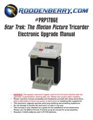
#<strong>PRP1780</strong><br />
<strong>Federation</strong> <strong>Mark</strong> <strong>IX</strong> <strong>Science</strong> <strong>Tricorder</strong><br />
Prop Kit Assembly Manual<br />
The <strong>Roddenberry</strong>.<strong>com</strong> <strong>Federation</strong> <strong>Mark</strong> <strong>IX</strong> <strong>Science</strong> <strong>Tricorder</strong> instructions are for making a<br />
non-functioning “dummy” prop. Graphics for the <strong>Federation</strong> <strong>Science</strong> <strong>Tricorder</strong> include the <strong>Mark</strong> <strong>IX</strong><br />
versions as used on Deep Space Nine and Voyager, and the <strong>Mark</strong> XI version as used in<br />
Star Trek: Nemesis. As a bonus, there’s an alternative data screen “nebula” graphic.<br />
Some model and prop making experience is encouraged due to the <strong>com</strong>plexity of this model of tricorder prop.<br />
To aid in adding an optional electronic circuit board to this <strong>Roddenberry</strong>.<strong>com</strong> kit either now or in the future,<br />
limited electronics preparation instructions are in italics, and some pictures reflect these modifications.<br />
No electronic parts or circuit board installation instructions are included with this kit.
2<br />
#<strong>PRP1780</strong> - <strong>Federation</strong> Ma r k <strong>IX</strong> Sc i e n c e Tr i c or d e r Pr o p Kit As s e m b l y Ma n u a l<br />
PARTS INCLUDED:<br />
• 1 Main body (clear vacu-formed)<br />
• 1 Flap (resin casting) with Flap<br />
Cover Plate<br />
• 1 Bottom frame (laser-cut acrylic)<br />
• 1 Bottom door (laser-cut acrylic)<br />
• 1 each Frame Ends, left and right<br />
(resin)<br />
• 1 Red Square (EMRG button)<br />
• 1 each ID and Name Plates<br />
• 2 Hinges<br />
• 8 Screws for hinges (4 long and<br />
4 short)<br />
• 2 Hinge Retainers<br />
• 4 @ 0-80 Screws for bottom door<br />
• 1 Graphics Sheet (printed vinyl<br />
sheet) to make your choice<br />
of three different science<br />
tricorders, and copper and<br />
black tapes pre-cut with<br />
graphic designs<br />
• 1 each Front Acrylic Tube, long<br />
and short half-round front details<br />
Tools Needed:<br />
• Dremel moto tool with a 1/8” or smaller cutting bit<br />
• Drill with a 1/16” drill bit, and a countersink bit<br />
• Small flat file<br />
• Screwdrivers (small jeweler’s Philips screwdriver for the<br />
0-80 screws, and a larger one for the hinge screws)<br />
• Hobby knife (X-acto brand or similar)<br />
• Plastic straightedge (a ruler or drafter’s triangle –<br />
see-through is helpful but not necessary)<br />
• Artist’s detail paint brush<br />
Supplies Needed:<br />
• Thin acrylic solvent cement (Weld-On #3 or similar)<br />
• Cyanoacrylate (CA) glue, medium gap filling<br />
re<strong>com</strong>mended; and CA cure accelerator<br />
• Bondo plastic filler, and automotive spot putty<br />
• Sandpaper (220-320 grit rough sanding, 400-600 grit finish<br />
sanding)<br />
• Testors Clear Parts Cement<br />
Paints Needed:<br />
• Primer (sandable-type re<strong>com</strong>mended)<br />
• Medium grey metallic, such as Plastikote #1534 Light<br />
Smoke Metallic (big can) or GM#7173 (small can)<br />
• Krylon Flat Black or Semi-Gloss Black<br />
• Black brush paint (a small jar of Tamiya, Testors, or<br />
similar brands, either flat or semi-gloss)<br />
Optional Tools and Materials:<br />
• Soldering iron with solder, wire, red surface-mount size<br />
LED (for EMRG), red surface-mount or T-1 size LED<br />
(for ID)<br />
• 2 @ 75 ohm resistors<br />
• Shrink tube or something to insulate the wiring from<br />
shorting out in your tricorder<br />
• 1/8” drill bit<br />
• Baking soda (bicarbonate of soda)<br />
• Double-sided tape (carpet tape or similar)<br />
• Self-healing cutting pad (available at art supply stores)<br />
• 5-minute epoxy (clear type)
#<strong>PRP1780</strong> - <strong>Federation</strong> Ma r k <strong>IX</strong> Sc i e n c e Tr i c or d e r Pr o p Kit As s e m b l y Ma n u a l 3<br />
Step 1: Wash your resin parts only (not the vacu-formed clear shell) with a chlorine-based cleaner, such<br />
as Ajax or Comet brands, and rinse with water to remove traces of mold release, which might interfere with<br />
the eventual paint finish. Remove the protective sheets from the inside and outside of the main body shell if<br />
present.<br />
Step 2: CA glue the two front frame ends onto the acrylic frame. Note they are a left and right, and the flat<br />
end of each is lined up with the inside ends of the rectangular edge cutout to create a single flat surface.<br />
Step 3: To aid in installing an electronic circuit board on the front face (whether you’re going to put one in<br />
now or are just thinking about it), file the front slot of the frame at an angle as shown, without cutting into<br />
the flats of the frame ends; and don’t go so far as to sharpen the forward edge. A 1/32” to 1/16” flat edge<br />
remaining is okay. With a Dremel tool and a 1/8” or smaller cutting bit, cut slots in the two frame ends. You<br />
may or may not be cutting through the acrylic into the resin.
4<br />
#<strong>PRP1780</strong> - <strong>Federation</strong> Ma r k <strong>IX</strong> Sc i e n c e Tr i c or d e r Pr o p Kit As s e m b l y Ma n u a l<br />
Step 4: Screw the bottom door on the frame. You may need to file the front and back corners of the smaller<br />
inner frame at angles to allow the clear shell to fit properly – test fit the shell to see if you need to remove<br />
material.<br />
Step 5: Try to push the frame forward enough so the front end with its round protrusions lines up with the<br />
surface of the front angle of the body shell. It should appear as one “flat” surface; check with a straightedge<br />
to be sure. Note that the frame edges will stick out beyond the shell on the other three sides.<br />
Step 6: When the shell is seated, glue together with thin Weld-On 3 acrylic cement, which will secure both<br />
the acrylic frame and the clear shell. If you can, glue your parts when placed on a flat surface to avoid<br />
twisting the tricorder body.
#<strong>PRP1780</strong> - <strong>Federation</strong> Ma r k <strong>IX</strong> Sc i e n c e Tr i c or d e r Pr o p Kit As s e m b l y Ma n u a l 5<br />
Step 7: When cured, remove the bottom door, put a bit of masking tape in each of the screw holes (to keep<br />
glue from getting in the holes), sprinkle a little baking soda on the interior seam (don’t use too much or you<br />
won’t get <strong>com</strong>plete glue penetration of the soda powder), and apply some CA glue to the soda. Put a fillet<br />
of glue/soda around the three sides and on the front up to the flat edge of the resin round ends – these are<br />
the weakest points of the shellframe joint. You may also do it the other way – apply a bead of glue first and<br />
then sprinkle some powder on the glue. Remove the tape when you’re finished gluing.<br />
Step 8 (optional electronics preparation): Get 4 lengths of wire about 3” long for each hinge leaf –<br />
24 gauge or smaller will work; they don’t need to be very thick. To make it easier for you in wiring your<br />
tricorder, use two different colors of wire such as red and black, and be sure you’ll remember which wire/<br />
color is positive and which one is negative/ground as you’ll be wiring LEDs into the flap before it gets<br />
sealed, and you’ll need to know the difference when wiring to your main circuit board/battery. Scrape clean<br />
the places on the hinges you’ll be wiring, which will be the opposite side from where the hinge axle is. You<br />
may be scraping a protective clear lacquer from the hinge surface. Solder the wires to the hinges, being<br />
sure you use the same color wire on each hinge so one hinge will have two red wires and the other will<br />
have black, or whatever colors you wish to use.
6<br />
#<strong>PRP1780</strong> - <strong>Federation</strong> Ma r k <strong>IX</strong> Sc i e n c e Tr i c or d e r Pr o p Kit As s e m b l y Ma n u a l<br />
Step 9: Carefully 1/16” drill the four screw holes no more than 1/2” deep in the resin flap for the hinges,<br />
angling these holes slightly so there is no danger of the drill <strong>com</strong>ing out on the outside surface – the EMRG<br />
recessed square is very thin at this point and is easy to break through with a badly angled drill bit. Don’t<br />
angle it too much; otherwise the screws won’t sit well in the hinge holes.<br />
Step 10: For wired hinges, drill a 1/8” center hole in each of the hinge slots, large enough for a wire to be<br />
put through. You may also want to countersink in slight depressions in the flap where you’ve drilled these<br />
center holes that will make room for the wire to hinge solder joints so the hinges can sit flat in their slots.<br />
Step 11: Secure the hinges to the flap with the four long (3/8”) screws, making sure they are both oriented<br />
the same way – whichever way the hinge is (the 2 side or the 3 side) to the flap should be the same on<br />
both hinges. Also make sure the hinge axles appear even on the flap; you will have a lot of problems if<br />
either hinge appears or measures “off.”
#<strong>PRP1780</strong> - <strong>Federation</strong> Ma r k <strong>IX</strong> Sc i e n c e Tr i c or d e r Pr o p Kit As s e m b l y Ma n u a l 7<br />
Step 12: Cut your hinge slots in the body with a Dremel tool, being really careful you don’t go beyond the<br />
confines of the vacu-form depressions. When both slots have been roughed out, use a file to finish the<br />
edges nicely.<br />
Try the flap hinges in the body, you may need to cut away a little more material in order for the hinges to<br />
go in all the way. Also file the slots in such a way that the hinge leafs will sit as flat as possible against the<br />
interior wall of the body.<br />
Step 13: You will need a spacer to lift the flap away from the body at the hinges. You can use 4 or 5<br />
thicknesses of paper for this purpose, or use a shim 10-20 thousandths thick. This will keep from having<br />
the thickness of paint interfering with the proper closing of the flap against the body, which could possibly<br />
damage the paint at that area. Holding the hinges in place with your hand or with a couple pieces of carpet<br />
tape (re<strong>com</strong>mended), try opening and closing the door. You will have to visually determine how the flap<br />
appears on the body in both the open and closed positions and from the front and back.
8<br />
#<strong>PRP1780</strong> - <strong>Federation</strong> Ma r k <strong>IX</strong> Sc i e n c e Tr i c or d e r Pr o p Kit As s e m b l y Ma n u a l<br />
Step 14: When you think you have it right, you’ll need to place a drop of CA glue on both interior hinge<br />
leafs to tack them in place, with some CA accelerator to quickly cure the glue – if you have tape in place,<br />
it’s okay to leave it in. Do not use a lot of glue and be very careful you don’t get any glue in the hinge axles.<br />
If you’re fortunate, the flap will hinge open and close and look even in both positions – this is the one part<br />
of this kit’s assembly that is more art than science and can be very difficult to ac<strong>com</strong>plish. If something is<br />
tweaked in either the open or closed position, you’ll need to break one or both of the joints and try again.<br />
And if you build up too much glue, you’ll have to chip away the old glue and start again. And don’t forget to<br />
look at the hinge leafs screwed into the flap; one of those hinges may be the part that’s off.<br />
If you get any glue in the hinge axles, you will have little choice but to get the pins out of the hinges and<br />
clean them out as best as you can, or you will have to replace the hinges; they are readily available at<br />
hardware stores (replace with a set of 3/4” x 11/16” brass or brass plated hinges).<br />
Step 15: When the flap is in the right place, you may need to add a little more glue to the inside leafs to<br />
eliminate any space between the hinge and the wall so when the screws are tightened the hinges won’t get<br />
out of position. You may also use bondo if you want for this purpose. Drill four holes through the outside<br />
of the body and through the hinge holes -- this will be easy to do because you can see through the clear<br />
materials -- then countersink the holes.
#<strong>PRP1780</strong> - <strong>Federation</strong> Ma r k <strong>IX</strong> Sc i e n c e Tr i c or d e r Pr o p Kit As s e m b l y Ma n u a l 9<br />
Step 16: Using the hinge retainers provided, screw in the four short (1/4”) screws to finish assembling the<br />
hinges to the main body shell.<br />
Be careful with the wires when tightening the screws! If a wire should break, you’ll have to remove the<br />
hinges in order to resolder them, so be sure you have good solder joints before proceeding with assembly.<br />
Step 17: The red EMRG square is about twice as long as it needs to be in the tricorder; it should be about<br />
3/16” to 7/32” in length. Cut off, sand, and/or file away the excess from the opposite end of the good flat<br />
square end – this will be very glossy and either rounded or caved in <strong>com</strong>pared to the rest of the surfaces.<br />
Place the red square piece into the EMRG hole in the flap, using some sort of flat tool (a scrap piece of<br />
plastic or a tool or ruler) on the outside so the square doesn’t stick out beyond the plane of the flat surface.<br />
Then lightly CA glue the square in place from the inside. Once you have a seal where glue won’t leak out to<br />
the outside, add more glue for strength.<br />
See Step 18 on the next page for an alternate option...
10<br />
#<strong>PRP1780</strong> - <strong>Federation</strong> Ma r k <strong>IX</strong> Sc i e n c e Tr i c or d e r Pr o p Kit As s e m b l y Ma n u a l<br />
Step 18: As an alternative, you could cut away excess red square material from the inside with a Dremel<br />
tool after gluing onto the flap.<br />
You might need to sand away more of the red square from the inside after gluing to make more room for an<br />
LED.<br />
Step 19: Drill a 1/8” hole in the ID square so an LED can shine out of it.<br />
Step 20: For wiring two LEDs in the flap, place the LEDs where you want them in the flap and glue so<br />
they don’t move. Solder to one of the leads of each LED (either both the positive or the negative leads) a<br />
resistor of 75 ohms. Solder both LED positives and both LED negatives together, then solder your positive<br />
hinge wire to the positive LEDs end, and do the same for the negative hinge wire to the negative LEDs<br />
end. If you notice the picture, the red hinge wire is connected to the junction of the two resistors. Test your<br />
circuit using a 3 to 4.5V battery source with the wires and try it out with the flap open; it should light up. If it<br />
doesn’t and you know the circuit is otherwise operating when directly connecting the battery source to the<br />
circuit at the flap side of the tricorder, it’s possible there’s something in the hinges which is preventing good<br />
electrical contact, and you’ll have to work with it as best you can.
#<strong>PRP1780</strong> - <strong>Federation</strong> Ma r k <strong>IX</strong> Sc i e n c e Tr i c or d e r Pr o p Kit As s e m b l y Ma n u a l 11<br />
Step 21: You will also need to glue a magnet in the slot on the flap’s edge if you’re building up an electronic<br />
tricorder containing a reed switch, and you may need to dremel away material for the magnet to go in<br />
without it sticking out. Depending on the circuit board, you might have to make a new hole for the magnet<br />
to activate the switch.<br />
Step 22: CA glue the cover plate on the flap. You may need to sand the ID and nameplates thinner (the<br />
graphic should be slightly inset to the flap surface) before gluing these plates on. They are also irregular<br />
shapes, so test them first before permanently gluing them.<br />
Step 23: Apply bondo on the entire surface of the flap cover plate (do not bondo the ID or tricorder name<br />
flap edge plates -- leave those alone -- they should be slightly inset) and sand until the surface is smooth<br />
and flat with a sheet of sandpaper on a flat table. Be careful you don’t sand too much, especially at the flap<br />
edge. If you have any visible spots that are not filled, bondo again.
12<br />
#<strong>PRP1780</strong> - <strong>Federation</strong> Ma r k <strong>IX</strong> Sc i e n c e Tr i c or d e r Pr o p Kit As s e m b l y Ma n u a l<br />
Step 24: Sand or file the protruding edge on the frame all the way around so it contours with the body<br />
nicely. 120/180-grit rough sandpaper will work nicely for this, followed by 220/320-grit. If there is any<br />
webbing present on the vacu-formed main shell that’s sticking out from the rest of the surface, it will<br />
manifest itself the most on the back corners below the hinges; so you’ll need to sand that away and<br />
possibly add a little CA glue/baking soda to build the wall thickness back up on the inside.<br />
Step 25: When it all looks good, apply bondo or spot putty to the frame/shell joint all around, and sand until<br />
smooth. Put some masking tape on the hinge axles and bondo the hinge holes on the body and the hinges<br />
on the flap, making sure not to get any filler on the axles, and sand until smooth. On the front end, avoid<br />
sanding too much of the round protrusion surface. You shouldn’t have any flat spots on those pieces where<br />
the round tube will go on in the front slot, but you do want to contour the corners so they’re nicely rounded<br />
(see pictures later on).
#<strong>PRP1780</strong> - <strong>Federation</strong> Ma r k <strong>IX</strong> Sc i e n c e Tr i c or d e r Pr o p Kit As s e m b l y Ma n u a l 13<br />
Step 26: Fill in any bad places with more bondo and sand again, and pay some attention to the pointy<br />
edge on the flap; you may need to fill in small bubbles that might be exposed after the flat sanding, and you<br />
will want to “break” the sharp edge by sanding lightly on it until it is no longer sharp to the touch, without<br />
sanding too much and losing the shape.<br />
Step 27: There may be a wide line present on the body near the front of the tricorder that goes all the way<br />
around the body. You will need to scuff this surface and bondo, then sand until smooth.<br />
Also sand the shiny surfaces you’ll be painting on with 220/320-grit, without sanding any depressed areas<br />
where the graphics go.
14<br />
#<strong>PRP1780</strong> - <strong>Federation</strong> Ma r k <strong>IX</strong> Sc i e n c e Tr i c or d e r Pr o p Kit As s e m b l y Ma n u a l<br />
PAINTING:<br />
Step 28: Now you’re ready to start the painting process. Screw the bottom door in place. If you are making<br />
a non-functioning tricorder without light effects, mask the EMRG light square with masking tape then<br />
proceed to paint your first coat of primer. If you are adding electronics or are thinking of adding them later,<br />
you will need to mask all the areas that will have lights showing through, those include the depression on<br />
the angled front, the two depressions on the top, the main body depression, and the EMRG square and ID<br />
lights on the flap. Be sure to make your masking smaller than the depression borders so you won’t have<br />
ugly paint seams showing at your edges when you apply the graphics. Also put some tape in the front slot<br />
of the tricorder so paint can’t get inside.<br />
Step 29: Hang your tricorder with a thin wire hook in such a way that you<br />
can get all of the tricorder with paint – the flap will need to be partially open<br />
so you can spray the hinge area where it will hit when fully open, then spray<br />
the first primer coat. If the hinge is loose where the flap can’t stay put when<br />
partly open, you’ll have to spray the hinged surfaces first and let dry before<br />
spraying the rest of the tricorder.
#<strong>PRP1780</strong> - <strong>Federation</strong> Ma r k <strong>IX</strong> Sc i e n c e Tr i c or d e r Pr o p Kit As s e m b l y Ma n u a l 15<br />
Step 30: When dry, check your surface for imperfections; use spot putty or bondo to fill in any bad areas,<br />
sand and primer again until everything looks good to you.<br />
Step 31: Plastikote #7173 was the color originally used on the tricorders, but the manufacturer of the paint<br />
changed the formula over the years so the color is now different today than what was originally available.<br />
Any of the medium metallic grays will look good with the tricorder including the current #7173. A color that<br />
<strong>com</strong>es close to the original is Plastikote #1534 Light Smoke Metallic (in the big can) which the tricorder<br />
pictured here is painted.<br />
Spray your first color coat with your medium metallic gray, and when dry, wet sand with 600-grit sandpaper,<br />
then spray your final coat of paint and allow to cure at least several hours or overnight.<br />
Remove your masking tape if present. You may need to use a hobby knife on the tape edges to avoid paint<br />
on the tape lifting off paint on your prop, being careful of course not to put a knife line on your good finish!<br />
Step 32: Brush paint the EMRG recess detail, being careful you don’t paint the red square. You may go<br />
outside the recess if you like, the graphic will cover it up.
16<br />
#<strong>PRP1780</strong> - <strong>Federation</strong> Ma r k <strong>IX</strong> Sc i e n c e Tr i c or d e r Pr o p Kit As s e m b l y Ma n u a l<br />
Graphics:<br />
Step 33: The graphics go on next. You can apply your choice of the original version DS9/Voyager <strong>Mark</strong><br />
<strong>IX</strong> <strong>Science</strong> graphics (the red graph one), the <strong>Mark</strong> XI graphics as used on Star Trek: Nemesis (the white/<br />
multicolored one), or either set with the alternative display screen pictured below (the “nebula scan”).<br />
Instructions for altering the graphics for a functional tricorder are not included; they go beyond the bounds<br />
of these basic assembly instructions.<br />
Step 34: Place your graphic sheet on a cutting board surface you won’t mind putting knife lines on. A selfhealing<br />
cutting pad available at art supply stores is best. With a plastic straightedge (a ruler or a drafter’s<br />
triangle for example; metal rulers might damage the graphic), hold down your ruler securely and cut your<br />
graphic sheet along all edges (cut out the EMRG white square before cutting the rest of that graphic<br />
from the sheet), use your knife or scissors to round all the corners, and apply as pictured – test exactly<br />
where you want them first before peeling and sticking them on permanently. Once stuck down, you<br />
probably won’t be able to remove or reposition your stickers without damaging them. Also note that the ID<br />
and nameplate graphics are drawn according to the irregular shape of the plates they get stuck to.
#<strong>PRP1780</strong> - <strong>Federation</strong> Ma r k <strong>IX</strong> Sc i e n c e Tr i c or d e r Pr o p Kit As s e m b l y Ma n u a l 17<br />
Step 35: With the main graphic, peel a little away at a time and work from the top edge, and lay it on so<br />
you can avoid leaving bubbles inside the graphic.
18<br />
#<strong>PRP1780</strong> - <strong>Federation</strong> Ma r k <strong>IX</strong> Sc i e n c e Tr i c or d e r Pr o p Kit As s e m b l y Ma n u a l<br />
Finishing touches:<br />
Step 36: Glue on the front half-round detail pieces and the acrylic tube with Testors Clear Parts Cement<br />
(re<strong>com</strong>mended). CA or 5–minute epoxy could also be used, but be sure you’re <strong>com</strong>pletely ready before<br />
you apply CA glue to anything; you won’t get a second chance if the CA glue sets with the part off-location<br />
– practice placing your parts before the gluing. Clear Parts Cement will at least clean off without causing as<br />
much damage to the graphic. You may need to sand flat the bottoms of the two solid half-round pieces, and<br />
file the end(s) of the round tube until it fits in the front slot without it being loose. A little tightness is okay as<br />
long as you can avoid damaging the outer paint there.<br />
Step 37: Scrape a little of the paint away from the protrusions where the tube will go, then apply a drop of<br />
Clear Parts Cement on each end and put in the tube, and align until it looks even in all views. You can also<br />
add more Clear Parts Cement to the length of the tube for added strength, be sure you wipe away excess<br />
glue.<br />
Step 38: Peel and stick on the copper-gold “I – L – square” graphic, and also the black rectangle graphic if<br />
desired.
#<strong>PRP1780</strong> - <strong>Federation</strong> Ma r k <strong>IX</strong> Sc i e n c e Tr i c or d e r Pr o p Kit As s e m b l y Ma n u a l 19<br />
Congratulations, you have successfully assembled a <strong>Roddenberry</strong>.<strong>com</strong> <strong>Federation</strong> <strong>Mark</strong> <strong>IX</strong> <strong>Science</strong> <strong>Tricorder</strong>!<br />
IMPORTANT NOTES:<br />
The physical reproduction by any means known or yet to be invented (including molding and recasting,<br />
reverse-engineering, and stereo lithography scanning and printing) of the <strong>Roddenberry</strong>.<strong>com</strong> <strong>Federation</strong><br />
<strong>Mark</strong> <strong>IX</strong> <strong>Science</strong> <strong>Tricorder</strong> Kit #1780 or its parts and graphics; or reproducing/replicating any pre-existing<br />
products, parts, or graphics is expressly prohibited under U.S. and international copyright and<br />
product protection laws.<br />
Copyright © 2009 <strong>Roddenberry</strong> Productions.<br />
Star Trek and related marks and logos are Trademarks of CBS Studios Inc. All rights reserved.