1 Robotassembly Station MPS 2000 Instructors Edition
1 Robotassembly Station MPS 2000 Instructors Edition
1 Robotassembly Station MPS 2000 Instructors Edition

You also want an ePaper? Increase the reach of your titles
YUMPU automatically turns print PDFs into web optimized ePapers that Google loves.
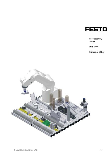
<strong>Robotassembly</strong><br />
<strong>Station</strong><br />
<strong>MPS</strong> <strong>2000</strong><br />
<strong>Instructors</strong> <strong>Edition</strong><br />
© Festo Didactic GmbH & Co. • <strong>MPS</strong> 1
Order no.:<br />
Description: Mechatronics Teachware <strong>Station</strong> <strong>Robotassembly</strong> <strong>MPS</strong> <strong>2000</strong><br />
Designation:<br />
<strong>Instructors</strong> <strong>Edition</strong><br />
Status: July 2003<br />
Author:<br />
Graphics:<br />
Layout:<br />
Wolfgang Eckart, Intercon-Asia<br />
Wolfgang Eckart, Festo Didactic GmbH & Co<br />
Festo Didactic GmbH & Co<br />
© Festo Didactic GmbH & Co., D-73770 Denkendorf, 2003<br />
Internet: www.festo.com/didactic<br />
e-mail: did@festo.com<br />
All rights reserved, including translation rights. No part of this publication may be reproduced or<br />
transmitted in any form or by any means, electronic, mechanical, photocopying, or otherwise, without<br />
the prior written permission of Festo Didactic.
Table of Contents<br />
Table of Contents _______________________________________________________ 1<br />
What is Mechatronics _________________________________________________ 3<br />
Introduction____________________________________________________________ 3<br />
Project overview _____________________________________________________ 6<br />
Commissioning _________________________________________________________ 8<br />
1.1 Analysis – Robot <strong>Station</strong> Components identification ______________ 8<br />
1.2 Analysis – <strong>Robotassembly</strong> <strong>Station</strong> Components identification _____10<br />
1.3 Installation – Robot <strong>Station</strong> Wiring of the System ________________12<br />
1.4 Installation – <strong>Robotassembly</strong> <strong>Station</strong> Wiring of the System ________14<br />
1.5 Analysis– <strong>Robotassembly</strong> <strong>Station</strong> Input and Output adresses______16<br />
1.6 Commissioning – <strong>Robotassembly</strong> <strong>Station</strong> Adjustment of the <strong>Station</strong> 18<br />
1.7 Commissioning – <strong>Robotassembly</strong> <strong>Station</strong> Download Project/Test __23<br />
1.8 Maintenance – Robot <strong>Station</strong> Check the Origin Datas of the Robot__59<br />
1.9 Maintenance – Robot <strong>Station</strong> Reset battery usage time ___________62<br />
1.10 Commissioning – Robot <strong>Station</strong> Operating modes _______________64<br />
1.11 Commissioning – <strong>Robotassembly</strong> <strong>Station</strong> Changing the Parameters 66<br />
Programming__________________________________________________________86<br />
2.1 Programming - Robot <strong>Station</strong> Edit a new Project_________________86<br />
2.2 Teach-In – Robot <strong>Station</strong> Teaching of P1 and P2 _________________93<br />
2.3 Teach-In – Robot <strong>Station</strong> Move to P1 and P2 ___________________100<br />
2.4 Teach-In and Programming – Robot <strong>Station</strong> Upload Positions _____103<br />
2.5 Teach-In – Robot <strong>Station</strong> Change coordinates of P2 _____________112<br />
© Festo Didactic GmbH & Co. • <strong>MPS</strong> 1
Table of Contents<br />
2.6 Teach-In and Programming – Robot <strong>Station</strong> Upload P2 to the PC __116<br />
2.7 Teach-In – Robot <strong>Station</strong> Add a new P3________________________125<br />
2.8 Teach-In and Programming – Robot <strong>Station</strong> Teach-In with PC _____128<br />
2.9 Programming – Robot <strong>Station</strong> Preparation for exercises __________145<br />
2.10 Programming – Robot <strong>Station</strong> PTP movement __________________165<br />
2.11 Programming – Robot <strong>Station</strong> Linear movement ________________174<br />
2.12 Programming – Robot <strong>Station</strong> Modify Speed ___________________178<br />
2.13 Programming – <strong>Robotassembly</strong> <strong>Station</strong> Wait for START __________182<br />
2.14 Programming – <strong>Robotassembly</strong> <strong>Station</strong> If-Then-Else with START ___187<br />
2.15 Programming – <strong>Robotassembly</strong> <strong>Station</strong> Digital I/O ______________190<br />
2.16 Programming – <strong>Robotassembly</strong> <strong>Station</strong> Check- Assembly- Sorting _193<br />
2.17 Programming – <strong>Robotassembly</strong> <strong>Station</strong> Subroutine _____________197<br />
2.18 Project – <strong>Robotassembly</strong> <strong>Station</strong> I/O– communication Basics _____202<br />
2.19 Project – <strong>Robotassembly</strong> <strong>Station</strong> Check and Rejection ___________206<br />
Trouble Shooting _____________________________________________________210<br />
3.1 Trouble Shooting –<strong>Robotassembly</strong> <strong>Station</strong>_____________________210<br />
2 © Festo Didactic GmbH & Co. • <strong>MPS</strong>
Introduction<br />
What is Mechatronics<br />
Mechatronics is a comprehensive combination of Technologies and is mostly<br />
mentioned as a new way of thinking and learning and not as a “stand-alone”<br />
technology.<br />
The technological part of Mechatronics could be called Automation Technology.<br />
Structure of Mechatronics<br />
The structure of Mechatronics training is divided into three levels:<br />
© Festo Didactic GmbH & Co. • <strong>MPS</strong> 3
Introduction<br />
The Basic Training in the single technologies is another part of training. In the<br />
following you will see some examples of the different levels:<br />
Totally Integrated System<br />
Partly Integrated Systems<br />
Basic Technologies<br />
4 © Festo Didactic GmbH & Co. • <strong>MPS</strong>
Introduction<br />
Basically in Automation and Mechatronics training, the contents should cover the<br />
following learning steps, or functions within a company:<br />
Commissioning:<br />
Programming:<br />
Trouble Shooting:<br />
Analyse a system, Installation&Commissioning<br />
Programming single <strong>Station</strong>, Communication with other <strong>Station</strong>s<br />
Programming Errors, Trouble Shooting in the Process<br />
which are covered within the following projects.<br />
Further on this Teachware is based on the idea of a Flexible Manufacturing System –<br />
FMS, this means, this station should be and is connected to another station, called<br />
Previous <strong>Station</strong> within this Teachware. Because of the mechanical structure of the<br />
station and the Robot arm, there is no other function connected after. The<br />
<strong>Robotassembly</strong> <strong>Station</strong> is mostly connected to the Closed Loop Conveyor system,<br />
the centre station within a Flexible Manufacturing System – FMS.<br />
© Festo Didactic GmbH & Co. • <strong>MPS</strong> 5
Introduction<br />
Project overview<br />
The following table give you an overview about all projects within this<br />
documentation in the structure of:<br />
Commissioning:<br />
Programming:<br />
Trouble Shooting:<br />
Analysis (Analyse a system) and<br />
Installation (Cabling of the system)<br />
Commissioning (Adjustment work and test of the process)<br />
Maintenance (Origin Data and Rest Battery usage time)<br />
Teach-In (Teaching of positions with Teach-Box and PC)<br />
Programming (Programming single <strong>Station</strong> and<br />
Project (Communication with other <strong>Station</strong>s)<br />
Process * (Trouble Shooting in the Process)<br />
The table also mention the time which is necessary to work out the respective<br />
project. This time is based on experience with participants coming with no<br />
knowledge about the <strong>MPS</strong>-<strong>Station</strong>s and programming a Mitsubishi Robot RV-2AJ.<br />
*<br />
Regarding the Process-Trouble Shooting, there is no big difference in time between<br />
the single troubles-based on experience. We can say, that each trouble needs<br />
around 1,5 hour including the preparation and test of the error by the instructor and<br />
if the participants follow the three steps carefully and doing the documentation,<br />
which is very important.<br />
This structure allows you to put your specific workshop together according to your<br />
needs and your learning targets.<br />
This Teachware is also divided into Robot <strong>Station</strong> and <strong>Robotassembly</strong> <strong>Station</strong>:<br />
Robot <strong>Station</strong><br />
<strong>Robotassembly</strong> <strong>Station</strong><br />
6 © Festo Didactic GmbH & Co. • <strong>MPS</strong>
Introduction<br />
Learning Step Designation Project Description Proj.. Page Time<br />
Commissioning<br />
Commissioning<br />
Commissioning<br />
Commissioning<br />
Commissioning<br />
Commissioning<br />
Commissioning<br />
Commissioning<br />
Commissioning<br />
Commissioning<br />
Commissioning<br />
Programming<br />
Programming<br />
Programming<br />
Programming<br />
Programming<br />
Programming<br />
Programming<br />
Programming<br />
Programming<br />
Programming<br />
Programming<br />
Programming<br />
Programming<br />
Programming<br />
Programming<br />
Programming<br />
Programming<br />
Programming<br />
Programming<br />
Analysis<br />
Robot <strong>Station</strong>-Components identification:<br />
description of the function of some components used within the stations<br />
1.1 8 1,5 h<br />
Analysis<br />
<strong>Robotassembly</strong> <strong>Station</strong>-Components identification:<br />
description of the function of some components used within the stations<br />
1.2 10 1,5 h<br />
Installation<br />
Robot <strong>Station</strong>-Wiring of the system:<br />
cable connection of the Robot, Drive Unit, Teach-Box and Interface (RIA)<br />
1.3 12 0,5 h<br />
Installation<br />
<strong>Robotassembly</strong> <strong>Station</strong>-Wiring of the system:<br />
cable connection of the Robot, Assembly, Drive Unit, Teach-Box and (RIA)<br />
1.4 14 1,0 h<br />
Analysis<br />
<strong>Robotassembly</strong> <strong>Station</strong>-In-and Output addresses:<br />
find out the hardwareaddresses of in- and outputs in the technical docum.<br />
1.5 16 1,5 h<br />
Commissioning<br />
<strong>Robotassembly</strong> <strong>Station</strong>-Adjustment of the <strong>Station</strong>:<br />
check the adjustment all sensors, pneumatic and mechanical components<br />
1.6 18 3,0 h<br />
Commissioning<br />
<strong>Robotassembly</strong> <strong>Station</strong>-Download Project and Test:<br />
download the project-program and positions and test the function<br />
1.7 23 2,0 h<br />
Maintenance<br />
Robot <strong>Station</strong>-Check the Origin Datas:<br />
download the project-program and positions and test the function<br />
1.8 59 0,5 h<br />
Maintenance<br />
Robot <strong>Station</strong>-Reset the Battery usage time:<br />
download the project-program and positions and test the function<br />
1.9 62 0,5 h<br />
Commissioning<br />
Robot <strong>Station</strong>-Operating modes of the Drive Unit and Teach-Box:<br />
download the project-program and positions and test the function<br />
1.10 64 0,5 h<br />
Commissioning<br />
<strong>Robotassembly</strong> <strong>Station</strong>-Changing the Parameters:<br />
check/change parameters for the defined in- and output functions<br />
1.11 66 0,5 h<br />
Programming<br />
Robot <strong>Station</strong>-Edit a new Project:<br />
edit a new Project with the Project-Wizard<br />
2.1 86 0,5 h<br />
Teach-In<br />
Robot <strong>Station</strong>-Teaching of P1 and P2:<br />
teaching and save of 2 Robot positions with the Teach-Box<br />
2.2 93 1,0 h<br />
Teach-In<br />
Robot <strong>Station</strong>-Move to P1 and P2:<br />
move the Robot to the teached positions using the Teach-Box<br />
2.3 100 0,5 h<br />
Teach-In/Progr.<br />
Robot <strong>Station</strong>-Upload positions to the PC:<br />
upload the teached positions to the Project (PC) and save<br />
2.4 103 0,5 h<br />
Teach-In<br />
Robot <strong>Station</strong>-Change coordinates of P2:<br />
change the coordinates of P2 by direct input of the X,Y,Z,A,B-values<br />
2.5 112 1,0 h<br />
Teach-In/Progr.<br />
Robot <strong>Station</strong>-Upload P2 to the PC:<br />
upload the changed position P2 to the Project (PC) and save<br />
2.6 116 0,5 h<br />
Teach-In<br />
Robot <strong>Station</strong>-Add a new P3:<br />
add a new position P3 using the Teach-Box<br />
2.7 125 0,5 h<br />
Teach-In/Progr.<br />
Robot <strong>Station</strong>-Change coordinates of P2:<br />
change the coordinates of P2 by direct input using the Robot-program (PC)<br />
2.8 128 1,0 h<br />
Teach-In/Progr.<br />
Robot <strong>Station</strong>-Preparation of exercises:<br />
edit a new Project, delete the Drive Unit, planning of positions<br />
2.9 145 0,5 h<br />
Programming<br />
Robot <strong>Station</strong>-Point-to-Point (PTP) movement:<br />
Pick and Place exercise in PTP-movement<br />
2.10 165 2,0 h<br />
Programming<br />
Robot <strong>Station</strong>-Linear movement:<br />
Pick and Place exercise in Linear movement<br />
2.11 174 0,5 h<br />
Programming<br />
Robot <strong>Station</strong>-Modify speed:<br />
Pick and Place in PTP and Linear movement with different speed<br />
2.12 178 1,0 h<br />
Programming<br />
<strong>Robotassembly</strong> <strong>Station</strong>-Wait for START:<br />
start the sequence by pressing the Start-button on the Control Panel<br />
2.13 182 1,5 h<br />
Programming<br />
<strong>Robotassembly</strong> <strong>Station</strong>-If-Then-Else with START:<br />
like Project 2.14, but with the command If-Then-Else instead of Wait<br />
2.14 187 1,5 h<br />
Programming<br />
<strong>Robotassembly</strong> <strong>Station</strong>-Digital I/O:<br />
start the sequence with Start, check if a workpiece is in place<br />
2.15 190 2,0 h<br />
Programming<br />
<strong>Robotassembly</strong> <strong>Station</strong>-Check-Assembly-Sorting:<br />
process check material, assemble a piston rod and sorting in the feeder<br />
2.16 193 6,0 h<br />
Programming<br />
<strong>Robotassembly</strong> <strong>Station</strong>-Check-Assembly-Sorting:<br />
like Project 2.16, but with assembly of a spring using a Subroutine<br />
2.17 197 5,0 h<br />
Project<br />
<strong>Robotassembly</strong> <strong>Station</strong>-I/O-communication Basics<br />
basics of input/output communication between different controllers<br />
2.18 202 3,0 h<br />
Project<br />
<strong>Robotassembly</strong> <strong>Station</strong>-Check and Rejection<br />
take a workpiece from Previous <strong>Station</strong>, check material, reject black<br />
2.19 206 6,0 h<br />
Trouble Shooting Process Maintenance Trouble Shooting14 Process-Errorstime for each approx. 3.1 210 90min<br />
© Festo Didactic GmbH & Co. • <strong>MPS</strong> 7
Commissioning<br />
1.1 Analysis –<br />
Robot <strong>Station</strong><br />
Components<br />
identification<br />
Please list up all the “sensors” and “actuators” shown in the picture below (1 – 3).<br />
Name the elements with identification in the wiring diagram/pneumatic plan and<br />
describe shortly their function generally (not the function within the system).<br />
Information<br />
Please use the technical manual-data sheets, pneumatic plan and wiring diagrams.<br />
Please refer to the example (Ex.1, but not shown in the picture) mentioned below in<br />
the table of the execution work-sheet. Please follow the numbers (1 – 3) shown in<br />
the pictures below.<br />
Instructor: This exercise using the Robot <strong>Station</strong> alone without the Assembly<br />
process. Show one example to the participants how to find an in- and output in the<br />
wiring diagrams and how to find the data sheet using the order number printed on<br />
the element itself. Show the participants at the station itself which components<br />
they have to identify, because the example is not shown within the picture.<br />
© Festo Didactic GmbH & Co. • <strong>MPS</strong> 8
Commissioning<br />
Planning<br />
Please plan your project within the whole team carefully. Use the technical manual<br />
and the real station to do this project. Please describe the function of the element in<br />
general, not within the signal- and material flow of the station. To find the datasheet<br />
of the elements, please see the list of components first and check the order<br />
no. printed on the element itself.<br />
The time to finish this project should be around 1,5 hours.<br />
Execution/Documentation<br />
Please complete the list regarding the elements shown in the pictures above.<br />
No. Name Ident. Description Page #<br />
Ex.1<br />
Opto-<br />
-IP_FL<br />
Optoelectronic sensor Receiver, PNP with<br />
SOEG-E-Q30-RS-S-2L<br />
electronic<br />
fibre optic cable connection, 24 VDC,<br />
Robot: inputs<br />
sensor<br />
receive an optical signal if another<br />
Receiver<br />
station is available and sending an<br />
optical signal<br />
No. Name Ident. Description Page #<br />
1 Single<br />
1Y<br />
5/2-Single solenoid valve, 24 VDC,<br />
CPE-10-M1H-5L-M7<br />
Solenoid<br />
compact valve performance, connection<br />
Robot: inputs<br />
valve<br />
M7, to actuate the Robot-gripper, normal<br />
Robot: pneumatic<br />
position of the gripper is closed, open by<br />
actuating the valve-solenoid<br />
2 Fiber optic<br />
Part_AV<br />
Fibre optical device Sender and Receiver,<br />
SOEG-L-Q30-P-A-S-2L<br />
device<br />
PNP, reflex switch triggering, 24 VDC,<br />
Robot: inputs<br />
send the information “a workpiece is<br />
inside the workpiece mounting” to the<br />
Drive Unit of the Robot<br />
3 Parallel<br />
1A1<br />
Pneumatic parallel gripper, self centring,<br />
HGP-10-A-R<br />
gripper<br />
internal or external use, double acting<br />
Robot: pneumatic<br />
cylinder, 10 mm gripping distance,<br />
proximity switches for end-position<br />
detection, gripping force nominal 40 N<br />
close and 47 N open<br />
© Festo Didactic GmbH & Co. • <strong>MPS</strong> 9
Commissioning<br />
1.2 Analysis –<br />
<strong>Robotassembly</strong><br />
<strong>Station</strong><br />
Components<br />
identification<br />
Please list up all the “sensors” and “actuators” shown in the picture below (1 – 3).<br />
Name the elements with identification in the wiring diagram/pneumatic plan and<br />
describe shortly their function generally (not the function within the system).<br />
Information<br />
Please use the technical manual-data sheets, pneumatic plan and wiring diagrams.<br />
Please refer to the example (Ex.1, but not shown in the picture) mentioned below in<br />
the table of the execution work-sheet. Please follow the numbers (1 – 3) shown in<br />
the pictures below.<br />
Instructor: This exercise using the Robot and the Assembly <strong>Station</strong>. Show one<br />
example to the participants how to find an in- and output in the wiring diagrams<br />
and how to find the data sheet using the order number printed on the element<br />
itself. Show the participants at the station itself which components they have to<br />
identify, because the example is not shown within the picture.<br />
10 © Festo Didactic GmbH & Co. • <strong>MPS</strong>
Commissioning<br />
Planning<br />
Please plan your project within the whole team carefully. Use the technical manual<br />
and the real station to do this project. Please describe the function of the element in<br />
general, not within the signal- and material flow of the station. To find the datasheet<br />
of the elements, please see the list of components first and check the order<br />
no. printed on the element itself.<br />
The time to finish this project should be around 1,5 hours.<br />
Execution/Documentation<br />
Please complete the list regarding the elements shown in the pictures above.<br />
No. Name Ident. Description Page #<br />
Ex.1<br />
Opto-<br />
-A1 Optoelectronic sensor Sender, PNP with<br />
SOEG-S-Q30-S-L<br />
electronic<br />
fibre optic cable connection, 24 VDC,<br />
Robot: inputs<br />
sensor<br />
send an optical signal to another station<br />
Sender<br />
(to an optoelectronic receiver)<br />
No. Name Ident. Description Page #<br />
1 Double acting<br />
cylinder<br />
2A1 Double acting pneumatic ISO-cylinder, 8<br />
mm diameter and 80 mm stroke, with<br />
magnet ring to activate proximity<br />
switches, with flow control valves to<br />
adjust the piston rod speed, normal<br />
position front end position<br />
DSNU-8-80-P-A<br />
Robot: pneumatic<br />
2 Micro switch 1S1 manual switch, changeover contact,<br />
activated by the spring feeding cylinder<br />
mechanically, send the information<br />
“spring is in place” to the PLC-input<br />
S-3-E<br />
Robot: inputs<br />
3 Proximity<br />
2B2<br />
Reed switch electrical, normally open<br />
SME-8-S-LED-24<br />
switch<br />
contact, activated by a magnet ring in the<br />
<strong>Station</strong>: inputs<br />
piston rod of the cylinder, send the<br />
<strong>Station</strong>: pneumatic<br />
information “piston rod of the cylinder is<br />
in front position” to the Robot Drive-Unit<br />
© Festo Didactic GmbH & Co. • <strong>MPS</strong> 11
Commissioning<br />
1.3 Installation –<br />
Robot <strong>Station</strong><br />
Wiring of the<br />
System<br />
Please analyze the cable connections in your station and complete the drawing on<br />
the next page (Execution and Documentation).<br />
Information<br />
Please fill out all in the graphic and draw the connections. Use the real station to<br />
check the connections.<br />
Instructor: Leave the cables all connected to help the participants.<br />
Planning<br />
Please follow the explanations of the instructor first and then plan your activities<br />
step-by-step. Use the real station to find out all connections and identifications. Use<br />
also the technical documentation.<br />
The time to finish this project should be around 0,5 hours.<br />
12 © Festo Didactic GmbH & Co. • <strong>MPS</strong>
Commissioning<br />
Execution/Documentation<br />
© Festo Didactic GmbH & Co. • <strong>MPS</strong> 13
Commissioning<br />
1.4 Installation –<br />
<strong>Robotassembly</strong><br />
<strong>Station</strong><br />
Wiring of the<br />
System<br />
Please analyze the cable connections in your station and complete the drawing on<br />
the next page (Execution and Documentation).<br />
Information<br />
Please fill out all in the graphic and draw the connections. Use the real station to<br />
check the connections.<br />
Instructor: Leave the cables all connected to help the participants.<br />
Planning<br />
Please follow the explanations of the instructor first and then plan your activities<br />
step-by-step. Use the real station to find out all connections and identifications. Use<br />
also the technical documentation.<br />
The time to finish this project should be around 1,0 hours.<br />
14 © Festo Didactic GmbH & Co. • <strong>MPS</strong>
Commissioning<br />
Execution/Documentation<br />
© Festo Didactic GmbH & Co. • <strong>MPS</strong> 15
Commissioning<br />
1.5 Analysis–<br />
<strong>Robotassembly</strong><br />
<strong>Station</strong><br />
Input and Output<br />
adresses<br />
Please complete the below mentioned list of input- and output addresses of the<br />
<strong>Station</strong> connected to the Drive Unit via the Robot Interface Box (RIA-Box).<br />
Information<br />
To find out the addresses please use the technical manual-wiring diagram for the<br />
station and the Control Panel.<br />
Instructor: show the participants how to find out an input and an output using the<br />
wiring diagrams. Show them also how to find out the communication in- and<br />
outputs.<br />
Planning<br />
Please plan your activities within your team.<br />
The time to finish this project should be around 1,5 hour.<br />
16 © Festo Didactic GmbH & Co. • <strong>MPS</strong>
Commissioning<br />
Execution/Documentation<br />
Please complete the list of the inputs and outputs of your station.<br />
I/O <strong>Station</strong><br />
Address Ident. Description<br />
M_IN(1)<br />
M_IN(2)<br />
M_IN(8)<br />
M_IN(9)<br />
M_IN(10)<br />
M_IN(11)<br />
M_IN(12)<br />
M_IN(13)<br />
M_IN(14)<br />
M_IN(15)<br />
M_OUT(8)<br />
M_OUT(9)<br />
Out 10-15<br />
Optical sensor in gripper red/alu=1, black/no workpiece=0<br />
Optical sensor for measuring orientation<br />
Feeder of springs in back position<br />
Feeder of springs in front position<br />
Feeder of cover in front position<br />
Feeder of cover in back position<br />
Spring is available after feeding<br />
No cover at gripping position after feeding<br />
Feeder for covers is empty<br />
IP following station available<br />
Feeding of a spring<br />
Feeding of a cover<br />
Not connected<br />
I/O Control Panel<br />
Address Ident. Description<br />
M_IN(3)<br />
M_IN(4)<br />
M_IN(5)<br />
M_OUT(0)<br />
M_OUT(1)<br />
M_OUT(2)<br />
M_OUT(3)<br />
START button<br />
STOP button<br />
RESET button<br />
START light<br />
RESET light<br />
Special function Q1 light<br />
Special function Q2 lamp light<br />
I/O Communication<br />
Address Ident. Description<br />
M_IN(7)<br />
M_OUT(4)<br />
M_OUT(5)<br />
M_OUT(6)<br />
M_OUT(7)<br />
Communication with Previous <strong>Station</strong> – Input for start assembly<br />
Error Code Bit 0 for feedback to Previous <strong>Station</strong><br />
Error Code Bit 1 for feedback to Previous <strong>Station</strong><br />
Robot Assembly <strong>Station</strong> is in process<br />
Robot Assembly <strong>Station</strong> is ready to receive a workpiece<br />
© Festo Didactic GmbH & Co. • <strong>MPS</strong> 17
Commissioning<br />
1.6 Commissioning –<br />
<strong>Robotassembly</strong><br />
<strong>Station</strong><br />
Adjustment of the<br />
<strong>Station</strong><br />
Please check the adjustment of all sensors, the mechanical components and the<br />
pneumatical components of your station to prepare the test of the whole process.<br />
Check also the cable connections and the power- and air-supply.<br />
Information<br />
To find out the function and location of the sensors and pneumatical components<br />
please use the technical documentation. The inputs can also be checked directly at<br />
the LED of the I/O-interface XMA2 of the Assembly <strong>Station</strong>. To move pneumatic<br />
actuators, please switch off the air-pressure and move them manually by hand.<br />
Please be very careful, move the actuators back before switching on the air-pressure<br />
again.<br />
In the following please find some important informations regarding pneumatic<br />
actuators and their triggering. These informations are basically.<br />
• 5 = number of connections (1, 3, 4, 2 and 5)<br />
• 2 = 2 switching positions (2 rectangles)<br />
The connections have the following functions:<br />
1(P) = air connection (supply)<br />
2(B) = output B for backward stroke<br />
3(S) = connection exhaust air of forward stroke<br />
4(A) = output A for forward stroke<br />
5(S) = connection exhaust air of backward stroke<br />
In the following drawing you can find letters in brackets behind the standardized<br />
designation of the connections (1, 3, 4, 2 and 5). These letters are former<br />
designations, one can still find them on old elements.<br />
18 © Festo Didactic GmbH & Co. • <strong>MPS</strong>
Commissioning<br />
short<br />
power<br />
signal<br />
(24VDC)<br />
connected to y2<br />
4(A) 2(B)<br />
4(A) 2(B)<br />
14 12 14<br />
12<br />
y2<br />
5(S) 3(R)<br />
1(P)<br />
y3<br />
y2<br />
5(S) 3(R) y3<br />
1(P)<br />
short<br />
power<br />
signal<br />
(24VDC)<br />
connected to y3<br />
Activation of single/double solenoid valve:<br />
14<br />
y1<br />
4(A)<br />
2(B)<br />
5(S)<br />
1(P)<br />
3(R)<br />
power<br />
(24VDC)<br />
connected to Y1<br />
14<br />
y1<br />
4(A)<br />
2(B)<br />
5(S)<br />
1(P)<br />
3(R)<br />
Activation of a single solenoid valve:<br />
Single solenoid<br />
Double solenoid<br />
14<br />
y1<br />
4(A)<br />
2(B)<br />
5(S)<br />
1(P)<br />
3(R)<br />
4(A) 2(B)<br />
14 12<br />
y2 5(S) 3(R) y3<br />
1(P)<br />
Activation of a double solenoid valve:<br />
© Festo Didactic GmbH & Co. • <strong>MPS</strong> 19
Commissioning<br />
Instructor: Work-out the basics of pneumatics first and explain the functions of<br />
pneumatic valves and actuators. Show the participants how to move pneumatic<br />
actuators by hand without air-pressure, or activating the manual detection button<br />
on the valve itself with air-pressure. Show an example how to adjust a sensor to<br />
define the back or front position of a cylinder and how to adjust the speed of a<br />
pneumatical actuator. Provide the necessary tools.<br />
Deadjust the following sensors (bold)<br />
I/O <strong>Station</strong><br />
Address Ident. Description<br />
M_IN(1)<br />
M_IN(2)<br />
M_IN(8)<br />
M_IN(9)<br />
M_IN(10)<br />
M_IN(11)<br />
M_IN(12)<br />
M_IN(13)<br />
M_IN(14)<br />
M_IN(15)<br />
M_OUT(8)<br />
M_OUT(9)<br />
Out 10-15<br />
Optical sensor in gripper red/alu=1, black/no workpiece=0<br />
Optical sensor for measuring orientation<br />
Feeder of springs in back position<br />
Feeder of springs in front position<br />
Feeder of cover in front position<br />
Feeder of cover in back position<br />
Spring is available after feeding<br />
No cover at gripping position after feeding<br />
Feeder for covers is empty<br />
IP following station available<br />
Feeding of a spring<br />
Feeding of a cover<br />
Not connected<br />
Please don´t change any mechanical position!!!<br />
Disconnect the power- and air supply and disconnect all cable connections.<br />
Remove also the Control Panel from the trolley. Remove all workpieces from the<br />
<strong>Station</strong>. Change the speed of the pneumatical actuators at the one-way flow<br />
control valves.<br />
20 © Festo Didactic GmbH & Co. • <strong>MPS</strong>
Commissioning<br />
Work out together with the participants the general steps of Installation. The<br />
conditions for this example shall be:<br />
• all cable connections are removed<br />
• no power supply connection, no air-pressure supply<br />
• the Control Panel is removed<br />
1. check the adjustment of mechanical components<br />
2. check the adjustment of mechanical actuators holder<br />
3. assemble removed components (like Control Panel)<br />
4. cable connections (Drive Unit, Teach-Box, RIA, Control Panel, Communication)<br />
5. connect all power supplies<br />
6. check the adjustment of sensor holders<br />
7. check the adjustment of sensors in the holders<br />
8. check the adjustment of sensitivity of sensor<br />
9. tubing connections<br />
10. connect all air-pressure supplies (careful! turn pressure down before)<br />
11. check the adjustment of the speed of pneumatic actuators<br />
12. connect the stations together<br />
13. communication connection<br />
© Festo Didactic GmbH & Co. • <strong>MPS</strong> 21
Commissioning<br />
Planning<br />
Please plan your activities within your team. Check the inputs in the wiring diagram<br />
and at the RIA-Box frontside. Follow the steps worked out together with the<br />
Instructor.<br />
The time to finish this project should be around 3,0 hour.<br />
Execution/Documentation<br />
Write down the single steps and all useful informations. Write down your single<br />
steps you did to proceed. Use the tables to proceed.<br />
Step No.: Description Check<br />
1 check the adjustment of mechanical components<br />
2 check the adjustment of mechanical actuators holder<br />
3 assemble removed components (Control Panel…)<br />
4 cable connections (Drive Unit, Control Panel, …..)<br />
5 connect all power supplies<br />
6 check the adjustment of sensor holders<br />
7 check the adjustment of sensors in the holders<br />
8 check the adjustment of sensitivity of sensor<br />
9 tubing connections<br />
10 connect all air-pressure supplies (careful! turn pressure down)<br />
11 check the adjustment of the speed of pneumatic actuators<br />
12 connect the stations together<br />
13 communication connection<br />
22 © Festo Didactic GmbH & Co. • <strong>MPS</strong>
Commissioning<br />
1.7 Commissioning –<br />
<strong>Robotassembly</strong><br />
<strong>Station</strong><br />
Download<br />
Project/Test<br />
Please download the project into the Drive Unit and test the full process.<br />
Information<br />
Please make sure that the PC is connected to the Drive Unit with the communication<br />
cable and make sure, the correct serial port COM1/2 is selected within the program,<br />
the power supply of the station is on, air-pressure of around 5 bar is available at<br />
each station, the emergency switch is deactivated (if available). Make sure that the<br />
Drive Unit memory is empty (delete).<br />
Instructor: Show how to delete the contents of the Drive Unit. Show how to check<br />
the serial port connection using the software. Tell the participants, in which<br />
subdirectory they are able to find the project in the following screen shots, the<br />
project is located in:<br />
C:\Dokumente und Einstellungen\Wolfgang Eckart\Eigene Dateien\Eigene<br />
Daten\Teach_gb\Festo\<strong>MPS</strong>_<strong>Robotassembly</strong>_releaseC\Prog_COSIMIR<br />
if you are using the COSIMIR Industrial-software and<br />
C:\Dokumente und Einstellungen\Wolfgang Eckart\Eigene Dateien\Eigene<br />
Daten\Teach_gb\Festo\<strong>MPS</strong>_<strong>Robotassembly</strong>_releaseC\Prog_Cosirop<br />
if you are using the COSIROP-software<br />
but this can be different on your PC.<br />
Explain them step-by-step how to download a project to the Drive Unit. Develop<br />
the process sequence on the white board first this means, what is the process and<br />
how to start it. Which are the Control Panel functions.<br />
Basically all screen shots and PLC-projects are based on two different<br />
programming software versions: COSIMIR Industrial and COSIROP. Please move<br />
the Robot to the position P99 before starting this Project.<br />
Planning<br />
Please follow the description of the Instructor carefully step-by-step. Use the NOTICE<br />
field to write down the single steps to proceed.<br />
The time to finish this project should be around 2,0 hours.<br />
© Festo Didactic GmbH & Co. • <strong>MPS</strong> 23
Commissioning<br />
Execution/Documentation<br />
Follow the single steps of the Instructor. Write down the single steps and all useful<br />
informations into the field NOTICE.<br />
Write down your single steps you did to proceed after checking that the<br />
communication between the PC and the Drive Unit is ok:<br />
1. Check the air-pressure = 5 bar<br />
2. Check cable connection plug should be locked<br />
3. Refill all feeders with workpieces and empty the workpiece mountings<br />
4. Release Emergency switch at the Drive Unit and at the Teach-Box<br />
5. Switch the key on the Teach-Box to DISABLE<br />
6. Switch the key on the Drive Unit to AUTO (EXT) position<br />
7. Switch on the Drive Unit and the Power Supply of the <strong>Station</strong><br />
8. Change the offset speed (display o ) to 100 by using the UP or<br />
DOWN button on the Drive Unit<br />
9. Open the Project on the PC and delete all contents of the Drive Unit<br />
10. Download the Project to the Drive Unit<br />
11. Switch the key on the Drive Unit to AUTO (OP) position<br />
12. Choose the program NO. 1 on the Drive Unit by pressing the button<br />
CHNG/DISP as long as P.0001 will appear on the screen of the Drive Unit<br />
13. Now please activate the servo motors by pressing the SVO ON buttonplease<br />
wait until the LED of this button is on<br />
14. Now please press the START button of the Drive Unit-LED is on – the<br />
program is now active<br />
15. Press the RESET button on the Control Panel to move the robot to it´s<br />
starting position P99. After reaching P99, the LED of the Reset-button is on<br />
16. To start the process, press the START button of the Control Panel once, the<br />
Reset-LED is off and the Start-LED is on<br />
24 © Festo Didactic GmbH & Co. • <strong>MPS</strong>
Commissioning<br />
During the process, the lights of the Control Panel have the following functions:<br />
• Missing springs will be shown by Special function Q1 light<br />
• Missing covers will be shown by Special function Q2 light<br />
• Missing piston rods will be shown by Special function Q1 and Q2 light<br />
• Please refill the missing parts and press START-button of the Control Panel to<br />
continue with the assembly process<br />
• If the robot is not able to detect the orientation of the base, it will be rejected. If<br />
the robot is not able to detect the orientation of the cover, it will be also rejected<br />
and the LED´s Q1 and Q2 are flashing alternating, this means also to remove the<br />
base by hand – the process will be interrupted. By pressing START-button once,<br />
the LED´s stop flashing and the robot continue with the assembly process<br />
• The maximum amount of rejected workpieces is controlled via a counter inside<br />
the robot-program. If the maximum amount of bad workpieces is exceeded, the<br />
LED´s Q1 and Q2 are flashing alternating and the process will be interrupted.<br />
Empty the rejection magazine and quit by pressing the START-button again. The<br />
process continue<br />
• If there is a vision system available within the FMS to detect good and bad parts,<br />
the robot will reject the bad parts out of the production process<br />
The process can be interrupted by pressing STOP-button at each time the STARTlight<br />
is flashing, continue the assembly process with START-button.<br />
The Program structure is as follow:<br />
The robot program is written in a sequence. There is only one program for<br />
downloading to the drive unit. Peripheral units like valves or sensors are controlled<br />
by the drive unit.<br />
In a main program loop subroutines are executed:<br />
• retrieve workpiece<br />
• insert piston (corresponding to workpiece)<br />
• insert spring<br />
• assemble cover<br />
Simultaneous an interrupt function monitors the STOP button of the control panel. If<br />
activated the program will be paused in any position.<br />
© Festo Didactic GmbH & Co. • <strong>MPS</strong> 25
Commissioning<br />
Following input signals are the communication between the <strong>Robotassembly</strong> <strong>Station</strong><br />
and the Conveyor:<br />
• Robot input bit No. 6 = Start assembly<br />
• Robot output bit No.7 = Assembly ready, workpiece back onto the pallet<br />
• Robot input bit No. 7 = bad part → sort out<br />
The handshake (communication with Conveyor) is following the steps:<br />
The process positions are defined as follow:<br />
Pos. No.:<br />
P1<br />
P2<br />
P3<br />
P4<br />
P5<br />
P6<br />
P9<br />
P99<br />
Description<br />
Retrieve and return position on the Conveyor pallet with red workpiece<br />
Workpiece mounting, teach with cone gauge in inner gripper jaws.<br />
Rotate outer gripper jaws into direction of robot. The gripper jaws<br />
should be parallel to the X-axis of the robot.<br />
Identify workpiece if black/not black with optical sensor in the gripper<br />
Gripping position at feeder for springs<br />
Position at piston pallet, teach with cone gauge in inner gripper jaws<br />
Release position if there is no detection during rotation of workpieces<br />
Gripping position for covers<br />
Waiting position<br />
26 © Festo Didactic GmbH & Co. • <strong>MPS</strong>
Commissioning<br />
Position P1<br />
Position P1<br />
© Festo Didactic GmbH & Co. • <strong>MPS</strong> 27
Commissioning<br />
Position P2<br />
Position P2<br />
28 © Festo Didactic GmbH & Co. • <strong>MPS</strong>
Commissioning<br />
Position P3<br />
Position P3<br />
© Festo Didactic GmbH & Co. • <strong>MPS</strong> 29
Commissioning<br />
Position P4<br />
30 © Festo Didactic GmbH & Co. • <strong>MPS</strong>
Commissioning<br />
Position P5<br />
Position P5<br />
© Festo Didactic GmbH & Co. • <strong>MPS</strong> 31
Commissioning<br />
Position P6<br />
Position P9<br />
32 © Festo Didactic GmbH & Co. • <strong>MPS</strong>
Commissioning<br />
Position P99<br />
© Festo Didactic GmbH & Co. • <strong>MPS</strong> 33
Commissioning<br />
The conditions to download the full project are, that the Drive Unit is connected with<br />
the PC, the Drive Unit is on and the key-switch of the Teach-Box in DISABLE position<br />
and the software (COSIROP or COSIMIR) opened.<br />
How to proceed step 9 and 10 from page 24 to open, delete and download the<br />
project of the full FMS-process with different software is shown on the following:<br />
Before starting the process, please make sure, that the offset speed is 100%. Please<br />
proceed as shown below.<br />
Switch on the Drive Unit and switch the key to AUTO (Op).<br />
1. Press CHNG DISP as long as…<br />
2. …. you can see the actual speed (in % from 10-100 – here 100)<br />
3. increase the speed by pressing UP until 100 is shown in the display<br />
After this, please switch the key-switch on the Drive Unit to AUTO (Ext) and proceed<br />
as shown below.<br />
34 © Festo Didactic GmbH & Co. • <strong>MPS</strong>
Commissioning<br />
COSIROP – open the project solution<br />
File Open (Choose the right directory and click onto the file – here IT_CITRES,<br />
the name can be different within your project) Öffnen<br />
© Festo Didactic GmbH & Co. • <strong>MPS</strong> 35
Commissioning<br />
COSIROP – check the communication port:<br />
Extras Settings Communication Port<br />
36 © Festo Didactic GmbH & Co. • <strong>MPS</strong>
Commissioning<br />
Serial Interface (click onto the selection of Serial Interface if it´s not active already)<br />
© Festo Didactic GmbH & Co. • <strong>MPS</strong> 37
Commissioning<br />
Serial Interface (Window) (Change the Port: to your interface you are using – here<br />
COM1) OK<br />
38 © Festo Didactic GmbH & Co. • <strong>MPS</strong>
Commissioning<br />
COSIROP – connection to the Drive Unit:<br />
Execute Init Connection<br />
© Festo Didactic GmbH & Co. • <strong>MPS</strong> 39
Commissioning<br />
COSIROP – open the Program directory of the contents of the Drive Unit:<br />
Extras Program Directory<br />
40 © Festo Didactic GmbH & Co. • <strong>MPS</strong>
Commissioning<br />
(Make sure all contents are marked) Delete Program OK (follow the screen to<br />
proceed)<br />
© Festo Didactic GmbH & Co. • <strong>MPS</strong> 41
Commissioning<br />
COSIROP – download the original Positions to the Drive Unit:<br />
(Activate the Window with the Positions first) Execute Download PC Robot<br />
42 © Festo Didactic GmbH & Co. • <strong>MPS</strong>
Commissioning<br />
(Type in the Program number 1 into the field Name (“N”) OK (Activate the<br />
Window with the Program after download is finish)<br />
© Festo Didactic GmbH & Co. • <strong>MPS</strong> 43
Commissioning<br />
COSIROP – download the original Program to the Drive Unit:<br />
Execute Download PC Robot<br />
44 © Festo Didactic GmbH & Co. • <strong>MPS</strong>
Commissioning<br />
(Type in the Program name 1 into the field Name (“N”) OK<br />
© Festo Didactic GmbH & Co. • <strong>MPS</strong> 45
Commissioning<br />
COSIROP – start the process:<br />
Execute Program Start<br />
46 © Festo Didactic GmbH & Co. • <strong>MPS</strong>
Commissioning<br />
COSIMIR – open the project solution<br />
File Open (Choose the right directory and click onto the file – here IT_CITRES,<br />
the name can be different within your project) Öffnen<br />
© Festo Didactic GmbH & Co. • <strong>MPS</strong> 47
Commissioning<br />
COSIMIR – check the communication port:<br />
Extras Settings Communication Port<br />
48 © Festo Didactic GmbH & Co. • <strong>MPS</strong>
Commissioning<br />
Serial Interface (click onto the selection of Serial Interface if it´s not active already)<br />
© Festo Didactic GmbH & Co. • <strong>MPS</strong> 49
Commissioning<br />
Serial Interface (Window) (Change the Port: to your interface you are using – here<br />
COM1) OK<br />
50 © Festo Didactic GmbH & Co. • <strong>MPS</strong>
Commissioning<br />
COSIMIR – connection to the Drive Unit:<br />
Execute Init Connection<br />
© Festo Didactic GmbH & Co. • <strong>MPS</strong> 51
Commissioning<br />
COSIMIR – open the Program directory of the contents of the Drive Unit:<br />
Extras Program Directory<br />
52 © Festo Didactic GmbH & Co. • <strong>MPS</strong>
Commissioning<br />
(Make sure all contents are marked) Delete Program OK (follow the screen to<br />
proceed)<br />
© Festo Didactic GmbH & Co. • <strong>MPS</strong> 53
Commissioning<br />
COSIMIR – download the original Positions to the Drive Unit:<br />
(Activate the Window with the Positions first) Execute Download PC Robot<br />
54 © Festo Didactic GmbH & Co. • <strong>MPS</strong>
Commissioning<br />
(Type in the Program number 1 into the field Name (“N”) OK (Activate the<br />
Window with the Program after download is finish)<br />
© Festo Didactic GmbH & Co. • <strong>MPS</strong> 55
Commissioning<br />
COSIMIR – download the original Program to the Drive Unit:<br />
Execute Download PC Robot<br />
56 © Festo Didactic GmbH & Co. • <strong>MPS</strong>
Commissioning<br />
(Type in the Program name 1 into the field Name (“N”) OK<br />
© Festo Didactic GmbH & Co. • <strong>MPS</strong> 57
Commissioning<br />
COSIMIR – start the process:<br />
Execute Program Start<br />
After the process run properly, please delete all contents of the Drive Unit like<br />
mentioned above to prepare the following Programming exercises !!!<br />
58 © Festo Didactic GmbH & Co. • <strong>MPS</strong>
Commissioning<br />
1.8 Maintenance –<br />
Robot <strong>Station</strong><br />
Check the Origin<br />
Datas of the Robot<br />
Please check the Original Datas of the Robot mentioned on the backside of the<br />
connection cover of the Robot arm.<br />
Information<br />
Please open the cover on the backside of the Robot arm first to see the datas.<br />
Because the Robot comes with an absolute positioning system, the “reference”<br />
datas must be defined correctly. This have to be done also at the very first<br />
commissioning of the Robot, or if the batteries of the Robot arm and/or the Drive<br />
Unit have been changed.<br />
1 Origin Datas are on the back side (inside) of the cover<br />
Instructor: Show where the Original datas can be found. Explain about incremental<br />
and absolute positioning system of an Industrial Robot.<br />
© Festo Didactic GmbH & Co. • <strong>MPS</strong> 59
Commissioning<br />
Planning<br />
Please follow the descriptions on the next page very carefully. Please don´t change<br />
any Original datas if they are ok. Switch the key-switch of the Drive Unit to TEACH<br />
position and the key-switch of the Teach-Box to ENABLE. Take the Teach-Box and<br />
press the dead-man-switch permanently as long as you are using it.<br />
The time to finish this project should be around 0,5 hours.<br />
1 Dead-man-switch on the backside of the Teach-Box<br />
60 © Festo Didactic GmbH & Co. • <strong>MPS</strong>
Commissioning<br />
© Festo Didactic GmbH & Co. • <strong>MPS</strong> 61
Commissioning<br />
1.9 Maintenance –<br />
Robot <strong>Station</strong><br />
Reset battery<br />
usage time<br />
Please reset the battery usage time in the Drive Unit using the Teach-Box.<br />
Information<br />
After changing the batteries of the Robot arm (5 batteries) and/or the batteries of<br />
the Drive Unit (1 battery), we have to reset the usage time of it. Please refer to the<br />
Technical documentation of Mitsubishi of how to proceed to change the batteries.<br />
Instructor: Show where batteries are located and how to proceed to change it.<br />
Planning<br />
Please follow the descriptions on the next page very carefully. Switch the key-switch<br />
of the Drive Unit to TEACH position and the key-switch of the Teach-Box to ENABLE.<br />
Take the Teach-Box and press the dead-man-switch permanently as long as you are<br />
using it (this have to be done always using the Teach-Box and is no more mentioned<br />
within the following projects).<br />
The time to finish this project should be around 0,5 hours.<br />
1 Dead-man-switch on the backside of the Teach-Box<br />
62 © Festo Didactic GmbH & Co. • <strong>MPS</strong>
Commissioning<br />
© Festo Didactic GmbH & Co. • <strong>MPS</strong> 63
Commissioning<br />
1.10 Commissioning –<br />
Robot <strong>Station</strong><br />
Operating modes<br />
Please fill out the exercise sheet below. Please mark the corresponding key switch<br />
positions for each task.<br />
Information<br />
The controller has a ‘Mode changeover’ key-switch. The Teach-Box has an<br />
ENABLE/DISABLE key-switch. For each possible operating task it is necessary to turn<br />
the key switches in a specific position.<br />
Instructor: Please proceed the different modes together with the participants.<br />
Planning<br />
Please follow the description of the Instructor carefully. Use the following table to<br />
proceed.<br />
The time to finish this project should be around 0,5 hours.<br />
64 © Festo Didactic GmbH & Co. • <strong>MPS</strong>
Commissioning<br />
Please write down a task for the specified key switch positions. Be aware that<br />
sometimes more than one task is possible for a key switch combination.<br />
Operating Modes of the Mitsubishi Robot RV-2AJ<br />
Name: Wolfgang Eckart Date: 30.06.2003<br />
Project: Commissioning - Operating Modes<br />
Exercise: Operating modes of the Drive Unit and the Teach-Box Sheet 1 of 1<br />
Key switch<br />
Controller<br />
Key switch<br />
Teach Box<br />
Task<br />
AutoOP<br />
TEACH<br />
AutoExt<br />
Disable<br />
Enable<br />
Additional Information<br />
Teach Box X X<br />
Programming with<br />
PC X X<br />
Teach Box X X<br />
TEACH Mode<br />
PC X X<br />
PC X X<br />
Start program with<br />
Controller X X<br />
Teach Box X X<br />
Read parameter with<br />
PC X X X X<br />
Teach Box X X<br />
Write parameter with<br />
PC X X<br />
Teach Box X X<br />
Change speed with<br />
Controller X X<br />
Teach Box X X<br />
Change program with<br />
PC X X<br />
Controller X X<br />
Teach Box X X<br />
Teach positions with<br />
PC X X<br />
Download/upload program from PC X X<br />
Download/upload positions from PC X X<br />
Reboot controller after changing<br />
parameter!<br />
© Festo Didactic GmbH & Co. • <strong>MPS</strong> 65
Commissioning<br />
1.11 Commissioning –<br />
<strong>Robotassembly</strong><br />
<strong>Station</strong><br />
Changing the<br />
Parameters<br />
Please check/deactivate the parameters of START, IOENA, ERRESET, SRVON,<br />
SRVOFF in the Drive Unit<br />
Information<br />
The first in- and outputs of the Drive Unit I/O-port have fixed functions, defined by<br />
parameters. Because we have to use this in- and outputs for the full process, we<br />
have to deactivate the function inside the Drive Unit. Switch the key-switch of the<br />
Teach-Box to DISABLE and the key-switch of the Drive Unit to AUTO (Ext.). Make sure<br />
the PC is connected to the Drive Unit.<br />
Instructor: Please explain to be very careful changing parameters within the Drive<br />
Unit and that the changes are only necessary using the Robot and the Assembly<br />
<strong>Station</strong>. Proceed together with the participants. Explain to the participants, that<br />
normally it´s not necessary to have an extra project for the parameters. Once<br />
stored within the Driver Unit, they will be active as long as no changes have been<br />
done by someone, or the battery is working. It´s easier to store the parameters<br />
once within an extra project to find the original datas later easy if it will be<br />
necessary.<br />
Planning<br />
Please follow the description of the Instructor and the screen-shots very carefully.<br />
Define a new project first and name it Parameter. Check if the PC is connected to the<br />
Drive Unit and the serial interface is defined correctly.<br />
The time to finish this project should be around 0,5 hours.<br />
66 © Festo Didactic GmbH & Co. • <strong>MPS</strong>
Commissioning<br />
COSIROP – edit a new project:<br />
File Project Wizard<br />
© Festo Didactic GmbH & Co. • <strong>MPS</strong> 67
Commissioning<br />
(Type in the name of the project, created by, the initials and a short description of<br />
the project) Next<br />
68 © Festo Didactic GmbH & Co. • <strong>MPS</strong>
Commissioning<br />
Finish<br />
© Festo Didactic GmbH & Co. • <strong>MPS</strong> 69
Commissioning<br />
Upload of the parameters to the PC:<br />
Execute Robot Parameters…<br />
70 © Festo Didactic GmbH & Co. • <strong>MPS</strong>
Commissioning<br />
Deselect All<br />
© Festo Didactic GmbH & Co. • <strong>MPS</strong> 71
Commissioning<br />
(Activate – click on Date: of the parameters START, IOENA, ERRESET, SRVON,<br />
SRVOFF) Read Robot PC<br />
72 © Festo Didactic GmbH & Co. • <strong>MPS</strong>
Commissioning<br />
Change/check the parameters and send to the Robot:<br />
(Type in/check if -1,-1 is inside the field of the selected parameters and save the file)<br />
Save: PC File<br />
© Festo Didactic GmbH & Co. • <strong>MPS</strong> 73
Commissioning<br />
(Only if you changed the parameters you have to send it to the Robot. If there have<br />
been -1,-1 already, please don´t download it and move to the next screen) <br />
Send: PC Robot Close<br />
74 © Festo Didactic GmbH & Co. • <strong>MPS</strong>
Commissioning<br />
File Save All<br />
© Festo Didactic GmbH & Co. • <strong>MPS</strong> 75
Commissioning<br />
COSIMIR – edit a new project:<br />
File Project Wizard<br />
76 © Festo Didactic GmbH & Co. • <strong>MPS</strong>
Commissioning<br />
(Type in the name of the project, created by, the initials and a short description of<br />
the project) Next<br />
© Festo Didactic GmbH & Co. • <strong>MPS</strong> 77
Commissioning<br />
Finish<br />
78 © Festo Didactic GmbH & Co. • <strong>MPS</strong>
Commissioning<br />
Upload of the parameters to the PC:<br />
Execute Robot Parameters…<br />
© Festo Didactic GmbH & Co. • <strong>MPS</strong> 79
Commissioning<br />
Deselect All<br />
80 © Festo Didactic GmbH & Co. • <strong>MPS</strong>
Commissioning<br />
(Activate – click on Date: of the parameters START, IOENA, ERRESET, SRVON,<br />
SRVOFF) Read Robot PC<br />
© Festo Didactic GmbH & Co. • <strong>MPS</strong> 81
Commissioning<br />
Change/check the parameters and send to the Robot:<br />
(Type in/check if -1,-1 is inside the field of the selected parameters and save the file)<br />
Save: PC File<br />
82 © Festo Didactic GmbH & Co. • <strong>MPS</strong>
Commissioning<br />
(Only if you changed the parameters you have to send it to the Robot. If there have<br />
been -1,-1 already, please don´t download it and move to the next screen) <br />
Send: PC Robot Close<br />
© Festo Didactic GmbH & Co. • <strong>MPS</strong> 83
Commissioning<br />
File Save All (switch the Drive Unit off and on again to activate the changes)<br />
84 © Festo Didactic GmbH & Co. • <strong>MPS</strong>
Commissioning<br />
© Festo Didactic GmbH & Co. • <strong>MPS</strong> 85
Programming<br />
2.1 Programming -<br />
Robot <strong>Station</strong><br />
Edit a new Project<br />
Please prepare a new project on the PC and name it Teach P1 P2.<br />
Information<br />
Please make sure that the PC is connected with the Drive Unit and the Drive Unit is<br />
empty (done during Project 1.7). For the Program itself we won´t use a name, but<br />
only numbers. So the field of Program Name will be empty.<br />
Planning<br />
Please follow the description (screen shots) carefully step by step. Please make<br />
sure, that every member of your team did the new project definition at least once.<br />
The time to finish this project should be around 0,5 hours.<br />
© Festo Didactic GmbH & Co. • <strong>MPS</strong> 86
Programming<br />
Execution and Documentation<br />
Screen shots of the Project Wizard, the bold words are commands to click on, the ( )<br />
are only comments (ENTER) means click left mouse button once or press ENTER,<br />
(double click) means double click the left mouse button:<br />
COSIROP<br />
File Project Wizard (fill in the Project name, the Initials and the Description like<br />
shown within the screen shot, please make sure, that you choose the correct<br />
subdirectory to save all the following projects, Program Name will be empty because<br />
we will use only numbers) Next<br />
© Festo Didactic GmbH & Co. • <strong>MPS</strong> 87
Programming<br />
RV-2AJ Finish<br />
88 © Festo Didactic GmbH & Co. • <strong>MPS</strong>
Programming<br />
© Festo Didactic GmbH & Co. • <strong>MPS</strong> 89
Programming<br />
COSIMIR Industrial Industrial:<br />
File Project Wizard (fill in the Project name, the Initials and the Description like<br />
shown within the screen shot, please make sure, that you choose the correct<br />
subdirectory to save all the following projects, Program Name will be empty because<br />
we will use only numbers) Next<br />
90 © Festo Didactic GmbH & Co. • <strong>MPS</strong>
Programming<br />
RV-2AJ Finish<br />
© Festo Didactic GmbH & Co. • <strong>MPS</strong> 91
Programming<br />
92 © Festo Didactic GmbH & Co. • <strong>MPS</strong>
Programming<br />
2.2 Teach-In –<br />
Robot <strong>Station</strong><br />
Teaching of P1 and<br />
P2<br />
Please teach two new positions using the Teach-Box and name them P1 and P2. Use<br />
the Project Teach P1 P2 defined before.<br />
Information<br />
This exercise is to learn about the handling of the Teach-Box. The positions P1, P2<br />
and later on P3 won´t be used for further programming exercises. Please make sure,<br />
that Position P1 is around:<br />
Base: 180° opposite of the cable connections of the Robot arm<br />
Shoulder: vertical up<br />
Elbow: horizontal<br />
Hand Pitch: horizontal<br />
© Festo Didactic GmbH & Co. • <strong>MPS</strong> 93
Programming<br />
and P2 is around:<br />
Base: +45° relative to P1<br />
Hand Pitch: vertical around 15 cm above the ground<br />
The Shoulder and the Elbow depending on the Hand Pitch which should be vertical<br />
Instructor: Please explain the participants where the P1 and P2 should be around.<br />
Show the positions directly at the Robot arm.<br />
Planning<br />
Please follow the description (screen shots) carefully step by step. Please make<br />
sure, that every member of your team did this project at least once. Make sure that<br />
your Project Teach P1 P2 is still open on your PC.. Turn the key-switch of the Drive<br />
Unit to TEACH, and the key-switch of the Teach-Box to ENABLE.<br />
The time to finish this project should be around 1,0 hours.<br />
94 © Festo Didactic GmbH & Co. • <strong>MPS</strong>
Programming<br />
Execution and Documentation<br />
© Festo Didactic GmbH & Co. • <strong>MPS</strong> 95
Programming<br />
96 © Festo Didactic GmbH & Co. • <strong>MPS</strong>
Programming<br />
© Festo Didactic GmbH & Co. • <strong>MPS</strong> 97
Programming<br />
98 © Festo Didactic GmbH & Co. • <strong>MPS</strong>
Programming<br />
© Festo Didactic GmbH & Co. • <strong>MPS</strong> 99
Programming<br />
2.3 Teach-In –<br />
Robot <strong>Station</strong><br />
Move to P1 and P2<br />
Please move to the teached positions P1 and P2 using the Teach-Box.<br />
Information<br />
This exercise is to learn about how to move to stored positions using the Teach-Box.<br />
Planning<br />
Please follow the description (screen shots) carefully step by step. Please make<br />
sure, that every member of your team did this project at least once. Make sure that<br />
your Project Teach P1 P2 is still open on your PC.. Turn the key-switch of the Drive<br />
Unit to TEACH, and the key-switch of the Teach-Box to ENABLE.<br />
The time to finish this project should be around 0,5 hours.<br />
100 © Festo Didactic GmbH & Co. • <strong>MPS</strong>
Programming<br />
Execution and Documentation<br />
© Festo Didactic GmbH & Co. • <strong>MPS</strong> 101
Programming<br />
102 © Festo Didactic GmbH & Co. • <strong>MPS</strong>
Programming<br />
2.4 Teach-In and<br />
Programming –<br />
Robot <strong>Station</strong><br />
Upload Positions<br />
Please upload the positions P1 and P2 to your PC (Project Teach P1 P2) and save the<br />
full project.<br />
Information<br />
This exercise is to learn about how to move to stored positions from the Drive Unit to<br />
the PC.<br />
Instructor: Please explain the participants about the structure of a project and the<br />
contents.<br />
Planning<br />
Please follow the description (screen shots) carefully step by step. Please make<br />
sure, that every member of your team did this project at least once. Make sure that<br />
your Project Teach P1 P2 is still open on your PC.. Turn the key-switch of the Teach-<br />
Box to DISABLE and the key-switch of the Drive Unit to AUTO (EXT). Activate the<br />
Positions window within the program (COSIROP or COSIMIR).<br />
The time to finish this project should be around 0,5 hours.<br />
© Festo Didactic GmbH & Co. • <strong>MPS</strong> 103
Programming<br />
Execution and Documentation<br />
COSIROP – upload Positions to the PC<br />
Execute Init connection<br />
104 © Festo Didactic GmbH & Co. • <strong>MPS</strong>
Programming<br />
Execute Upload Robot PC<br />
© Festo Didactic GmbH & Co. • <strong>MPS</strong> 105
Programming<br />
(Type in the Program name 2 into the field of Name („N“) OK<br />
106 © Festo Didactic GmbH & Co. • <strong>MPS</strong>
Programming<br />
File Save All<br />
© Festo Didactic GmbH & Co. • <strong>MPS</strong> 107
Programming<br />
COSIMIR – upload Positions to the PC<br />
Execute Init connection<br />
108 © Festo Didactic GmbH & Co. • <strong>MPS</strong>
Programming<br />
Execute Upload Robot PC<br />
© Festo Didactic GmbH & Co. • <strong>MPS</strong> 109
Programming<br />
(Type in the Program name 2 into the field of Name („N“) OK<br />
110 © Festo Didactic GmbH & Co. • <strong>MPS</strong>
Programming<br />
File Save All<br />
Controll<br />
After uploading the positions to your project you should see the coordinates of P1<br />
and P2 onto your screen.<br />
© Festo Didactic GmbH & Co. • <strong>MPS</strong> 111
Programming<br />
2.5 Teach-In –<br />
Robot <strong>Station</strong><br />
Change coordinates<br />
of P2<br />
Please change the coordinates of the position P2 by direct input of the coordinates<br />
using the Teach-Box.<br />
Information<br />
The new coordinates of P2 should be:<br />
X: +330.00<br />
Y: -8.00<br />
Z: +430.00<br />
A: 0.00<br />
B: +120.00<br />
Change the coordinates of P2 by direct input of the values with the Teach-Box. Move<br />
to P2 first and then change it.<br />
Instructor: Please explain the participants about the difference of Joint and XYZcoordinates<br />
and movement.<br />
Planning<br />
Please follow the description (screen shots) carefully step by step. Please make<br />
sure, that every member of your team did this project at least once. Make sure that<br />
your Project Teach P1 P2 is still open on your PC.. Make sure that the Robot is still at<br />
position P2. Turn the key-switch of the Drive Unit to TEACH, and the key-switch of<br />
the Teach-Box to ENABLE.<br />
The time to finish this project should be around 1,0 hours.<br />
112 © Festo Didactic GmbH & Co. • <strong>MPS</strong>
Programming<br />
Execution and Documentation<br />
© Festo Didactic GmbH & Co. • <strong>MPS</strong> 113
Programming<br />
114 © Festo Didactic GmbH & Co. • <strong>MPS</strong>
Programming<br />
Controll<br />
After changing and saving the values of P2 and move to P2 you must be able to see<br />
the coordinates on your screen of the Teach-Box if you switch to XYZ-mode.<br />
© Festo Didactic GmbH & Co. • <strong>MPS</strong> 115
Programming<br />
2.6 Teach-In and<br />
Programming –<br />
Robot <strong>Station</strong><br />
Upload P2 to<br />
the PC<br />
Please upload position P1 and P2 to your PC (Project Teach P1 P2) and save the full<br />
project again<br />
Information<br />
This exercise is to learn about how to store single positions from the Drive Unit to<br />
the PC.<br />
Planning<br />
Please follow the description (screen shots) carefully step by step. Please make<br />
sure, that every member of your team did this project at least once. Make sure that<br />
your Project Teach P1 P2 is still open on your PC. and the position window is active.<br />
Turn the key-switch of the Teach-Box to DISABLE and the Drive Unit to AUTO (EXT).<br />
The time to finish this project should be around 0,5 hours.<br />
116 © Festo Didactic GmbH & Co. • <strong>MPS</strong>
Programming<br />
Execution and Documentation<br />
COSIROP – upload two Positions to the PC<br />
Execute Init connection<br />
© Festo Didactic GmbH & Co. • <strong>MPS</strong> 117
Programming<br />
Execute Upload Robot PC<br />
118 © Festo Didactic GmbH & Co. • <strong>MPS</strong>
Programming<br />
(Deactivate Automatically for upload, type in 1 at From position and 2 at To position<br />
and type in 2 at the field Name (“N”) OK<br />
© Festo Didactic GmbH & Co. • <strong>MPS</strong> 119
Programming<br />
File Save All<br />
120 © Festo Didactic GmbH & Co. • <strong>MPS</strong>
Programming<br />
COSIMIR – upload Positions to the PC<br />
Execute Init connection<br />
© Festo Didactic GmbH & Co. • <strong>MPS</strong> 121
Programming<br />
Execute Upload Robot PC<br />
122 © Festo Didactic GmbH & Co. • <strong>MPS</strong>
Programming<br />
(Type in the Program name 2 into the field of Name („N“) OK<br />
© Festo Didactic GmbH & Co. • <strong>MPS</strong> 123
Programming<br />
File Save All<br />
Controll<br />
After uploading the positions to your project you should see the coordinates of P1<br />
and P2 onto your screen.<br />
124 © Festo Didactic GmbH & Co. • <strong>MPS</strong>
Programming<br />
2.7 Teach-In –<br />
Robot <strong>Station</strong><br />
Add a new P3<br />
Please add a new position P3 using the Teach-Box.<br />
Information<br />
The coordinates of P3 should be around:<br />
X: +230.00<br />
Y: 180.00<br />
Z: +290.00<br />
A: 0.00<br />
B: +170.00<br />
Please teach the position P3 by moving the single axis not by direct input of the<br />
values.<br />
Planning<br />
Please follow the description (screen shots) carefully step by step. Please make<br />
sure, that every member of your team did this project at least once. Make sure that<br />
your Project Teach P1 P2 is still open on your PC.. Turn the key-switch of the Drive<br />
Unit to TEACH, and the key-switch of the Teach-Box to ENABLE. After teaching the<br />
position, please upload it to the PC and save it (Save All).<br />
The time to finish this project should be around 0,5 hours.<br />
© Festo Didactic GmbH & Co. • <strong>MPS</strong> 125
Programming<br />
Execution and Documentation<br />
126 © Festo Didactic GmbH & Co. • <strong>MPS</strong>
Programming<br />
Controll<br />
After teaching the new position P3 you must be able to see the coordinates on your<br />
screen of the Teach-Box if you switch to XYZ-mode. May be the coordinates are not<br />
100% the same than described within the Information-this is ok, because you don´t<br />
teach this P3 by direct input of values.<br />
© Festo Didactic GmbH & Co. • <strong>MPS</strong> 127
Programming<br />
2.8 Teach-In and<br />
Programming –<br />
Robot <strong>Station</strong><br />
Teach-In with PC<br />
Please change the coordinates of the position P2 using your program (PC), save it<br />
and download the new position P2 to the Drive Unit.<br />
Information<br />
This exercise is to learn about how to teach positions using the program (PC) and<br />
how to download single positions to the Drive Unit.<br />
The coordinates of position P2 should be around:<br />
X: +300.00<br />
Y: -8.00<br />
Z: +350.00<br />
A: 0.00<br />
B: +180.00<br />
Please define the position P2 by moving the single axis not by direct input of the<br />
values.<br />
Planning<br />
Please follow the description (screen shots) carefully step by step. Please make<br />
sure, that every member of your team did this project at least once. Make sure that<br />
your Project Teach P1 P2 is still open on your PC.. Turn the key-switch of the Teach-<br />
Box to DISABLE and on the Drive Unit to AUTO (EXT). Make sure, that the position<br />
window is active.<br />
The time to finish this project should be around 1,0 hours.<br />
128 © Festo Didactic GmbH & Co. • <strong>MPS</strong>
Programming<br />
Execution and Documentation<br />
COSIROP - teach positions with the PC<br />
Execute Jog Operation<br />
© Festo Didactic GmbH & Co. • <strong>MPS</strong> 129
Programming<br />
(Choose the position number 2 with the up and down key)<br />
130 © Festo Didactic GmbH & Co. • <strong>MPS</strong>
Programming<br />
XYZ Jog Set XYZ Position…<br />
© Festo Didactic GmbH & Co. • <strong>MPS</strong> 131
Programming<br />
(In the field X,Y,Z in the Jog Operation window you can define the value of movement<br />
whenever you press a button of the Robot X+ X-, Y+ Y- a.s.o. – here 2 mm and for the<br />
Hand – here 2°) Retrieve Position (if you press this button, you will get the actual<br />
position coordinates of the Robot on the screen) (move the Robot as long as you<br />
will reach the coordinates like shown in the screen)<br />
132 © Festo Didactic GmbH & Co. • <strong>MPS</strong>
Programming<br />
Set Position X (close the window of Set XYZ Position)<br />
© Festo Didactic GmbH & Co. • <strong>MPS</strong> 133
Programming<br />
Current Position Pos. List (transfer the coordinates to the position list on the PC)<br />
X (close the window of Jog Operation)<br />
134 © Festo Didactic GmbH & Co. • <strong>MPS</strong>
Programming<br />
Execute Init Connection Download PC Robot<br />
© Festo Didactic GmbH & Co. • <strong>MPS</strong> 135
Programming<br />
(Type in 2 inside From Position and 2 inside To Position and also the program<br />
number 2 inside the field Name (“N”) OK OK File Save All<br />
Controll<br />
You can also simulate the real Robot movement on the PC-screen by double click<br />
onto the position P1, P2 or P3 and watch the Robot on the screen.<br />
136 © Festo Didactic GmbH & Co. • <strong>MPS</strong>
Programming<br />
COSIMIR – teach positions with the PC<br />
Execute Jog Operation<br />
© Festo Didactic GmbH & Co. • <strong>MPS</strong> 137
Programming<br />
(Choose the position number 2 with the up and down key)<br />
138 © Festo Didactic GmbH & Co. • <strong>MPS</strong>
Programming<br />
XYZ Jog Set XYZ Position…<br />
© Festo Didactic GmbH & Co. • <strong>MPS</strong> 139
Programming<br />
(In the field X,Y,Z in the Jog Operation window you can define the value of movement<br />
whenever you press a button of the Robot X+ X-, Y+ Y- a.s.o. – here 2 mm and for the<br />
Hand – here 2°) Retrieve Position (if you press this button, you will get the actual<br />
position coordinates of the Robot on the screen) (move the Robot as long as you<br />
will reach the coordinates like shown in the screen)<br />
140 © Festo Didactic GmbH & Co. • <strong>MPS</strong>
Programming<br />
Set Position X (close the window of Set XYZ Position)<br />
© Festo Didactic GmbH & Co. • <strong>MPS</strong> 141
Programming<br />
Current Position Pos. List (transfer the coordinates to the position list on the PC)<br />
X (close the window of Jog Operation)<br />
142 © Festo Didactic GmbH & Co. • <strong>MPS</strong>
Programming<br />
Execute Init Connection Download PC Robot<br />
© Festo Didactic GmbH & Co. • <strong>MPS</strong> 143
Programming<br />
(Type in 2 inside From Position and 2 inside To Position and also the program<br />
number 2 inside the field Name (“N”) OK OK File Save All<br />
Controll<br />
You can also simulate the real Robot movement on the PC-screen by double click<br />
onto the position P1, P2 or P3 and watch the Robot on the screen.<br />
144 © Festo Didactic GmbH & Co. • <strong>MPS</strong>
Programming<br />
2.9 Programming –<br />
Robot <strong>Station</strong><br />
Preparation for<br />
exercises<br />
Please prepare a new project on the PC and name it P2_09. Please delete the<br />
contents of the Drive Unit.<br />
Information<br />
Please make sure that the PC is connected with the Drive Unit and the Drive Unit is<br />
empty (done during Project 1.7). For the Program itself we won´t use a name, but<br />
only numbers. So the field of Program Name will be empty.<br />
Instructor: Please explain to the participants the functions of the software to edit a<br />
program, to check the positions on the screen and download the program to the<br />
Drive Unit according to the screen-shots.<br />
Planning<br />
Please make sure, that every member of your team did the new project definition at<br />
least once.<br />
The time to finish this project should be around 0,5 hours.<br />
Execution and Documentation<br />
Please refer to the following screen-shots, where you will get several helpful<br />
informations of editing, downloading and testing a program.<br />
© Festo Didactic GmbH & Co. • <strong>MPS</strong> 145
Programming<br />
COSIROP – editing a program and handling of the software<br />
(Activate the positions window) File Project Wizard (edit a new project like<br />
shown before) Execute Init Connection Upload Robot PC (Type in<br />
number 2 into the field Name (“N”) OK<br />
146 © Festo Didactic GmbH & Co. • <strong>MPS</strong>
Programming<br />
Settings<br />
Extras Settings Program Steps/Positions… (Type in the program name 2)<br />
OK<br />
© Festo Didactic GmbH & Co. • <strong>MPS</strong> 147
Programming<br />
Extras Settings Program Editor (change the settings like shown within the<br />
screen) OK<br />
148 © Festo Didactic GmbH & Co. • <strong>MPS</strong>
Programming<br />
Extras Settings Renumber (change the settings like shown within the screen)<br />
OK (please be careful to renumber the positions, because then the position<br />
number P100 will be position P5. To renumber, please activate only the program<br />
window and renumber it. To sort the positions, click onto the position window <br />
Edit Sort)<br />
© Festo Didactic GmbH & Co. • <strong>MPS</strong> 149
Programming<br />
Program editor<br />
(Activate the program windows and edit a program) (The right mouse button<br />
opens the command windows)<br />
150 © Festo Didactic GmbH & Co. • <strong>MPS</strong>
Programming<br />
After editing is finish….) Edit Renumber OK<br />
© Festo Didactic GmbH & Co. • <strong>MPS</strong> 151
Programming<br />
Syntax check<br />
Execute Check Syntax (refer to the Messages window to see Errors and/or<br />
Warnings)<br />
152 © Festo Didactic GmbH & Co. • <strong>MPS</strong>
Programming<br />
Download of the program<br />
Execute Init Connection Execute Download PC Robot (type in the<br />
program name 2) OK<br />
© Festo Didactic GmbH & Co. • <strong>MPS</strong> 153
Programming<br />
Program start<br />
Execute Program Start Yes (test your program-if the test was successful…..) <br />
Execute Program Stop File Save All<br />
154 © Festo Didactic GmbH & Co. • <strong>MPS</strong>
Programming<br />
COSIMIR – editing a program and handling of the software<br />
(Activate the positions window) File Project Wizard (edit a new project like<br />
shown before) Execute Init Connection Upload Robot PC (Type in<br />
number 2 into the field Name (“N”) OK<br />
© Festo Didactic GmbH & Co. • <strong>MPS</strong> 155
Programming<br />
Settings<br />
Extras Settings Program Steps/Positions… (Type in the program name 2)<br />
OK<br />
156 © Festo Didactic GmbH & Co. • <strong>MPS</strong>
Programming<br />
Extras Settings Program Editor (change the settings like shown within the<br />
screen) OK<br />
© Festo Didactic GmbH & Co. • <strong>MPS</strong> 157
Programming<br />
Extras Settings Renumber (change the settings like shown within the screen)<br />
OK<br />
158 © Festo Didactic GmbH & Co. • <strong>MPS</strong>
Programming<br />
Program editor<br />
(Activate the program windows and edit a program) Edit Command Tools (offer<br />
you an extensive help function of the Robot commands)<br />
© Festo Didactic GmbH & Co. • <strong>MPS</strong> 159
Programming<br />
After editing is finish….) Edit Renumber OK<br />
160 © Festo Didactic GmbH & Co. • <strong>MPS</strong>
Programming<br />
Syntax check<br />
Execute Compile+Link (refer to the Messages window to see Errors and/or<br />
Warnings)<br />
© Festo Didactic GmbH & Co. • <strong>MPS</strong> 161
Programming<br />
Download of the program<br />
Execute Init Connection Execute Download PC Robot (type in the<br />
program name 2) OK<br />
162 © Festo Didactic GmbH & Co. • <strong>MPS</strong>
Programming<br />
Program simulation<br />
Execute Next Step (or press the Shift + F10 buttons to proceed step by step)<br />
© Festo Didactic GmbH & Co. • <strong>MPS</strong> 163
Programming<br />
Program start<br />
Execute Program Start Yes (test your program-if the test was successful…..) <br />
Execute Program Stop File Save All<br />
164 © Festo Didactic GmbH & Co. • <strong>MPS</strong>
Programming<br />
2.10 Programming –<br />
Robot <strong>Station</strong><br />
PTP movement<br />
Take a workpiece at the position P2 (don´t use a real workpiece for this exercise)<br />
and transport it to the position P4. Use only PTP movements and an offset speed of<br />
50%.<br />
Information<br />
Please use the Project P2_09 for this exercise and save it as Project 2_10. Please<br />
refer to the following screen-shots how to proceed. Teach 4 new positions as shown<br />
in the picture on the next page using the Teach-Box, upload them to your Project<br />
2_10 and save the positions. After this, please edit the program and download it to<br />
the Drive Unit. Please make sure that the program number is higher than 1 always –<br />
for this exercise we will use program number 2. Please make sure that the PC is<br />
connected with the Drive Unit. Please change the offset speed at the controller to<br />
50% as shown in the picture. Please change the key-switch of the Drive Unit to AUTO<br />
(Op) to change the offset speed and back to TEACH after finish changing. Activate<br />
the key-switch to ENABLE.<br />
1. Press CHNG DISP as long as…<br />
2. …. you can see the actual speed (in % from 10-100 – here 100)<br />
3. increase the speed by pressing UP<br />
4. or decrease it by pressing DOWN<br />
© Festo Didactic GmbH & Co. • <strong>MPS</strong> 165
Programming<br />
Positions for the exercise<br />
Instructor: Please explain how to change the offset speed on the Drive Unit and<br />
explain the differences between PTP and Linear movement. Show the participants<br />
where the new positions are at the station and how to edit and download a<br />
program to the Drive Unit. Please explain that every team has to upload the<br />
positions to their PC first, if there is more than one team working with the Robot!<br />
Please show how to save a project with a new name.<br />
166 © Festo Didactic GmbH & Co. • <strong>MPS</strong>
Programming<br />
Planning<br />
Change the offset speed on the Drive Unit first, and then turn the key-switches in the<br />
correct positions to prepare teaching with the Teach-Box. Teach the 4 new positions<br />
according the picture above and upload them to your project Pick and Place. Please<br />
edit the program on a paper first!!! Follow the screen shots carefully step by step<br />
how to edit a program and download it to the Drive Unit after uploading of the<br />
positions.<br />
The time to finish this project should be around 2,0 hours.<br />
© Festo Didactic GmbH & Co. • <strong>MPS</strong> 167
Programming<br />
Execution and Documentation<br />
COSIROP – save a project with a new name – preparation with the Explorer<br />
(Prepare a new Folder first) right mouse button New Folder (name it<br />
P2_10)<br />
168 © Festo Didactic GmbH & Co. • <strong>MPS</strong>
Programming<br />
COSIROP – save a project with a new name – Save As<br />
(Click on the Mod-window, this is the window with the simulated Robot first) File<br />
Save As (choose the folder P2_10) (type in the name P2_10) Save<br />
© Festo Didactic GmbH & Co. • <strong>MPS</strong> 169
Programming<br />
COSIMIR – save a project with a new name – preparation with the Explorer<br />
(Prepare a new Folder first) right mouse button New Folder (name it<br />
P2_10)<br />
170 © Festo Didactic GmbH & Co. • <strong>MPS</strong>
Programming<br />
COSIMIR – save a project with a new name – Save As<br />
(Click on the Mod-window, this is the window with the simulated Robot first) File<br />
Save As (choose the folder P2_10) (type in the name P2_10) Save<br />
© Festo Didactic GmbH & Co. • <strong>MPS</strong> 171
Programming<br />
COSIROP – program solution<br />
Controll<br />
Please download your program and test the function<br />
172 © Festo Didactic GmbH & Co. • <strong>MPS</strong>
Programming<br />
COSIMIR – program solution<br />
Control<br />
Please simulate your program, download it and test the function<br />
© Festo Didactic GmbH & Co. • <strong>MPS</strong> 173
Programming<br />
2.11 Programming –<br />
Robot <strong>Station</strong><br />
Linear movement<br />
Take a workpiece at the position P2 (not use a real workpiece for this exercise) and<br />
transport it to the position P4. Use only Linear movements and an offset speed of<br />
50%.<br />
Information<br />
Please edit a new Project and name it Project 2_11. Please upload the positions from<br />
the Drive Unit to the PC. After this, please edit the program and download it to the<br />
Drive Unit. Please make sure that the program number is higher than 1 always – for<br />
this exercise we will use program number 2. Please make sure that the PC is<br />
connected with the Drive Unit. Please make sure that the offset speed at the<br />
controller is still 50%.<br />
Positions for the exercise<br />
174 © Festo Didactic GmbH & Co. • <strong>MPS</strong>
Programming<br />
Planning<br />
Check the offset speed on the Drive Unit first, then turn the key-switches in the<br />
correct position. Upload the positions from the Drive Unit to the PC. Please edit the<br />
program on a paper first!!!.<br />
The time to finish this project should be around 0,5 hours.<br />
© Festo Didactic GmbH & Co. • <strong>MPS</strong> 175
Programming<br />
Execution and Documentation<br />
COSIROP<br />
Control<br />
Please download your program and test the function<br />
176 © Festo Didactic GmbH & Co. • <strong>MPS</strong>
Programming<br />
COSIMIR Industrial:<br />
Controll<br />
Please simulate your program, download it and test the function<br />
© Festo Didactic GmbH & Co. • <strong>MPS</strong> 177
Programming<br />
2.12 Programming –<br />
Robot <strong>Station</strong><br />
Modify Speed<br />
Take a workpiece at the position P2 and transport it to the position P4. The starting<br />
and end position of this exercise should be P100. Use PTP and Linear movements<br />
and speed according to your needs.<br />
Information<br />
Please edit a new Project and name it Project 2_12. Please teach the position P100<br />
with the Teach-Box first and upload the positions from the Drive Unit to the PC. The<br />
position P100 should be like shown within the picture. After this, please edit the<br />
program and download it to the Drive Unit. Please make sure that the PC is<br />
connected with the Drive Unit. Please set the offset speed at the Drive Unit to 100%.<br />
Positions for the exercise<br />
178 © Festo Didactic GmbH & Co. • <strong>MPS</strong>
Programming<br />
Instructor: Please explain the differences in speed manipulation of PTP and Linear<br />
movement.<br />
Planning<br />
Change the offset speed on the Drive Unit first, then turn the key-switches in the<br />
correct position to teach P100. Upload the positions from the Drive Unit to the PC.<br />
Please edit the program on a paper first!!!.<br />
The time to finish this project should be around 1,0 hours.<br />
© Festo Didactic GmbH & Co. • <strong>MPS</strong> 179
Programming<br />
Execution and Documentation<br />
COSIROP<br />
Controll<br />
Please download your program and test the function<br />
180 © Festo Didactic GmbH & Co. • <strong>MPS</strong>
Programming<br />
COSIMIR Industrial:<br />
Controll<br />
Please simulate your program, download it and test the function<br />
© Festo Didactic GmbH & Co. • <strong>MPS</strong> 181
Programming<br />
2.13 Programming –<br />
<strong>Robotassembly</strong><br />
<strong>Station</strong><br />
Wait for START<br />
Take a workpiece at the position P2 and transport it to the position P4. The starting<br />
and end position of this exercise should be P100. The process starts only after the<br />
START-button (1) on the Control Panel was pressed shortly. Use PTP and Linear<br />
movements and speed according to your needs.<br />
Information<br />
Please edit a new Project and name it Project 2_13. Please upload the positions from<br />
the Drive Unit to the PC. After this, please edit the program and download it to the<br />
Drive Unit.<br />
Positions for the exercise<br />
182 © Festo Didactic GmbH & Co. • <strong>MPS</strong>
Programming<br />
Instructor: Please explain the WAIT-function and the M_IN(X)=0/1 command to<br />
the participants and how to open and define the I/O-window.<br />
Planning<br />
Upload the positions from the Drive Unit to the PC. Please edit the program on a<br />
paper first and use the WAIT command for this exercise. Follow the screen-shots of<br />
how to simulate a digital input on the PC.<br />
The time to finish this project should be around 1,5 hours.<br />
© Festo Didactic GmbH & Co. • <strong>MPS</strong> 183
Programming<br />
Execution and Documentation<br />
COSIROP – definition of the Inputs and Outputs<br />
Extras I/O-Monitor (Input 3 double click and change the name to START) <br />
OK<br />
184 © Festo Didactic GmbH & Co. • <strong>MPS</strong>
Programming<br />
COSIMIR – definition of the Inputs and Outputs<br />
Extras I/O-Monitor (Input 3 double click and change the name to START) <br />
OK<br />
© Festo Didactic GmbH & Co. • <strong>MPS</strong> 185
Programming<br />
Because the handling of the different programs and the programming itself is the<br />
same for COSIROP and COSIMIR, we will show the following program solutions done<br />
with COSIROP only.<br />
Controll<br />
Please download your program and test the function<br />
186 © Festo Didactic GmbH & Co. • <strong>MPS</strong>
Programming<br />
2.14 Programming –<br />
<strong>Robotassembly</strong><br />
<strong>Station</strong><br />
If-Then-Else with<br />
START<br />
Take a workpiece at the position P2 and transport it to the position P4. The starting<br />
and end position of this exercise should be P100. The process starts only after the<br />
START-button (1) on the Control Panel was pressed shortly. Use PTP and Linear<br />
movements and speed according to your needs.<br />
Information<br />
Please edit a new Project and name it Project 2_14. Please use the IF-THEN-ELSE<br />
command for this exercise. Please upload the positions from the Drive Unit to the<br />
PC. After this, please edit the program and download it to the Drive Unit.<br />
Positions for the exercise<br />
© Festo Didactic GmbH & Co. • <strong>MPS</strong> 187
Programming<br />
Instructor: Please explain the difference between the WAIT and the IF-THEN-ELSE<br />
command to the participants.<br />
Planning<br />
Upload the positions from the Drive Unit to the PC. Please edit the program on a<br />
paper first!!!.<br />
The time to finish this project should be around 1,5 hours.<br />
188 © Festo Didactic GmbH & Co. • <strong>MPS</strong>
Programming<br />
Execution and Documentation<br />
COSIROP<br />
(To see the actual program line) Execute Monitor Functions Program<br />
Monitor ON<br />
Controll<br />
Please download your program and test the function<br />
© Festo Didactic GmbH & Co. • <strong>MPS</strong> 189
Programming<br />
2.15 Programming –<br />
<strong>Robotassembly</strong><br />
<strong>Station</strong><br />
Digital I/O<br />
A red or an alu workpiece should be transported from the position P2 to P4. The<br />
starting and end position of this exercise must be P100. The cycle starts only after<br />
the START-button (1) on the Control Panel was pressed shortly. The Robot check if<br />
there is a workpiece in place at position P2 using the optical sensor (3) in the gripper<br />
(at P6). If there is a workpiece red or alu in place, the Robot proceed to put it to P4, if<br />
not, the Robot move back to P100 and the Special function Q1-light (2) is on. After<br />
restart the process with START-button (1) the Q1-light (2) is off. Please use PTP and<br />
Linear movement, as well as the speed according to your needs.<br />
Information<br />
Please edit a new Project and name it Project 2_15. Please teach all new positions<br />
by the Teach-Box first and then upload the positions from the Drive Unit to the PC.<br />
After this, please edit the program and download it to the Drive Unit.<br />
Positions for the exercise<br />
190 © Festo Didactic GmbH & Co. • <strong>MPS</strong>
Programming<br />
Instructor: Please explain the function of the optical gripper sensor and the<br />
command to activate an output (M_OUT(X)=0/1) to the participants.<br />
Planning<br />
Teach the new positions first and upload them from the Drive Unit to the PC. Please<br />
edit the program on a paper first!!!.<br />
The time to finish this project should be around 2,0 hours.<br />
© Festo Didactic GmbH & Co. • <strong>MPS</strong> 191
Programming<br />
Execution and Documentation<br />
COSIROP<br />
Controll<br />
Please download your program and test the function<br />
192 © Festo Didactic GmbH & Co. • <strong>MPS</strong>
Programming<br />
2.16 Programming –<br />
<strong>Robotassembly</strong><br />
<strong>Station</strong><br />
Check-<br />
Assembly-<br />
Sorting<br />
One red workpiece should be pre-assembled with a piston rod from the pallet<br />
(P 51/P52) and sorted into the feeder (P81/P82). After a short activation of the<br />
RESET-button (1) on the Control Panel the Robot move to the starting and end<br />
position P100. The start position of the workpiece is P2, the assemble position P4.<br />
The process starts after the START-button (2) was pressed shortly. The Robot<br />
checks if the red workpiece is in place with the Gripper sensor (3). If not, the Robot<br />
move to P100 and the Q1-light (4) is on. After restart the process, the Q1-light is off<br />
again. Assembly and sorting finish is shown by the Q2-light (5). Please use PTP and<br />
Linear movement, as well as the speed according to your needs.<br />
Information<br />
Please edit a new Project and name it Project 2_16. Please teach all new and change<br />
the old positions by the Teach-Box first and then upload the positions from the Drive<br />
Unit to the PC. Please provide one piston rod for the red workpiece within the pallet<br />
(positions P52). Please edit the program and download it to the Drive Unit.<br />
Positions for the exercise<br />
© Festo Didactic GmbH & Co. • <strong>MPS</strong> 193
Programming<br />
Instructor: Please explain the function of the single acting cylinder and their<br />
single parts and feeders to the participants. Please explain why we need 4<br />
positions at the workpiece – 2 for the workpiece base and 2 for the piston rod.<br />
Please explain, that the position P53 is for prevent collision with the feeders of the<br />
spring and the cover.<br />
Planning<br />
Teach the new/change the old positions first and upload them from the Drive Unit to<br />
the PC. Provide all necessary workpieces and parts. Please edit the program on a<br />
paper first!!!.<br />
The time to finish this project should be around 6,0 hours.<br />
194 © Festo Didactic GmbH & Co. • <strong>MPS</strong>
Programming<br />
Execution and Documentation<br />
COSIROP<br />
(Program lines 10 – 350)<br />
© Festo Didactic GmbH & Co. • <strong>MPS</strong> 195
Programming<br />
(Program lines 350 – 670)<br />
Controll<br />
Please download your program and test the function<br />
196 © Festo Didactic GmbH & Co. • <strong>MPS</strong>
Programming<br />
2.17 Programming –<br />
<strong>Robotassembly</strong><br />
<strong>Station</strong><br />
Subroutine<br />
Please expand the Project 2_16 so, that after inserting a piston rod into the base a<br />
spring (P61/P62) will also be assembled within the base.<br />
Information<br />
Please edit a new Project and name it Project 2_17. Please teach all new positions<br />
by the Teach-Box first and then upload the positions from the Drive Unit to the PC.<br />
Please provide one piston rod for the red workpiece within the pallet (positions P52)<br />
and at least 1 spring within the spring feeder. The assembly of the spring should be<br />
done by a subroutine called SPRING. After this, please edit the program and<br />
download it to the Drive Unit.<br />
Positions for the exercise<br />
© Festo Didactic GmbH & Co. • <strong>MPS</strong> 197
Programming<br />
Instructor: Please explain the function of the different single acting cylinder and<br />
their single parts and feeders to the participants. Explain the Subroutine<br />
programming structure and the commands to the participants.<br />
Planning<br />
Teach the new positions first and upload them from the Drive Unit to the PC. Provide<br />
all necessary workpieces and parts. Please edit the program on a paper first!!!.<br />
The time to finish this project should be around 5,0 hours.<br />
198 © Festo Didactic GmbH & Co. • <strong>MPS</strong>
Programming<br />
Execution and Documentation<br />
COSIROP<br />
(Program lines 10 – 350)<br />
© Festo Didactic GmbH & Co. • <strong>MPS</strong> 199
Programming<br />
(Program lines 350 – 690)<br />
200 © Festo Didactic GmbH & Co. • <strong>MPS</strong>
Programming<br />
(Program lines until 860)<br />
Controll<br />
Please download your program and test the function<br />
© Festo Didactic GmbH & Co. • <strong>MPS</strong> 201
Programming<br />
2.18 Project –<br />
<strong>Robotassembly</strong><br />
<strong>Station</strong><br />
I/O–<br />
communication<br />
Basics<br />
Please complete the following graphics according the description.<br />
Information<br />
Work out the basics of input/output communication together with the instructor<br />
first.<br />
Instructor: Please explain the basics of I/O-communication.<br />
Planning<br />
Please plan your project step by step first within the team. The time to finish this<br />
project should be around 3,0 hour.<br />
Execution/Documentation<br />
Please define a 1 Bit bidirectional communication network:<br />
202 © Festo Didactic GmbH & Co. • <strong>MPS</strong>
Programming<br />
Please define a 1 Bit unidirectional communication network from PLC to Robot-<br />
Controller:<br />
© Festo Didactic GmbH & Co. • <strong>MPS</strong> 203
Programming<br />
Please define a 1 Bit bidirectional communication network:<br />
204 © Festo Didactic GmbH & Co. • <strong>MPS</strong>
Programming<br />
Please define a 1 Bit bidirectional communication network:<br />
© Festo Didactic GmbH & Co. • <strong>MPS</strong> 205
Programming<br />
2.19 Project –<br />
<strong>Robotassembly</strong><br />
<strong>Station</strong><br />
Check and<br />
Rejection<br />
Please take a workpiece (black or red or alu) from the Previous <strong>Station</strong> (mostly the<br />
Conveyor), insert it into the workpiece mounting and check the material. The<br />
different materials shall be indicated by the Q1 and Q2-lights – Q1-light is on if it´s a<br />
red or alu workpiece, Q2 is on if it´s a black one. After restart by a new workpiece is<br />
in place, the lights must be off. If the workpiece is black, please put it into the<br />
rejection feeder, if the workpiece is red or alu, please put it back to the Previous<br />
<strong>Station</strong> (mostly the pallet of the conveyor). After a short activation of the RESETbutton,<br />
the Robot moves to P100 first. The cycle starts by pressing the START-button<br />
shortly. The RESET-light and the START-light shall be on to show which button have<br />
to be pressed and off after the buttons have been pressed. A short activation of the<br />
STOP-button, interrupts the process immediately. The movement from the conveyor<br />
to the mounting should be circular. Please teach only the Conveyor up position and<br />
name it P41. The movement down to take the workpiece should be done by<br />
mathematical conditions.<br />
Information<br />
Please edit a new Project and name it Project 2_19. Please teach all new positions<br />
by the Teach-Box first and then upload the positions from the Drive Unit to the PC..<br />
Please empty the rejection feeder first. After this, please edit the program and<br />
download it to the Drive Unit.<br />
Instructor: Please plan the communication with the Previous <strong>Station</strong> first together<br />
with the participants. If you use the FMS 50 Conveyor, please make sure, that the<br />
original PLC-program is running for the Conveyor. Please explain the I/Ocommunication<br />
and the handshake with the Previous <strong>Station</strong> (Conveyor).<br />
I/O Communication<br />
Address Ident. Description<br />
M_IN(6)<br />
M_OUT(4)<br />
M_OUT(5)<br />
M_OUT(6)<br />
M_OUT(7)<br />
Communication with Previous <strong>Station</strong> – Input for start assembly<br />
Error Code Bit 0 for feedback to Previous <strong>Station</strong><br />
Error Code Bit 1 for feedback to Previous <strong>Station</strong><br />
Robot Assembly <strong>Station</strong> is in process<br />
Robot Assembly <strong>Station</strong> is ready to receive a workpiece<br />
206 © Festo Didactic GmbH & Co. • <strong>MPS</strong>
Programming<br />
Planning<br />
Please plan your project step by step first within your team and define the<br />
communication with the Previous <strong>Station</strong>. Provide all necessary workpieces and<br />
empty all workpiece mountings as well as the rejection feeder. Make a position-plan<br />
first and teach or change all positions needed and upload them to your PC. Edit your<br />
project on paper first, then edit it with your program, download and test it.<br />
The time to finish this project should be around 6,0 hour.<br />
Execution and Documentation<br />
COSIROP<br />
(Program lines from 10 to 350)<br />
© Festo Didactic GmbH & Co. • <strong>MPS</strong> 207
Programming<br />
(Program lines from 350 to 690)<br />
208 © Festo Didactic GmbH & Co. • <strong>MPS</strong>
Programming<br />
(Program lines until 990)<br />
Controll<br />
Please download your program and test the function<br />
© Festo Didactic GmbH & Co. • <strong>MPS</strong> 209
Trouble Shooting<br />
3.1 Trouble Shooting –<br />
<strong>Robotassembly</strong><br />
<strong>Station</strong><br />
Please test the full process including all conditions. Find out which part of the<br />
process is not working properly and proceed with the steps: error detection, error<br />
limitation and error elimination. Please don´t forget to fill out the working-sheet of<br />
the part Execution and Documentation. Please download the original project to the<br />
Drive Unit like shown within Project 1.7.<br />
Information<br />
Besides Commissioning and Programming, the Trouble Shooting and Maintenance is<br />
one of the most important tasks in reality, because non-operating manufacturing<br />
units are causing high costs.<br />
It is much more important than in installation&commissioning or programming, to<br />
train operational steps to detect, limit ate and eliminate an error as quick as<br />
possible.<br />
At Trouble Shooting there is one difference between so called “Commissioning<br />
Errors“ and “Maintenance Errors”. Both of them could be different in a way, there<br />
are NO wrong wirings, tubings as well as programming errors within the<br />
Maintenance Errors, because the system already has been running perfectly and an<br />
operational error had happened. Such operational errors could be:<br />
• break of wire<br />
• defect of elements like valves, cylinders, motors, sensors, etc. ...<br />
• break of program<br />
• mechanical reasons<br />
Procedure of error elimination divides into three important fields:<br />
• error detection<br />
• error limitation<br />
• error elimination<br />
which have to be documented respectively by the trainee on the attached work<br />
sheet. An example help with the further procedure.<br />
Usually maintenance errors are easier to transform into manual training, therefore<br />
this teachware is referring only on this field regarding the solutions of its exercises.<br />
© Festo Didactic GmbH & Co. • <strong>MPS</strong> 210
Trouble Shooting<br />
Instructor: Please work out step-by-step the difference of Commissioning- and<br />
Maintenance Errors and work out the example together with the participants.<br />
In the following you will find 14 examples of possible error locations in the table.<br />
Advice: For isolation of wire endings you can use a thin shrink tube slipped on the<br />
wire ending and heated up. This tube provides good isolation.<br />
Error Error Location/Page No.: Error Description Installed<br />
1 Close the one way flow control<br />
valve of the cover feeder<br />
feeding a cover<br />
Pneumatic Diagram Assembly<br />
<strong>Station</strong><br />
2 Close the one way flow control<br />
valve of the spring feeder<br />
backward movement<br />
Pneumatic Diagram Assembly<br />
<strong>Station</strong><br />
3 Deadjust the sensor 2B1 for<br />
cover feeder in front position<br />
(piston rod in back position)<br />
Pneumatic Diagram Assembly<br />
<strong>Station</strong><br />
4 Isolate +-connection (red) of<br />
external power supply<br />
Electrical Wiring Diagram<br />
Assembly <strong>Station</strong> page 3<br />
5 Isolate wire at the backside of<br />
the RIA-Box connection NA pin 1<br />
Electrical Wiring Diagram<br />
Robot <strong>Station</strong> page 5<br />
6 Delete the program from the<br />
Drive Unit (simulation of<br />
battery failure)<br />
7 Delete one position inside the<br />
Drive Unit<br />
8 Isolate the wire I1 at XMA2 of<br />
the Robot <strong>Station</strong><br />
Electrical Wiring Diagram<br />
Robot <strong>Station</strong> page 4<br />
9 Isolate the wire 0V of I2 at<br />
XMA2 of the Assembly <strong>Station</strong><br />
Electrical Wiring Diagram<br />
Assembly <strong>Station</strong> page 4<br />
10 Isolate the clamp directly at the<br />
micro switch of the spring<br />
feeder 1S1<br />
Electrical Wiring Diagram<br />
Assembly <strong>Station</strong> page 4<br />
11 Isolate the wire 24V of I2 at<br />
XMA2 of the Robot <strong>Station</strong><br />
Electrical Wiring Diagram<br />
Robot <strong>Station</strong> page 4<br />
12 Change the offset-speed at the<br />
Drive Unit to 10% and change<br />
the display back to the program<br />
number<br />
The feeder for covers cannot feed a coverprogram<br />
stop and wait at this position<br />
The feeder for springs cannot move back<br />
after feeding a workpiece<br />
The magazine not move back after feeding a<br />
workpiece and no signal to the Robot to take<br />
the cover<br />
No power supply on the RIA-Box<br />
Always Emergency Stop at the Drive Unit<br />
No program execution<br />
Error status of the Robot<br />
The material detection sensor inside the<br />
gripper is not working-detection of black<br />
workpiece always<br />
The sensor 2B1 of cover feeder in front<br />
position is not working-the Robot will not get<br />
the signal to take the cover<br />
The Robot will not get a signal to take the<br />
spring-the program will go to the “no more<br />
springs” subroutine<br />
The robot cannot detect the orientation of<br />
the workpiece and the cover-the program<br />
will go into the error subroutine<br />
Very slow Robot movements<br />
© Festo Didactic GmbH & Co. • <strong>MPS</strong> 211
Trouble Shooting<br />
In the following, there is a step-by-step explanation of a sample Trouble Shooting.<br />
This wiring diagram is not part of the technical documentation of the Robot and<br />
<strong>Robotassembly</strong> <strong>Station</strong>, but show a very good example how to measure an error<br />
step by step with different measuring methods.<br />
24NA/6.8<br />
24V/6.8 24V/8.1<br />
-XK1 24V -XK1 24NA<br />
-XG2 24VB<br />
-XMG2 21<br />
-S6<br />
-S5<br />
-S4<br />
-S3<br />
-S2<br />
-S1<br />
3<br />
4<br />
3<br />
4<br />
3<br />
4<br />
3<br />
4<br />
3<br />
4<br />
3<br />
4<br />
COM/5.7<br />
Disconnection<br />
at START-Button S1<br />
-XMG2 7<br />
-XMG2 13 -XMG2 14 -XMG2 15 -XMG2 16 -XMG2 17<br />
-XG2 O6<br />
-XG2 I0 -XG2 I1 -XG2 I2 -XG2 I3 -XG2 I4<br />
9<br />
8<br />
7<br />
6<br />
5<br />
4<br />
3<br />
2<br />
-A2DI1<br />
/6.4<br />
-A2DI1<br />
/6.4<br />
-A2DI1<br />
/6.4<br />
-A2DI1<br />
/6.4<br />
-A2DI1<br />
/6.4<br />
-A2DI1<br />
/6.4<br />
-A2DI1<br />
/6.4<br />
-A2DI1<br />
/6.4<br />
0V/6.8 0V/8.1<br />
212 © Festo Didactic GmbH & Co. • <strong>MPS</strong>
Trouble Shooting<br />
Although the program is loaded to the PLC and normal position is reached (RESET-<br />
Light flashing) the <strong>Station</strong> may not be started (RESET-Light not change to off).<br />
The starting condition is, that the <strong>Station</strong> is in normal position, which is indicated by<br />
flashing of the RESET-light. The reason for malfunction must be the START-button<br />
itself.<br />
Measuring of the current path No. 1 may be proceeded in different ways. In the<br />
following, two examples may be described, and both of them are leading to result.<br />
• measuring of voltage<br />
• measuring of continuity<br />
For better understanding, the current path No. 1 may be shown as an equivalent<br />
diagram:<br />
disconnection<br />
XK1<br />
24V<br />
XMG2<br />
21<br />
XMG2<br />
13<br />
A2DI1<br />
2<br />
24V<br />
0V<br />
R<br />
PLC<br />
input<br />
0V<br />
0V-clamp<br />
PLC-board<br />
© Festo Didactic GmbH & Co. • <strong>MPS</strong> 213
Trouble Shooting<br />
Voltage test procedure 1. step:<br />
0V<br />
XMG2<br />
21<br />
XMG2<br />
13<br />
XK1<br />
24V<br />
24V<br />
0V<br />
A2DI1<br />
2<br />
R<br />
0V<br />
0V-clamp<br />
PLC-board<br />
Voltage test procedure 2. step:<br />
12V<br />
XMG2<br />
21<br />
XMG2<br />
13<br />
XK1<br />
24V<br />
24V<br />
0V<br />
A2DI1<br />
2<br />
R<br />
PLCinput<br />
PLCinput<br />
0V<br />
0V-clamp<br />
PLC-board<br />
Result: disconnection must be located between clamp XMG2 and A2DI1-2= broken<br />
wiring<br />
214 © Festo Didactic GmbH & Co. • <strong>MPS</strong>
Trouble Shooting<br />
Continuity test 1. step:<br />
R><br />
no continuity<br />
XK1<br />
24V<br />
XMG2<br />
21<br />
XMG2<br />
13<br />
A2DI1<br />
2<br />
Attention:<br />
disconnect<br />
power supply !<br />
R<br />
0V<br />
Continuity test 2. step:<br />
0<br />
continuity<br />
disconnection<br />
XK1<br />
24V<br />
XMG2<br />
21<br />
XMG2<br />
13<br />
A2DI1<br />
2<br />
Attention:<br />
disconnect power supply !<br />
R<br />
PLCinput<br />
PLCinput<br />
0V<br />
Result: disconnection must be located between clamp XMG2 and A2DI1-2= broken<br />
wiring<br />
© Festo Didactic GmbH & Co. • <strong>MPS</strong> 215
Trouble Shooting<br />
The work-sheet for this example looks like:<br />
Order of Maintenance<br />
Name: Hellmich Order-No: 001 310800 Date: 31.08.2001<br />
Location of Error: Distribution <strong>Station</strong> Sheet: 1 # 1<br />
Error Detection<br />
After switch-on the air pressure and the PLC, the RESET-light is flashing, which means, that the system is in normal position <br />
starting condition OK<br />
However, the station cannot be started by the Start-Button (RESET-light not change to off).<br />
MECHANICAL:<br />
1. Is there a mechanical defect on the Start-button?<br />
Error Limitation<br />
ELECTRICAL<br />
1. Is the Start-button switching regularly? - Continuity test of switching contacts.<br />
2. Is the signal of the button reaching the PLC? - Control by sight and voltage test.<br />
Error Elimination<br />
REASON<br />
Break of wire (end sleeve) at the button at connection X.<br />
Attach new end sleeve to the wire and connect again. Control of total sequence = error eliminated.<br />
Planning<br />
Please follow the description of the in instructor carefully step-by-step. Make a<br />
detailed plan of how you want to check the error location step-by-step.<br />
216 © Festo Didactic GmbH & Co. • <strong>MPS</strong>
Trouble Shooting<br />
Execution/Documentation<br />
Follow the three steps of Trouble Shooting carefully. Write down the single steps<br />
and all useful informations into the work-sheet. Please show your result first to the<br />
instructor before removing the error!!!!! Please ask your instructor for copies of these<br />
worksheets!!!<br />
Order of Maintenance<br />
Name: Order-No: Date:<br />
Location of Error:<br />
Sheet:<br />
Error Detection<br />
Error Limitation<br />
MECHANICAL:<br />
ELECTRICAL<br />
PNEUMATICAL<br />
Error Elimination<br />
REASON<br />
© Festo Didactic GmbH & Co. • <strong>MPS</strong> 217
Trouble Shooting<br />
Controll<br />
After error elimination, please check the process again step-by-step carefully, there<br />
might be another error within the system.<br />
218 © Festo Didactic GmbH & Co. • <strong>MPS</strong>