

A closer look at PLGA microspheres - Royal Microscopical Society
A closer look at PLGA microspheres - Royal Microscopical Society
A closer look at PLGA microspheres - Royal Microscopical Society

You also want an ePaper? Increase the reach of your titles
YUMPU automatically turns print PDFs into web optimized ePapers that Google loves.
A <strong>closer</strong> <strong>look</strong><br />
<strong>at</strong> <strong>PLGA</strong><br />
<strong>microspheres</strong><br />
David McCarthy<br />
<strong>PLGA</strong> (poly lactic-co-glycolic acid) is a biodegradable<br />
and biocomp<strong>at</strong>ible copolymer th<strong>at</strong> is widely used in the<br />
pharmaceutical industry as a drug delivery vehicle.<br />
As a microscopist, I am frequently asked to image<br />
<strong>microspheres</strong>/microparticles (and nanospheres/<br />
particles) th<strong>at</strong> are formul<strong>at</strong>ed from <strong>PLGA</strong> using the<br />
Scanning Electron Microscope (SEM), for both size<br />
distribution and shape. Most researchers are concerned<br />
with obtaining a formul<strong>at</strong>ion th<strong>at</strong> will yield a uniform<br />
particle size, which is within a desired range, and th<strong>at</strong><br />
SEM images also m<strong>at</strong>ch d<strong>at</strong>a from the mean particle<br />
analyser th<strong>at</strong> uses light sc<strong>at</strong>tering techniques. In addition,<br />
sometimes it is necessary to image fractured particles to<br />
determine if they are solid or hollow.<br />
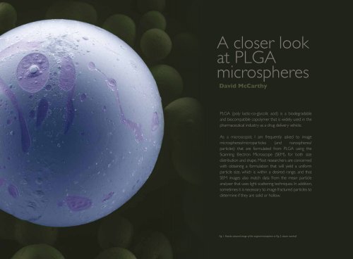
Fig. 1. Pseudo coloured image of the original microsphere in Fig. 2. shown overleaf.<br />
18 Issue 17 MARCH 2010 19
Fig. 2. <strong>PLGA</strong> Microsphere, this is imaged unco<strong>at</strong>ed, low KV, low vacuum and short working distance. The final image capture was 2048 x 1768<br />
resolution with a 30 ms dwell time.<br />
Fig. 3. <strong>PLGA</strong> Microsphere, high magnific<strong>at</strong>ion image of the surface of a smaller sphere, good resolution as the sample is unco<strong>at</strong>ed and taken<br />
under with a low KV, low vacuum, but a short working distance. However, some depth of field is lost.<br />
Samples of <strong>PLGA</strong> <strong>microspheres</strong> are usually dried<br />
for SEM imaging. Freeze drying or spray drying are<br />
the most common methods, the samples are then<br />
routinely gold co<strong>at</strong>ed (Sputter Co<strong>at</strong>ing) prior to<br />
viewing. After co<strong>at</strong>ing, surface charge is sometimes<br />
experienced even <strong>at</strong> low acceler<strong>at</strong>ing voltages due<br />
to the n<strong>at</strong>ure of the m<strong>at</strong>erial. Some formul<strong>at</strong>ions are<br />
thermally sensitive to the beam and also clumping<br />
of particles is common; these clumps will break up<br />
under the beam and thus the surface conduction<br />
from the co<strong>at</strong>ing is broken, resulting in movement<br />
of particles and further charging (I suspect this is<br />
not unique to <strong>PLGA</strong> <strong>microspheres</strong>). This can be<br />
overcome with p<strong>at</strong>ience, or another cycle in the<br />
sputter co<strong>at</strong>er. However, too much gold co<strong>at</strong>ing can<br />
mask any surface ultra structure and render the<br />
spheres clean and smooth. To address these issues,<br />
I have shown a comparison between unco<strong>at</strong>ed, low<br />
vacuum imaging (Figure 2), with routine SEM imaging<br />
(Figure 5) as well as stereo (Figure 6) and pseudo<br />
colouring (Figure 1) on the same microsphere.<br />
Too much gold co<strong>at</strong>ing can<br />
mask any surface ultra<br />
structure and render the<br />
spheres clean and smooth.<br />
Low Vacuum/unco<strong>at</strong>ed SEM<br />
imaging (Large Field Detector)<br />
<strong>PLGA</strong> <strong>microspheres</strong> were <strong>at</strong>tached to a SEM stub<br />
with a carbon adhesive disc and transferred using<br />
a squirrel hair brush. Excess sample was removed<br />
with a gentle spray of compressed air and then<br />
placed into the FEI Quanta FEG 200 for imaging.<br />
To enhance surface morphology of the spheres, a<br />
low acceler<strong>at</strong>ing voltage of 2KV seems to be the<br />
optimum for this kind of sample with a chamber<br />
pressure of 180 Pascal’s, see Figure 2. In addition,<br />
to gain maximum resolution <strong>at</strong> this low KV, the<br />
sample working distance was raised to 4 mm. The<br />
final image capture was 2048 x 1768 resolution<br />
with a 30 ms dwell time. Figure 3 is taken <strong>at</strong> a<br />
higher magnific<strong>at</strong>ion of one of the smaller <strong>PLGA</strong><br />
<strong>microspheres</strong> th<strong>at</strong> shows more surface detail. In<br />
Figure 4, a TV r<strong>at</strong>e view of the sample showing<br />
considerable noise, but with inform<strong>at</strong>ion and detail<br />
present, achieved with a very slow scan and long<br />
dwell time.<br />
SEM imaging <strong>at</strong> High Vacuum<br />
(EHT detector)<br />
The stub containing the <strong>PLGA</strong> <strong>microspheres</strong> was<br />
then taken out of the microscope, transferred to<br />
the sputter co<strong>at</strong>er, an Emitech K550 and co<strong>at</strong>ed<br />
with Gold/Palladium for one minute <strong>at</strong> 20mA, then<br />
20 Issue 17 MARCH 2010 21
as well as masking any surface detail with metal.<br />
The short working distance necessary to achieve<br />
optimum resolution does limit the ability to tilt<br />
specimens but, in Figure 6, a working distance of 10<br />
mm was used to perform a stereo image, with no<br />
significant loss in image quality (although with some<br />
tweaking). In Figure 7, a high stage tilt of 72 degrees<br />
was applied and some charging occurred under<br />
these conditions so a further 2 minutes of co<strong>at</strong>ing<br />
was performed. Figure 1 shows how much more<br />
impact an image can have by being pseudo-coloured.<br />
Acknowledgments<br />
Thanks to Prof. Oya Alpar and Ms. Sara Haider for<br />
<strong>PLGA</strong> sample (School of Pharmacy), David Beamer<br />
(FEI Company) for low vacuum imaging training and<br />
Stephen Gschmeissner for colouring Figure 1.<br />
The advancement of technology in high resolution, low<br />
vacuum, low KV SEM imaging, coupled with the Large<br />
Field secondary electron Detector on unco<strong>at</strong>ed samples,<br />
is now a reality.<br />
Fig. 5. <strong>PLGA</strong> Microspheres, Gold/Palladium co<strong>at</strong>ed (1 minute <strong>at</strong> 20mA) and imaged in high vacuum <strong>at</strong> low KV, short working distance, okay but<br />
showing some charge.<br />
back to the microscope for imaging. To compare<br />
the image with the previous imaging mode, 2KV<br />
was selected (see Figure 5). This image shows good<br />
morphology but a careful <strong>look</strong> will reveal some<br />
charging. Although this is <strong>at</strong> an acceptable level, it is<br />
always best to minimise or elimin<strong>at</strong>e charging totally.<br />
Fig. 4. <strong>PLGA</strong> Microsphere, imaged unco<strong>at</strong>ed, low KV, low vacuum,<br />
short working distance and using a Rapid Scan to show oper<strong>at</strong>ing<br />
noise levels.<br />
Conclusion<br />
The advancement of technology in high resolution,<br />
low vacuum, low KV SEM imaging, coupled with the<br />
Large Field secondary electron Detector (LFD)<br />
on unco<strong>at</strong>ed samples, is now a reality. No sputter<br />
co<strong>at</strong>ing means, not only are we imaging the true<br />
surface, but any change in surface detail from he<strong>at</strong><br />
gener<strong>at</strong>ed by the co<strong>at</strong>er is completely avoided<br />
Fig. 6. <strong>PLGA</strong> Microspheres, Stereo pair (anaglyphs). Higher KV to compens<strong>at</strong>e the longer working distance of 10 mm (eucentric height). Stereo<br />
Glasses required when viewing this image.<br />
22 Issue 17 MARCH 2010 23
Fig. 7. <strong>PLGA</strong> Microspheres. This sample was imaged in the Low vacuum mode, but has been co<strong>at</strong>ed for 3 minutes. I feel showing some loss of<br />
surface detail. A higher KV was use to compens<strong>at</strong>e the longer working distance and a high stage tilt angle of 72 degrees.<br />
David McCarthy<br />
Experimental Officer, Electron Microscopy Unit, The School of Pharmacy, University of London, UK<br />
david.mccarthy@pharmacy.ac.uk<br />
www.pharmacy.ac.uk/david_mccarthy.html<br />
David set-up the EM unit in The School of Pharmacy in January 1977<br />
and has imaged a wide variety of samples using the TEM, SEM and optical<br />
microscopes, including cell cultures, crystals and most forms of drug<br />
delivery vehicles, from liposome’s and polymers to carbon nanotubes. The<br />
unit currently has a FEI CM120 Biotwin TEM with an AMT digital camera,<br />
a FEI Quanta FEG ESEM and a Nikon Microphot optical microscope.<br />
David has been a microscopist for 37 years and has won many awards<br />
for images, including 10 ‘Images of Excellence’ from the Wellcome<br />
Trust (2007/8/9), First prize for the UK Micro and Nanotechnology<br />
Network Image Competition (2006), Overall winner in the ’Visions of<br />
Science’ competition in both 2004 and 2005 and 5 prizes from the RMS<br />
Intern<strong>at</strong>ional Micrograph Competition (including two Firsts). David is also<br />
honorary secretary of the <strong>Society</strong> of Electron Microscope Technology<br />
(SEMT) from 2000 and since 2005 sits on the RMS EM section committee.<br />
24 Issue 17 MARCH 2010


