Download - R&M Materials Handling equipment
Download - R&M Materials Handling equipment
Download - R&M Materials Handling equipment

Create successful ePaper yourself
Turn your PDF publications into a flip-book with our unique Google optimized e-Paper software.
R&M <strong>Materials</strong> <strong>Handling</strong>, Inc.<br />
4501 Gateway Boulevard<br />
Springfield, Ohio 45502<br />
P.: (937) 328-5100<br />
FAX: (937) 325-5319<br />
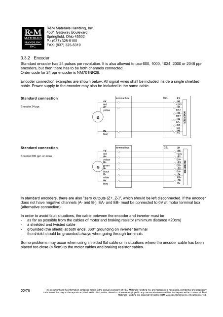
3.3.2 Encoder<br />
Standard encoder has 24 pulses per revolution. It is also allowed to use 600, 1000, 1024, 2000 or 2048 ppr<br />
encoders, but then there has to be both channels connected.<br />
Order code for 24 ppr encoder is NM701NR28.<br />
Encoder connection examples are shown below. All signal wires shall be included inside a single shielded<br />
cable. Power supply to the encoder may also be included in the same cable.<br />
Standard connection<br />
Encoder 24 ppr.<br />
G<br />
+V<br />
red<br />
A+<br />
yellow<br />
0V<br />
blue<br />
terminal box D2L X1<br />
:55<br />
+24V<br />
:51<br />
EA+<br />
:53<br />
EB+<br />
:52<br />
EA-<br />
:54<br />
EB-<br />
:56<br />
0V<br />
INVERTER<br />
Standard connection<br />
Encoder 600 ppr. or more<br />
G<br />
+V<br />
red<br />
A+<br />
yellow<br />
B+<br />
green<br />
A-<br />
black<br />
B-<br />
white<br />
0V<br />
blue<br />
terminal box D2L X1<br />
:55<br />
+24V<br />
:51<br />
EA+<br />
:53<br />
EB+<br />
:52<br />
EA-<br />
:54<br />
EB-<br />
:56<br />
0V<br />
INVERTER<br />
In standard encoders, there are also "zero outputs (Z+, Z-)", which should be left disconnected. If the encoder<br />
does not have negative channels (A- and B-), EA- and EB- must be connected to 0V at motor terminal box<br />
(alternative connection).<br />
In order to avoid fault situations, the cable between the encoder and inverter must be<br />
- as far as possible from the cables of motor and braking resistor (minimum distance >20cm)<br />
- a shielded and twisted cable<br />
- grounded (the shield) at both ends, 360° grounding on inverter terminal<br />
- the shield should be grounded always when going through terminals<br />
Some problems may occur when using shielded flat cable or in situations where the encoder cable has been<br />
placed too close (< 5cm) to the motor cables and braking resistor cables.<br />
22/79<br />
This document and the information contained herein, is the exclusive property of R&M <strong>Materials</strong> <strong>Handling</strong> Inc. and represents a non-public, confidential and proprietary<br />
trade secret that may not be reproduced, disclosed to third parties, altered or otherwise employed in any manner whatsoever without the express written consent of R&M<br />
<strong>Materials</strong> <strong>Handling</strong> Inc. Copyright © (2005) R&M <strong>Materials</strong> <strong>Handling</strong> Inc. All rights reserved.