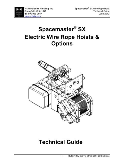
Spacemaster SX Electric Wire Rope Hoists & Options Technical Guide
Spacemaster SX Electric Wire Rope Hoists & Options Technical Guide
Spacemaster SX Electric Wire Rope Hoists & Options Technical Guide

Create successful ePaper yourself
Turn your PDF publications into a flip-book with our unique Google optimized e-Paper software.
R&M Materials Handling, Inc <strong>Spacemaster</strong> ® <strong>SX</strong> <strong>Wire</strong> <strong>Rope</strong> Hoist<br />
Springfield, Ohio USA<br />
<strong>Technical</strong> <strong>Guide</strong><br />
: 800 955-9967 June 2012<br />
www.rmhoist.com<br />
®<br />
<strong>Spacemaster</strong> ® <strong>SX</strong><br />
<strong>Electric</strong> <strong>Wire</strong> <strong>Rope</strong> <strong>Hoists</strong> &<br />
<strong>Options</strong><br />
<strong>Technical</strong> <strong>Guide</strong><br />
1 Bulletin: RM-<strong>SX</strong>-TG-SPEC-2001-22-ENG.doc
®<br />
R&M Materials Handling, Inc <strong>Spacemaster</strong> ® <strong>SX</strong> <strong>Wire</strong> <strong>Rope</strong> Hoist<br />
Springfield, Ohio USA<br />
<strong>Technical</strong> <strong>Guide</strong><br />
: 800 955-9967 June 2012<br />
www.rmhoist.com<br />
Table of Contents<br />
1 PERFORMANCE ................................................................................................................... 7<br />
1.1 General .............................................................................................................................................................. 7<br />
2 HOIST DUTY SERVICE CLASSIFICATION .......................................................................... 7<br />
2.1 FEM Hoist Duty Service Classification ............................................................................................................... 7<br />
2.2 ASME Hoist Duty Service Classification............................................................................................................. 8<br />
2.3 Comparison of Hoist Duty Service Classifications .............................................................................................. 8<br />
3 HOIST FEATURES ................................................................................................................ 9<br />
3.1 Standard Features ............................................................................................................................................. 9<br />
4 HOIST CHARACTERISTICS ............................................................................................... 10<br />
4.1 Height of Lift and Drum Code ........................................................................................................................... 10<br />
4.2 Hoist Speed Accuracy ...................................................................................................................................... 10<br />
4.3 Suspension Type Code .................................................................................................................................... 10<br />
4.4 Reeving Code .................................................................................................................................................. 10<br />
4.5 <strong>Rope</strong> Type Code .............................................................................................................................................. 10<br />
4.6 Hoist Duty Rating ............................................................................................................................................. 10<br />
4.7 Hoist Characteristics Table with P-motor and T-motor ..................................................................................... 11<br />
4.8 Hoist Characteristics Table with S-motor and A-motor ..................................................................................... 21<br />
5 MAIN COMPONENTS - HOIST ........................................................................................... 31<br />
6 HOIST MOTOR .................................................................................................................... 31<br />
6.1 Hoist Motor Features ........................................................................................................................................ 31<br />
6.2 Optional Hoist Motor Features ......................................................................................................................... 31<br />
6.3 Ambient Conditions .......................................................................................................................................... 32<br />
6.4 P-Motors ........................................................................................................................................................... 32<br />
6.5 T-Motors ........................................................................................................................................................... 32<br />
6.6 A-Motors ........................................................................................................................................................... 32<br />
6.7 S-Motors ........................................................................................................................................................... 32<br />
6.8 Motor Temperature Protection ......................................................................................................................... 32<br />
6.9 Motor Cooling ................................................................................................................................................... 32<br />
6.10 Hoist Motor Brake ............................................................................................................................................ 32<br />
6.11 P- Motor Data – Two-speed, 50 Hertz, 3000/500 RPM .................................................................................... 33<br />
6.12 P- Motor Currents – Two-speed, 50 Hertz, 3000/500 RPM .............................................................................. 35<br />
6.13 R- Motor Data – Two-speed, 50 Hertz, 1500/500 RPM .................................................................................... 37<br />
6.14 R- Motor Currents – Two-speed, 50 Hertz, 1500/500 RPM .............................................................................. 38<br />
6.15 P- Motor Data – Two-speed, 60 Hertz, 3600/600 RPM .................................................................................... 39<br />
6.16 P- Motor Currents –Two-speed, 60 Hertz, 3600/600 RPM ............................................................................... 41<br />
6.17 R- Motor Data – Two-speed, 60 Hertz, 1800/600 RPM .................................................................................... 43<br />
6.18 R- Motor Currents –Two-speed, 60 Hertz, 1800/600 RPM............................................................................... 44<br />
6.19 A- Motor Data – Inverter-duty Motor (50 & 60 Hertz) ....................................................................................... 45<br />
6.20 A- Motor Currents – Inverter-duty Motor (50 & 60 Hertz) ................................................................................. 45<br />
6.21 T- Motor Data – Inverter-duty, 100 Hertz, 3000 RPM ....................................................................................... 46<br />
6.22 T- Motor Data – Inverter-duty, 120 Hertz, 3600 RPM ....................................................................................... 47<br />
6.23 T- Motor Currents – Inverter-duty Motor (100 & 120 Hertz) .............................................................................. 48<br />
6.24 S- Motor Data – Inverter-duty, ESR, 100 Hertz ................................................................................................ 49<br />
6.25 S- Motor Data – Inverter-duty, ESR, 120 Hertz ................................................................................................ 50<br />
6.26 S- Motor Currents – Inverter-duty Motor, ESR, (100 & 120 Hertz) ................................................................... 51<br />
7 HOIST GEARBOX ............................................................................................................... 52<br />
7.1 Hoist Gear Reducer ......................................................................................................................................... 52<br />
7.2 Hoist Gear Lubricant ........................................................................................................................................ 52<br />
8 ROPE DRUM ....................................................................................................................... 53<br />
8.1 Drum Data ........................................................................................................................................................ 53<br />
8.2 Drum Length Code ........................................................................................................................................... 53<br />
8.3 <strong>Rope</strong> Clamps ................................................................................................................................................... 54<br />
2 RM-<strong>SX</strong>-TG-SPEC-2001-22-ENG.doc
®<br />
R&M Materials Handling, Inc <strong>Spacemaster</strong> ® <strong>SX</strong> <strong>Wire</strong> <strong>Rope</strong> Hoist<br />
Springfield, Ohio USA<br />
<strong>Technical</strong> <strong>Guide</strong><br />
: 800 955-9967 June 2012<br />
www.rmhoist.com<br />
8.4 <strong>Rope</strong> <strong>Guide</strong> ...................................................................................................................................................... 54<br />
9 REEVING ILLUSTRATION .................................................................................................. 56<br />
9.1 Single Reeved – <strong>SX</strong>2, <strong>SX</strong>3, <strong>SX</strong>4, and <strong>SX</strong>5 ...................................................................................................... 56<br />
9.2 Double Reeved – Old Style by Special Request .............................................................................................. 56<br />
9.3 Double Reeved – <strong>SX</strong>5, <strong>SX</strong>6 and <strong>SX</strong>7 <strong>Hoists</strong> ................................................................................................... 57<br />
9.4 <strong>Rope</strong> Anchor .................................................................................................................................................... 57<br />
10 WIRE ROPE ......................................................................................................................... 58<br />
10.1 <strong>Wire</strong> <strong>Rope</strong> <strong>Technical</strong> Data ............................................................................................................................... 58<br />
10.2 Heavy Duty <strong>Wire</strong> <strong>Rope</strong> – RR09 ........................................................................................................................ 59<br />
11 BOTTOM BLOCK ................................................................................................................ 60<br />
11.1 Bottom Block Dimensions – <strong>SX</strong>2, <strong>SX</strong>3, <strong>SX</strong>4 <strong>Hoists</strong> ......................................................................................... 60<br />
11.2 Bottom Block Dimensions – <strong>SX</strong>5, <strong>SX</strong>6, <strong>SX</strong>7 <strong>Hoists</strong> ......................................................................................... 61<br />
11.3 Block Construction ........................................................................................................................................... 62<br />
11.4 RSN and HBC Hook Forging Dimensions ........................................................................................................ 63<br />
11.5 DIN Hooks – HOK09 ........................................................................................................................................ 63<br />
11.6 Other Hooks – HOK07 ..................................................................................................................................... 64<br />
11.7 Ramshorn (twin-points) Hooks – HOK03 ......................................................................................................... 64<br />
11.8 Sheaves ........................................................................................................................................................... 64<br />
12 HOIST LIMIT SWITCH - STANDARD .................................................................................. 65<br />
12.1 <strong>SX</strong>2-<strong>SX</strong>7 <strong>Hoists</strong> ............................................................................................................................................... 65<br />
13 OVERLOAD DEVICE, MECHANICAL (MEC) ..................................................................... 66<br />
14 TROLLEY ............................................................................................................................. 67<br />
14.1 Low Headroom Hoist ........................................................................................................................................ 67<br />
14.2 Normal Headroom Hoist ................................................................................................................................... 68<br />
14.3 Patented Track Wheel Option – TR26 ............................................................................................................. 68<br />
14.4 Swivel Trolley for Curved Track ....................................................................................................................... 69<br />
14.5 Double Girder Trolley ....................................................................................................................................... 70<br />
14.6 Trolley Gauge ................................................................................................................................................... 70<br />
14.7 Cross Mounting Double Girder Hoist ................................................................................................................ 70<br />
15 INVERTER CONTROL......................................................................................................... 71<br />
15.1 Speed Control Types ....................................................................................................................................... 71<br />
15.2 Dynamic Braking .............................................................................................................................................. 71<br />
15.3 Factory settings of Inverters ............................................................................................................................. 71<br />
15.4 Open Loop and Closed Loop Systems ............................................................................................................. 72<br />
16 VARIABLE FREQUENCY DRIVE TYPES ........................................................................... 73<br />
16.1 ControlMaster TM CMXC .................................................................................................................................... 73<br />
16.2 ControlMaster TM NXT ....................................................................................................................................... 74<br />
16.3 ControlMaster TM Select VFD ............................................................................................................................ 75<br />
16.4 ControlMaster TM Plus VFD + T-motor ............................................................................................................... 76<br />
16.5 ControlMaster TM Elite VFD <strong>Technical</strong> Data ...................................................................................................... 77<br />
16.6 ControlMaster TM Elite VFD + T-motor ............................................................................................................... 78<br />
16.7 ControlMaster TM Elite VFD + S-motor = ESR ................................................................................................... 78<br />
16.8 ControlMaster TM Elite VFD + A-motor = ASR ................................................................................................... 79<br />
17 INVERTER TROLLEY SPEEDS .......................................................................................... 80<br />
17.1 Low Headroom - Inverter Trolley ...................................................................................................................... 80<br />
17.2 Normal Headroom – Inverter Trolley ................................................................................................................ 80<br />
17.3 Double Girder - Inverter Trolley ........................................................................................................................ 81<br />
18 TWO-SPEED TROLLEY SPEEDS ...................................................................................... 81<br />
18.1 Low Headroom – Two-speed Trolley ............................................................................................................... 81<br />
18.2 Normal Headroom – Two-speed Trolley........................................................................................................... 82<br />
18.3 Double Girder – Two-speed Trolley ................................................................................................................. 82<br />
19 GEK DRIVE .......................................................................................................................... 83<br />
19.1 MF06 Inverter-duty Motor ................................................................................................................................. 83<br />
3 RM-<strong>SX</strong>-TG-SPEC-2001-22-ENG.doc
®<br />
R&M Materials Handling, Inc <strong>Spacemaster</strong> ® <strong>SX</strong> <strong>Wire</strong> <strong>Rope</strong> Hoist<br />
Springfield, Ohio USA<br />
<strong>Technical</strong> <strong>Guide</strong><br />
: 800 955-9967 June 2012<br />
www.rmhoist.com<br />
19.2 MF06 Two-speed Motor ................................................................................................................................... 83<br />
20 GEK GEAR LUBRICANTS .................................................................................................. 83<br />
21 BRIDGE AND TROLLEY MOTORS & BRAKES ................................................................ 84<br />
21.1 Standard Motor Features ................................................................................................................................. 84<br />
21.2 Motor <strong>Options</strong> ................................................................................................................................................... 84<br />
21.3 Compact Brake ................................................................................................................................................ 84<br />
21.4 D.C. Brake ........................................................................................................................................................ 84<br />
21.5 MF06 Inverter-duty Motor Data ........................................................................................................................ 85<br />
21.6 MF07 Inverter-duty Motor Data ........................................................................................................................ 86<br />
21.7 MF06 Two-speed Motor Data ........................................................................................................................... 86<br />
21.8 MF07 Two-speed Motor Data ........................................................................................................................... 87<br />
21.9 MF10 Two-speed Motor Data ........................................................................................................................... 87<br />
22 HOIST CONTROLS ............................................................................................................. 88<br />
22.1 Monorail Hoist (Solo Hoist) ............................................................................................................................... 88<br />
22.2 Crane Package Hoist ....................................................................................................................................... 88<br />
22.3 Power Supply and Control Voltage .................................................................................................................. 88<br />
23 HOIST PROTECTION RATING ........................................................................................... 88<br />
24 PENDANT ............................................................................................................................ 89<br />
24.1 <strong>Technical</strong> Data ................................................................................................................................................. 89<br />
24.2 Direction Symbols or Labels ............................................................................................................................. 89<br />
25 HOISTMONITOR ® ................................................................................................................ 90<br />
25.1 HoistMonitor ® – HS11 ...................................................................................................................................... 90<br />
25.2 Optional Features ............................................................................................................................................. 91<br />
25.3 Calibration ........................................................................................................................................................ 91<br />
25.4 HoistMonitor ® Select – HS12 ........................................................................................................................... 91<br />
25.5 HoistMonitor ® Elite – HS13 .............................................................................................................................. 92<br />
26 OUTDOORS SERVICE & OTHER ENVIRONMENTS ......................................................... 93<br />
26.1 Environment Categories ................................................................................................................................... 93<br />
26.2 Protection Feature Summary ........................................................................................................................... 94<br />
27 SURFACE TREATMENT ..................................................................................................... 95<br />
27.1 Hoist & Trolley Color Layout ............................................................................................................................. 95<br />
27.2 End Truck Paint Specification .......................................................................................................................... 95<br />
27.3 Standard Painting Method for Hoist ................................................................................................................. 96<br />
27.4 Special Painting Specification for Hoist ............................................................................................................ 96<br />
28 MATERIALS ........................................................................................................................ 97<br />
29 HOIST OPTIONS ............................................................................................................... 100<br />
29.1 Second Hoist Brake – BRA01 ........................................................................................................................ 100<br />
29.2 Manual Brake Release for Trolley Motor – BRA05 ......................................................................................... 100<br />
29.3 Manual Brake Release for Hoist Motor – BRA07 ........................................................................................... 100<br />
29.4 Trolley, Double Girder High Connection – DES01 ......................................................................................... 100<br />
29.5 Trolley, Double Girder Low Connection – DES01 .......................................................................................... 100<br />
29.6 Control Transformer & Mainline Contactor – DES02 ...................................................................................... 100<br />
29.7 Bumper Extensions between Trolleys – DES29 ............................................................................................. 100<br />
29.8 Trolley, Special Flange Width for Low Headroom – DIM19 ............................................................................ 100<br />
29.9 Trolley, Special Flange Width for Normal Headroom – DIM20 ....................................................................... 100<br />
29.10 <strong>Electric</strong> Provision – EL05 ............................................................................................................................... 101<br />
29.11 Special Encoder on Hoist – EL20 ................................................................................................................... 101<br />
29.12 Hoist Inverter Control Method – EL36 ............................................................................................................ 101<br />
29.13 Hoist without <strong>Electric</strong>al Controls – ELE65 ...................................................................................................... 101<br />
29.14 Transformer for Trolley Control – ELE68........................................................................................................ 101<br />
29.15 Bottom Side Drum Cover – GE24 .................................................................................................................. 101<br />
29.16 Hoist Motor, IP66 Protection – HM04 ............................................................................................................. 101<br />
29.17 Hoist Motor, Thermal Protection – HM05 ....................................................................................................... 101<br />
29.18 Hoist Motor, Class H Insulation – HM12......................................................................................................... 102<br />
4 RM-<strong>SX</strong>-TG-SPEC-2001-22-ENG.doc
®<br />
R&M Materials Handling, Inc <strong>Spacemaster</strong> ® <strong>SX</strong> <strong>Wire</strong> <strong>Rope</strong> Hoist<br />
Springfield, Ohio USA<br />
<strong>Technical</strong> <strong>Guide</strong><br />
: 800 955-9967 June 2012<br />
www.rmhoist.com<br />
29.19 Speed Sensor on Hoist Motor – HM13 ........................................................................................................... 102<br />
29.20 Lockable Hook in Bottom Block – HOK02 ...................................................................................................... 102<br />
29.21 Heavy-weighted Bottom Block – HOK11 ........................................................................................................ 102<br />
29.22 Rain/Dust Cover for Hoist – HS04 .................................................................................................................. 102<br />
29.23 Hoist Drum Brake – HS07 .............................................................................................................................. 102<br />
29.24 Slack <strong>Rope</strong> Protection (10% of nominal load) – HS16 ................................................................................... 103<br />
29.25 Limit Switch, Hook Operated – HS22 ............................................................................................................. 103<br />
29.26 Hard Chrome Shaft for <strong>Rope</strong> <strong>Guide</strong> – HS23 .................................................................................................. 103<br />
29.27 Synchro for Hoisting – HS27 .......................................................................................................................... 103<br />
29.28 Load Limiter, Two-step – LIM07 ..................................................................................................................... 103<br />
29.29 Load Limiter, Three-step – LIM08 .................................................................................................................. 103<br />
29.30 Limit Switch, Trolley Traveling Two-step (Slowdown + Stop) - LIM15 ............................................................ 103<br />
29.31 Limit Switch, Extra - Level Setting – LIM16 .................................................................................................... 104<br />
29.32 Limit Switch, Hoist Operating with Bypass – LIM17 ....................................................................................... 105<br />
29.33 Limit Switch, Special Rotating – LIM19 .......................................................................................................... 106<br />
29.34 Overload Indication, Light and Horn Combination – LOA05 ........................................................................... 106<br />
29.35 Overload Indication, Red Light – LOA07 ........................................................................................................ 106<br />
29.36 Lug Mount Suspension................................................................................................................................... 106<br />
29.37 Nonstandard Voltage/frequency for Hoist....................................................................................................... 106<br />
29.38 Standby Heater for Motors – MOT03 (hoist) MOT04 (trolley)......................................................................... 106<br />
29.39 Hoist Motor External Fan – MOT08 ................................................................................................................ 107<br />
29.40 Rain/Dust Cover for Trolley Motor – MOT10 .................................................................................................. 107<br />
29.41 Anti-jump Catches for Double Girder Trolleys – OTH23................................................................................. 107<br />
29.42 Rail Sweeps – OTH61 .................................................................................................................................... 107<br />
29.43 Special Paint Thickness – PAI03 ................................................................................................................... 107<br />
29.44 Special Paint for Offshore Environment – PAI06 ............................................................................................ 107<br />
29.45 IP-type of Hoist Panel (Add for IP66) – PAN01 .............................................................................................. 107<br />
29.46 Standby Heater for Hoist Control Panel – PAN02 .......................................................................................... 107<br />
29.47 Stainless Steel Hoist Panel (IP55) – PAN03 .................................................................................................. 107<br />
29.48 Contactor Control, Trolley – Two-speed – PRI02 ........................................................................................... 108<br />
29.49 Trolley Rail Gauge, One Step Wider from Standard – PRI06 ......................................................................... 108<br />
29.50 Trolley Rail Gauge, One Step Smaller from Standard – PRI07 ...................................................................... 108<br />
29.51 Enclosure Mounting of Radio Receiver – REM18 .......................................................................................... 108<br />
29.52 Stainless <strong>Wire</strong> <strong>Rope</strong> – RR08 .......................................................................................................................... 108<br />
29.53 Heavy Duty <strong>Wire</strong> <strong>Rope</strong> – RR09 ...................................................................................................................... 108<br />
29.54 Trolley Speed, Faster than Standard – SPD10 .............................................................................................. 108<br />
29.55 Trolley Speed, Slower than Standard – SPD11 ............................................................................................. 108<br />
29.56 Trolley Motor, IP66 Protection – TM04 ........................................................................................................... 108<br />
29.57 Trolley Motor, Thermal Protection – TM05 ..................................................................................................... 108<br />
29.58 Trolley Motor, Class H Insulation – TM12 ...................................................................................................... 108<br />
29.59 Anti-collision Device for Trolley – TR16 ......................................................................................................... 109<br />
30 HOIST SPEEDS ................................................................................................................. 109<br />
31 QX ® CRANE PACKAGE .................................................................................................... 109<br />
32 CRANE FESTOON SYSTEM ............................................................................................. 110<br />
32.1 Support Rail Mounting .................................................................................................................................... 110<br />
32.2 Indoor Location .............................................................................................................................................. 110<br />
32.3 Outdoor Location ............................................................................................................................................ 110<br />
33 NRGMASTER ELECTRIFICATION SYSTEM ................................................................... 111<br />
33.1 Cables ............................................................................................................................................................ 111<br />
33.2 Controller ........................................................................................................................................................ 111<br />
33.3 Bridge Girder Selection .................................................................................................................................. 111<br />
33.4 Hoist Speeds and Controls ............................................................................................................................. 112<br />
33.5 NRGmaster - Crane Specification and Additional Features ........................................................................... 112<br />
33.6 NRGmaster Specification ............................................................................................................................... 113<br />
33.7 Two Similar <strong>Hoists</strong> Arrangement .................................................................................................................... 113<br />
5 RM-<strong>SX</strong>-TG-SPEC-2001-22-ENG.doc
®<br />
R&M Materials Handling, Inc <strong>Spacemaster</strong> ® <strong>SX</strong> <strong>Wire</strong> <strong>Rope</strong> Hoist<br />
Springfield, Ohio USA<br />
<strong>Technical</strong> <strong>Guide</strong><br />
: 800 955-9967 June 2012<br />
www.rmhoist.com<br />
34 BRIDGE PANEL ................................................................................................................ 114<br />
35 BRIDGE PANEL DIMENSIONS......................................................................................... 114<br />
36 PLUG RULES .................................................................................................................... 115<br />
36.1 Control Cables ............................................................................................................................................... 115<br />
36.2 Power Cables ................................................................................................................................................. 115<br />
36.3 Plug Kits and Stainless Steel Enclosures ....................................................................................................... 116<br />
37 BRIDGE GIRDER............................................................................................................... 116<br />
38 TANDEM HOISTS .............................................................................................................. 116<br />
39 CRANE OPTIONS ............................................................................................................. 117<br />
39.1 Thermal Protection for Bridge Motor – BM08 ................................................................................................. 117<br />
39.2 Bridge Motor, IP66 Protection – BM09 ........................................................................................................... 117<br />
39.3 Bridge Motor, Class H Insulation – BM11....................................................................................................... 117<br />
39.4 Manual Brake Release for Bridge Motor – BRA06 ......................................................................................... 117<br />
39.5 Anti-collision Device for Second Crane – BT20 .............................................................................................. 117<br />
39.6 Rubber Cables for Hoist Power Supply – CBL07 ........................................................................................... 117<br />
39.7 Bumper Extensions between End Trucks – DES44 ....................................................................................... 117<br />
39.8 Insulation for Bridge Panel – EL23 ................................................................................................................. 117<br />
39.9 Thermostat Controlled Heating – EL24 .......................................................................................................... 117<br />
39.10 Bridge Panel Lights – EL25 ............................................................................................................................ 117<br />
39.11 Rain Cover for Bridge Panel – EL26 .............................................................................................................. 117<br />
39.12 Cooling Device for Bridge Panel – EL29 ........................................................................................................ 118<br />
39.13 Indicator Beacon for Crane – EL52 ................................................................................................................ 118<br />
39.14 Horn – ELE05 ................................................................................................................................................. 118<br />
39.15 All <strong>Electric</strong>s in Bridge Panel – ELE10 ............................................................................................................. 118<br />
39.16 Flashing Light for Traveling – ELE20 (replaced by ELE98) ............................................................................ 118<br />
39.17 Pliotex Type <strong>Wire</strong> Marking – ELE48 ............................................................................................................... 118<br />
39.18 Crane Lights (Provision only) – ELE61 .......................................................................................................... 118<br />
39.19 Limit Switch, Hook-Operated, Trips Mainline Contactor – ELE64 .................................................................. 118<br />
39.20 Transformer for Entire Crane – ELE67 ........................................................................................................... 119<br />
39.21 Transformer for Bridge Control – ELE69 ........................................................................................................ 119<br />
39.22 Warning Indication for Traveling Movement – ELE98 .................................................................................... 119<br />
39.23 Special Lubrication for Gears – GE21 ............................................................................................................ 119<br />
39.24 Load Display – HS09 ..................................................................................................................................... 119<br />
39.25 Load Display for Total or Individual Load – HS28 .......................................................................................... 119<br />
39.26 Limit Switch, Bridge Traveling Two-step (Slowdown + Stop) – LIM12 ........................................................... 119<br />
39.27 Nonstandard Voltage/frequency for Crane ..................................................................................................... 119<br />
39.28 Standby Heater for Bridge Motor – MOT17 .................................................................................................... 120<br />
39.29 Rain/Dust Cover for Bridge Motor – MOT18 .................................................................................................. 120<br />
39.30 Anti-collision Device for Crane – OTH08 ........................................................................................................ 120<br />
39.31 Rail Sweeps – OTH21 .................................................................................................................................... 121<br />
39.32 Storm Locks – OTH22 .................................................................................................................................... 121<br />
39.33 Anti-jump Catches for Crane – OTH24 .......................................................................................................... 121<br />
39.34 Stainless Steel Bridge Panel (IP55) – PAN04 ................................................................................................ 122<br />
39.35 IP-type of Bridge Panel (Add for IP66) – PAN07 ............................................................................................ 122<br />
39.36 Standby Heater for Bridge Control Panel – PAN08 ........................................................................................ 122<br />
39.37 Plug Source in Bridge Panel – PAN17 ........................................................................................................... 122<br />
39.38 Standby Heater for Pendant Enclosure – PEN03 ........................................................................................... 122<br />
39.39 Contactor Control, Bridge – PRI01 ................................................................................................................. 122<br />
39.40 Display in Radio Transmitter – REM20 .......................................................................................................... 122<br />
39.41 Longer Chain for Trolley Tow Arm & Festoon – PS05 ................................................................................... 122<br />
39.42 Crane Sticker Set – ST09 ............................................................................................................................... 122<br />
39.43 Sticker Set – ST11 ......................................................................................................................................... 122<br />
39.44 ControlMaster TM Anti-Sway System – DP01 .................................................................................................. 123<br />
40 CONVERSIONS ................................................................................................................. 123<br />
6 RM-<strong>SX</strong>-TG-SPEC-2001-22-ENG.doc
®<br />
R&M Materials Handling, Inc <strong>Spacemaster</strong> ® <strong>SX</strong> <strong>Wire</strong> <strong>Rope</strong> Hoist<br />
Springfield, Ohio USA<br />
<strong>Technical</strong> <strong>Guide</strong><br />
: 800 955-9967 June 2012<br />
www.rmhoist.com<br />
1 Performance<br />
1.1 General<br />
<strong>Hoists</strong> are designed for lifting and transporting of materials only. Under no conditions or circumstances<br />
are hoists to be used for lifting or transporting of personnel.<br />
<strong>Spacemaster</strong> ® <strong>SX</strong> wire rope hoists are designed for indoor use where the ambient temperature can be<br />
between 14°F [-10°C] and 104°F [40°C], the elevation is less than 3300 ft [1000m], and the relative<br />
humidity is less than 90%.<br />
When specially equipped, the hoists may be used for outdoor use, in more extreme ambient conditions,<br />
or at a higher elevation. See the Outdoors Service & Other Environments section for the categories<br />
and the special protection features.<br />
The sound intensity level of the hoist in the assumed operating location does not exceed 70dB.<br />
2 Hoist Duty Service Classification<br />
2.1 FEM Hoist Duty Service Classification<br />
Service conditions have important influence on the performance of wearing parts of a hoist such as gears,<br />
bearings, rope, sheaves, electrical equipment, brake linings, load and lift limit devices, and wheels, etc.<br />
Careful consideration of the hoist-duty service classifications will enable the user to evaluate the<br />
application, and to obtain a hoist designed for optimum performance and minimum maintenance.<br />
According to FEM9.511 standard, the hoist-duty service classification can be determined from its 1) load<br />
spectrum 2) average daily operating time.<br />
2.1.1 FEM Load Spectrum<br />
The load spectrum can be determined from the table below.<br />
LIGHT<br />
Occasional full loads.<br />
Usually light load.<br />
Small fixed load.<br />
MEDIUM<br />
Occasional full loads.<br />
Usually light load.<br />
Average fixed load.<br />
Load %<br />
Load %<br />
Operating time %<br />
Operating time %<br />
HEAVY<br />
Repetitive full loads.<br />
Usually average load.<br />
Heavy fixed load.<br />
VERY HEAVY<br />
Usually almost full loads.<br />
Very heavy fixed load.<br />
Load %<br />
Operating time %<br />
Load %<br />
Operating time %<br />
7 RM-<strong>SX</strong>-TG-SPEC-2001-22-ENG.doc
®<br />
R&M Materials Handling, Inc <strong>Spacemaster</strong> ® <strong>SX</strong> <strong>Wire</strong> <strong>Rope</strong> Hoist<br />
Springfield, Ohio USA<br />
<strong>Technical</strong> <strong>Guide</strong><br />
: 800 955-9967 June 2012<br />
www.rmhoist.com<br />
2.1.2 FEM Average Daily Operating Time<br />
The average daily operating time of the hoist can be calculated from the running time of the hoisting<br />
machinery [hours/day].<br />
2∗<br />
H ∗ N ∗T<br />
t =<br />
V ∗60<br />
♦ H = average hoisting height [m]<br />
♦ N = number of work cycles per hour [cycles/h]<br />
♦ T = daily working time [h]<br />
♦ V = hoisting speed [m/min]<br />
2.1.3 Determining the FEM hoist duty service classification<br />
When the load spectrum and the average daily operating time of the hoist are identified, the duty service<br />
classification of the hoist is obtained from the table below.<br />
Load spectrum<br />
LIGHT<br />
MEDIUM<br />
HEAVY<br />
VERY HEAVY<br />
Average daily operating time<br />
ISO/FEM<br />
(hours per day)<br />
≤ 0.5 ≤ 1 ≤ 2 ≤ 4 ≤ 8 ≤ 16<br />
M3<br />
1Bm<br />
M4<br />
1Am<br />
M3<br />
1Bm<br />
M4<br />
1Am<br />
M5<br />
2m<br />
M3<br />
1Bm<br />
M4<br />
1Am<br />
M5<br />
2m<br />
M6<br />
3m<br />
M4<br />
1Am<br />
M5<br />
2m<br />
M6<br />
3m<br />
M7<br />
4m<br />
M5<br />
2m<br />
M6<br />
3m<br />
M7<br />
4m<br />
M6<br />
3m<br />
M7<br />
4m<br />
2.2 ASME Hoist Duty Service Classification<br />
For information about ASME Hoist Duty Service Classification, reference ASME publication catalog<br />
ASME HST-4 (latest edition) for electric wire rope hoists.<br />
2.3 Comparison of Hoist Duty Service Classifications<br />
Code 3 4 5 6<br />
ISO M3 M4 M5 M6<br />
FEM 1Bm 1Am 2m 3m<br />
ASME HST-4M H2 H3 H4 H4*<br />
Starts per Hour<br />
FEM 150 180 240 300 360<br />
ASME HST-4M 75 150 300 300 ---<br />
FEM Intermittent Duty-ANSI/ASME Uniformly Distributed Work Periods (min/hr)<br />
FEM<br />
ASME HST-4M 7.5 15 30 30 ---<br />
*None of the <strong>Spacemaster</strong> ® <strong>SX</strong> hoists can be rated higher than ASME H4 duty service classification.<br />
8 RM-<strong>SX</strong>-TG-SPEC-2001-22-ENG.doc
®<br />
R&M Materials Handling, Inc <strong>Spacemaster</strong> ® <strong>SX</strong> <strong>Wire</strong> <strong>Rope</strong> Hoist<br />
Springfield, Ohio USA<br />
<strong>Technical</strong> <strong>Guide</strong><br />
: 800 955-9967 June 2012<br />
www.rmhoist.com<br />
3 Hoist Features<br />
3.1 Standard Features<br />
Two-speed hoist motor (6:1 ratio) with thermal protection, class F insulation<br />
D.C. disc hoist brake<br />
Compact hoist gear box<br />
Overload limit device<br />
Over-travel protection<br />
<strong>Rope</strong> guide<br />
**Hoist and trolley controls<br />
Inverter trolley control<br />
65 fpm [20 m/min] trolley speed<br />
Trolley drive with inverter-duty motor with brake<br />
Crown tread wheels on under hung trolley – suitable for flat or tapered flange<br />
Flat tread wheels on double girder trolley<br />
Trolley bumper and safety drop lug<br />
HBC or RSN style hook with spring-return safety latch<br />
IP55 protection rating for motor<br />
Standard hoist nameplate carries a CSA c/us rating and a NEMA 3R rating for electrical<br />
enclosures<br />
Plugs for power and control cables (some exceptions)<br />
Wiring Diagram<br />
Owner’s manual - Paper + CD (1 set)<br />
Manual includes certificates for: Hoist (load) test<br />
RSN or HBC hook<br />
<strong>Wire</strong> rope<br />
** For hoists used on monorails, the mainline contactor and control transformer, and the pushbutton<br />
pendant are not standard equipment and must be added as separate adders for all hoist models.<br />
** For hoists used on cranes, the mainline contactor and control transformer are supplied as standard<br />
equipment in the bridge panel. The pushbutton pendant is added separately to the crane components<br />
package.<br />
9 RM-<strong>SX</strong>-TG-SPEC-2001-22-ENG.doc
®<br />
R&M Materials Handling, Inc <strong>Spacemaster</strong> ® <strong>SX</strong> <strong>Wire</strong> <strong>Rope</strong> Hoist<br />
Springfield, Ohio USA<br />
<strong>Technical</strong> <strong>Guide</strong><br />
: 800 955-9967 June 2012<br />
www.rmhoist.com<br />
4 Hoist Characteristics<br />
The hoist characteristics table is a summary of the hoist characteristics, which include:<br />
Height of lift and corresponding drum (length) code<br />
Hoist speeds including alternate speeds for both two-speed and inverter controls<br />
Availability of standard suspension types for each model<br />
Reeving Code<br />
<strong>Rope</strong> type code for each model<br />
Hoist duty rating<br />
4.1 Height of Lift and Drum Code<br />
The height of lift along with the corresponding drum code is listed for each basic model.<br />
4.2 Hoist Speed Accuracy<br />
The actual hoist speed of hoist units with the same nominal speed but with a different reeving system,<br />
gearing ratio, and motor types could vary ±15%. Better speed accuracy can be attained through VFD<br />
(inverter) controls where the speeds of both hoists can be fine-tuned through the inverter parameters.<br />
Exact matching speeds could be important for hoists that would operate together.<br />
4.3 Suspension Type Code<br />
Suspension types that are available for the hoist model are marked with a code. Special suspensions are<br />
not included here.<br />
Suspension Code in table Description<br />
J<br />
Special low headroom hoist<br />
L<br />
Low headroom hoist<br />
DH<br />
Double girder trolley–high: Height above the rail is higher than the standard trolley<br />
- to get better headroom below the rail.<br />
D0<br />
Double girder trolley–standard<br />
DW Double girder trolley–low: Height above the rail is lower than the standard trolley –<br />
to get better overhead clearance but it increases headroom.<br />
N<br />
Normal headroom hoist<br />
F<br />
Foot mount<br />
4.4 Reeving Code<br />
Reeving code Description Reeving code Description<br />
021 2 part single 022 2 part double<br />
041 4 part single 042 4 part double<br />
061 6 part single 062 6 part double<br />
081 8 part single 082 8 part double<br />
A2 2 part single Smaller rope diameter; reduced capacity; longer lift; <strong>SX</strong>4 low headroom hoists only<br />
A4 4 part single Smaller rope diameter; reduced capacity; longer lift; <strong>SX</strong>4 low headroom hoists only<br />
4.5 <strong>Rope</strong> Type Code<br />
The rope type code is listed for each height of lift. The characteristics of the wire rope can be found in the<br />
<strong>Wire</strong> <strong>Rope</strong> section. The double-reeved hoists use two separate ropes – a right-hand lay and a left-hand<br />
lay. See <strong>Wire</strong> <strong>Rope</strong> section for definition of <strong>Rope</strong> Type code.<br />
4.6 Hoist Duty Rating<br />
ASME hoist duty ratings (H3, H4, etc.) apply to hoists marked with typical U.S. capacities (for example, 1<br />
ton = 2000 lbs = 907 kg) and do not apply to hoists marked with typical metric capacities (for example, 1<br />
metric ton = 1,000 kg = 2,200 lbs). FEM/ISO ratings apply to hoists with typical metric capacities.<br />
10 RM-<strong>SX</strong>-TG-SPEC-2001-22-ENG.doc
®<br />
R&M Materials Handling, Inc <strong>Spacemaster</strong> ® <strong>SX</strong> <strong>Wire</strong> <strong>Rope</strong> Hoist<br />
Springfield, Ohio USA<br />
<strong>Technical</strong> <strong>Guide</strong><br />
: 800 955-9967 June 2012<br />
www.rmhoist.com<br />
4.7 Hoist Characteristics Table with P-motor and T-motor<br />
Load<br />
Duty Rating<br />
Suspension Drum <strong>Rope</strong><br />
Contactor Control Inverter Control<br />
Hoist<br />
Reeving<br />
Ton Kg L D D D N F J<br />
Code<br />
HOL<br />
Code<br />
P-motor<br />
T-motor<br />
Gear Motor Speed- 60 Hz Motor Speed-60 Hz<br />
ASME FEM/ISO H 0 W ft m Type Ratio code fpm m/min code fpm m/min<br />
3/4 800 <strong>SX</strong>2 021 L H 0 N F A 39’-4” 12 A F 134.2 P1 40/6.6 12/2 T1 40 12<br />
H4+ 3m/M6 C 62’-4” 19<br />
1 1000 <strong>SX</strong>2 021 L H 0 N F A 39’-4” 12 A F 134.2 P1 40/6.6 12/2 T1 40 12<br />
H4 2m/M5 C 62’-4” 19<br />
1 ½ 1600 <strong>SX</strong>2 041 L H 0 N F A 19'-8" 6 A F 134.2 P1 20/3.1 6/1 T1 20 6<br />
H4+ 3m/M6 C 31’-2” 9.5<br />
2 2000 <strong>SX</strong>2 041 L H 0 N F A 19'-8" 6 A F 134.2 P1 20/3.1 6/1 T1 20 6<br />
H4 2m/M5 C 31’-2” 9.5<br />
1 1000 <strong>SX</strong>3 021 L H 0 N F A 39’-4” 12 A F 134.2 P2 40/6.6 12/2 T2 40 12<br />
H4+ 3m/M6 C 62’-4” 19 G 106 P2 50/7.8 15/2.5 T2 50 15<br />
H 87.7 P3 60/9.8 19/3.3 T3 60 19<br />
1 ¼ 1250 <strong>SX</strong>3 021 L H 0 N F A 39’-4” 12 A F 134.2 P2 40/6.6 12/2 T2 40 12<br />
H4+ 3m/M6 C 62’-4” 19 G 106 P2 50/7.8 15/2.5 T2 50 15<br />
H 87.7 P3 60/9.8 19/3.3 T3 60 19<br />
1 ½ 1600 <strong>SX</strong>3 021 L H 0 N F A 39’-4” 12 A F 134.2 P2 40/6.6 12/2 T2 40 12<br />
H4 2m/M5 C 62’-4” 19 G 106 P2 50/7.8 15/2.5 T2 50 15<br />
H 87.7 P3 60/9.8 19/3.3 T3 60 19<br />
2 2000 <strong>SX</strong>3 041 L H 0 N F A 19'-8" 6 A F 134.2 P2 20/3.1 6/1 T2 20 6<br />
H4+ 3m/M6 C 31’-2” 9.5 G 106 P2 25/3.9 7.5/1.3 T2 25 7.5<br />
H 87.7 P3 30/4.9 9.5/1.6 T3 30 9.5<br />
2 ½ 2500 <strong>SX</strong>3 041 L H 0 N F A 19'-8" 6 A F 134.2 P2 20/3.1 6/1 T2 20 6<br />
H4+ 3m/M6 C 31’-2” 9.5 G 106 P2 25/3.9 7.5/1.3 T2 25 7.5<br />
H 87.7 P3 30/4.9 9.5/1.6 T3 30 9.5<br />
3 3200 <strong>SX</strong>3 041 L H 0 N F A 19'-8" 6 A F 134.2 P2 20/3.1 6/1 T2 20 6<br />
H4 2m/M5 C 31’-2” 9.5 G 106 P2 25/3.9 7.5/1.3 T2 25 7.5<br />
H 87.7 P3 30/4.9 9.5/1.6 T3 30 9.5<br />
1 1000 <strong>SX</strong>4 A2 L C 73’-9” 22.5 B F 160.3 P2 40/6.6 12/2 T2 40 12<br />
H4+ 3m/M6 D 98’-5” 30 H 104.7 P4 60/9.8 19/3.3 T4 60 19<br />
1 ¼ 1250 <strong>SX</strong>4 A2 L C 73’-9” 22.5 B F 160.3 P2 40/6.6 12/2 T2 40 12<br />
H4+ 3m/M6 D 98’-5” 30 H 104.7 P4 60/9.8 19/3.3 T4 60 19<br />
1 ½ 1600 <strong>SX</strong>4 A2 L C 73’-9” 22.5 B F 160.3 P2 40/6.6 12/2 T2 40 12<br />
H4 2m/M5 D 98’-5” 30 H 104.7 P4 60/9.8 19/3.3 T4 60 19<br />
2 2000 <strong>SX</strong>4 A4 L C 36’-1” 11 A F 160.3 P2 20/3.1 6/1 T2 20 6<br />
H4+ 3m/M6 D 49’-2” 15 H 104.7 P4 30/4.9 9.6/1.4 T4 30 9.6<br />
2 ½ 2500 <strong>SX</strong>4 A4 L C 36’-1” 11 A F 160.3 P2 20/3.1 6/1 T2 20 6<br />
H4+ 3m/M6 D 49’-2” 15 H 104.7 P4 30/4.9 9.6/1.4 T4 30 9.6<br />
3 3200 <strong>SX</strong>4 A4 L C 36’-1” 11 A F 160.3 P2 20/3.1 6/1 T2 20 6<br />
H4 2m/M5 D 49’-2” 15 H 104.7 P4 30/4.9 9.6/1.4 T4 30 9.6<br />
11 RM-<strong>SX</strong>-TG-SPEC-2001-22-ENG.doc
®<br />
R&M Materials Handling, Inc <strong>Spacemaster</strong> ® <strong>SX</strong> <strong>Wire</strong> <strong>Rope</strong> Hoist<br />
Springfield, Ohio USA<br />
<strong>Technical</strong> <strong>Guide</strong><br />
: 800 955-9967 June 2012<br />
www.rmhoist.com<br />
Load<br />
Duty Rating<br />
Suspension Drum <strong>Rope</strong><br />
Contactor Control Inverter Control<br />
Hoist<br />
Reeving<br />
Ton Kg L D D D N F J<br />
Code<br />
HOL<br />
Code<br />
P-motor<br />
T-motor<br />
Gear Motor Speed- 60 Hz Motor Speed-60 Hz<br />
ASME FEM/ISO H 0 W ft m Type Ratio code fpm m/min code fpm m/min<br />
1 ½ 1600 <strong>SX</strong>4 021 L H 0 N F B 39’-4” 12 D E 192.6 P3 30/4.9 9.5/1.6 T3 30 9.5<br />
H4+ 3m/M6 C 59’-0” 18 F 160.3 P2 40/6.6 12/2 T2 40 12<br />
H 0 N F E 98’-5” 30<br />
D 78’-8” 24 F H 104.7 P4 60/9.8 19/3.2 T4 60 19<br />
2 2000 <strong>SX</strong>4 021 L H 0 N F B 39’-4" 12 D E 192.6 P3 30/4.9 9.5/1.6 T3 30 9.5<br />
H4+ 3m/M6 C 59’-0” 18 F 160.3 P3 40/6.6 12/2 T3 40 12<br />
D 78’-8” 24 F H 104.7 P4 60/9.8 19/3.2 T4 60 19<br />
H 0 N F E 98’-5” 30<br />
2 1/2 2500 <strong>SX</strong>4 021 L H 0 N F B 39’-4" 12 D E 192.6 P3 30/4.9 9.5/1.6 T3 30 9.5<br />
H4 2m/M5 C 59’-0” 18 F 160.3 P3 40/6.6 12/2 T3 40 12<br />
H 0 N F E 98’-5” 30<br />
D 78’-8” 24 F H 104.7 P4 60/9.8 19/3.2 T4 60 19<br />
3 3200 <strong>SX</strong>4 041 L H 0 N F B 19’-8” 6 D E 192.6 P2 16/2.4 4.8/0.8 T2 16 4.8<br />
H4+ 3m/M6 C 29’-6” 9 F 160.3 P2 20/3.1 6/1 T2 20 6<br />
H 0 N F E 49’-2” 15<br />
D 39’-4” 12 H 104.7 P4 30/4.9 9.5/1.6 T4 30 9.5<br />
4 4000 <strong>SX</strong>4 041 L H 0 N F B 19’-8” 6 D E 192.6 P3 16/2.4 4.8/0.8 T3 16 4.8<br />
H4+ 3m/M6 C 29’-6” 9 F 160.3 P3 20/3.1 6/1 T3 20 6<br />
H 0 N F E 49’-2” 15<br />
D 39’-4” 12 H 104.7 P4 30/4.9 9.5/1.6 T4 30 9.5<br />
5 5000 <strong>SX</strong>4 041 L H 0 N F B 19’-8” 6 D E 192.6 P3 16/2.4 4.8/0.8 T3 16 4.8<br />
H4 2m/M5 C 29’-6” 9 F 160.3 P3 20/3.1 6/1 T3 20 6<br />
H 0 N F E 49’-2” 15<br />
D 39’-4” 12 H 104.7 P4 30/4.9 9.5/1.6 T4 30 9.5<br />
12 RM-<strong>SX</strong>-TG-SPEC-2001-22-ENG.doc
®<br />
R&M Materials Handling, Inc <strong>Spacemaster</strong> ® <strong>SX</strong> <strong>Wire</strong> <strong>Rope</strong> Hoist<br />
Springfield, Ohio USA<br />
<strong>Technical</strong> <strong>Guide</strong><br />
: 800 955-9967 June 2012<br />
www.rmhoist.com<br />
Load<br />
Duty Rating<br />
Suspension Drum <strong>Rope</strong><br />
Contactor Control Inverter Control<br />
Hoist<br />
Reeving<br />
Ton Kg L D D D N F J<br />
Code<br />
HOL<br />
Code<br />
P-motor<br />
T-motor<br />
Gear Motor Speed- 60 Hz Motor Speed-60 Hz<br />
ASME FEM/ISO H 0 W ft m Type Ratio code fpm m/min code fpm m/min<br />
4 4000 <strong>SX</strong>5 021 L H 0 W N F D 59’-0” 18 G E 223.8 P5 30/4.9 9.5/1.6 T5 30 9.5<br />
H4+ 3m/M6 E 78’-8” 24 F 185.3 P5 40/6.6 12/2 T5 40 12<br />
F 104’-11” 32 J H 113.8 P6 60/9.8 19/3.2 T6 60 19<br />
H 0 W N F G 131’-2” 40 J 94.3 P7 80/13 24/4 T7 80 24<br />
5 5000 <strong>SX</strong>5 021 L H 0 N F D 59’-0” 18 G E 223.8 P5 30/4.9 9.5/1.6 T5 30 9.5<br />
H4 2m/M5 E 78’-8” 24 F 185.3 P5 40/6.6 12/2 T5 40 12<br />
F 104’-11” 32 J H 113.8 P6 60/9.8 19/3.2 T6 60 19<br />
H 0 W N F G 131’-2” 40 J 94.3 P7 80/13 24/4 T7 80 24<br />
6 6300 <strong>SX</strong>5 041 L H 0 N F D 29'-6" 9 G E 223.8 P5 16/2.4 4.8/0.8 T5 16 4.8<br />
H4+ 3m/M6 E 39’-4” 12 F 185.3 P5 20/3.1 6/1 T5 20 6<br />
F 52’-5” 16 H 113.8 P6 30/4.9 9.5/1.6 T6 30 9.5<br />
H 0 W N F G 65’-7” 20 J 94.3 P7 40/6.6 12/2 T7 40 12<br />
7 ½ 8000 <strong>SX</strong>5 041 L H 0 N F D 29'-6" 9 G E 223.8 P5 16/2.4 4.8/0.8 T5 16 4.8<br />
H4+ 3m/M6 E 39’-4” 12 F 185.3 P5 20/3.1 6/1 T5 20 6<br />
F 52’-5” 16 H 113.8 P6 30/4.9 9.5/1.6 T6 30 9.5<br />
H 0 W N F G 65’-7” 20 J 94.3 P7 40/6.6 12/2 T7 40 12<br />
10 10000 <strong>SX</strong>5 041 L H 0 W N F D 29'-6" 9 G E 223.8 P5 16/2.4 4.8/0.8 T5 16 4.8<br />
H4 2m/M5 E 39’-4” 12 F 185.3 P5 20/3.1 6/1 T5 20 6<br />
F 52’-5” 16 H 113.8 P6 30/4.9 9.5/1.6 T6 30 9.5<br />
H 0 W N F G 65’-7” 20 J 94.3 P7 40/6.6 12/2 T7 40 12<br />
12 12000 <strong>SX</strong>5 061 H 0 W N F D 19’-8” 6 H F 185.3 P5 13/2 4/0.6 T5 13 4<br />
H4+ 3m/M6 E 26’-2” 8 H 113.8 P6 20/3.1 6/1 T6 20 6<br />
F 32’-9” 10 J 94.3 P7 25/3.9 7.5/1.3 T7 25 7.5<br />
G 42’-7” 13<br />
15 15000 <strong>SX</strong>5 061 H 0 W N F D 19’-8” 6 H F 185.3 P5 13/2 4/0.6 T5 13 4<br />
H4 2m/M5 E 26’-2” 8 H 113.8 P6 20/3.1 6/1 T6 20 6<br />
F 32’-9” 10 J 94.3 P7 25/3.9 7.5/1.3 T7 25 7.5<br />
G 42’-7” 13<br />
15 16000 <strong>SX</strong>5 081 H 0 W N F D 14’-9” 4.5 H F 185.3 P5 10/1.5 3/0.5 T5 10 3<br />
H4 2m/M5 E 19’-8” 6 H 113.8 P6 16/2.4 4.8/0.8 T6 16 4.8<br />
F 26’-2” 8 J 94.3 P7 20/3.1 6/1 T7 20 6<br />
G 32’-9” 10<br />
20 20000 <strong>SX</strong>5 081 H 0 W N F D 14’-9” 4.5 H F 185.3 P5 10/1.5 3/0.5 T5 10 3<br />
H3 1Am/M4 E 19’-8” 6 H 113.8 P6 16/2.4 4.8/0.8 T6 16 4.8<br />
F 26’-2” 8 J 94.3 P7 20/3.1 6/1 T7 20 6<br />
G 32’-9” 10<br />
4 4000 <strong>SX</strong>5 022 H 0 N F D 27’-10” 8.5 D F 185.3 P5 40/6.6 12/2 T5 40 12<br />
H4+ 3m/M6 E 42’-7” 13 + H 113.8 P6 60/9.8 19/3.2 T6 60 19<br />
F 59’-0” 18 Dr J 94.3 P7 80/13 24/4 T7 80 24<br />
G 82’-0” 25<br />
H 109’-10” 33.5<br />
J 150’-11” 46<br />
5 5000 <strong>SX</strong>5 022 H 0 N F D 27’-10” 8.5 D F 185.3 P5 40/6.6 12/2 T5 40 12<br />
H4 2m/M5 E 42’-7” 13 + H 113.8 P6 60/9.8 19/3.2 T6 60 19<br />
F 59’-0” 18 Dr J 94.3 P7 80/13 24/4 T7 80 24<br />
G 82’-0” 25<br />
H 109’-10” 33.5<br />
J 150’-11” 46<br />
13 RM-<strong>SX</strong>-TG-SPEC-2001-22-ENG.doc
®<br />
R&M Materials Handling, Inc <strong>Spacemaster</strong> ® <strong>SX</strong> <strong>Wire</strong> <strong>Rope</strong> Hoist<br />
Springfield, Ohio USA<br />
<strong>Technical</strong> <strong>Guide</strong><br />
: 800 955-9967 June 2012<br />
www.rmhoist.com<br />
Load<br />
Duty Rating<br />
Suspension Drum <strong>Rope</strong><br />
Contactor Control Inverter Control<br />
Hoist<br />
Reeving<br />
Ton Kg L D D D N F J<br />
Code<br />
HOL<br />
Code<br />
P-motor<br />
T-motor<br />
Gear Motor Speed- 60 Hz Motor Speed-60 Hz<br />
ASME FEM/ISO H 0 W ft m Type Ratio code fpm m/min code fpm m/min<br />
6 6300 <strong>SX</strong>5 042 H 0 N F D 13’-1” 4 D F 185.3 P5 20/3.1 6/1 T5 20 6<br />
H4+ 3m/M6 E 21’-3” 6.5 + H 113.8 P6 30/4.9 9.5/1.6 T6 30 9.5<br />
F 29’-6” 9 Dr J 94.3 P7 40/6.6 12/2 T7 40 12<br />
G 41’-0” 12.5<br />
H 54’-1” 16.5<br />
J 75’-5” 23<br />
7 ½ 8000 <strong>SX</strong>5 042 H 0 N F D 13’-1” 4 D F 185.3 P5 20/3.1 6/1 T5 20 6<br />
H4+ 3m/M6 E 21’-3” 6.5 + H 113.8 P6 30/4.9 9.5/1.6 T6 30 9.5<br />
F 29’-6” 9 Dr J 94.3 P7 40/6.6 12/2 T7 40 12<br />
G 41’-0” 12.5<br />
H 54’-1” 16.5<br />
J 75’-5” 23<br />
10 10000 <strong>SX</strong>5 042 H 0 N F D 13’-1” 4 D F 185.3 P5 20/3.1 6/1 T5 20 6<br />
H4 2m/M5 E 21’-3” 6.5 + H 113.8 P6 30/4.9 9.5/1.6 T6 30 9.5<br />
F 29’-6” 9 Dr J 94.3 P7 40/6.6 12/2 T7 40 12<br />
G 41’-0” 12.5<br />
H 54’-1” 16.5<br />
J 75’-5” 23<br />
12 12000 <strong>SX</strong>5 062 H 0 N F E 13’-1” 4 E F 185.3 P5 13/2 4/0.6 T5 13 4<br />
H4+ 3m/M6 F 19’-8” 6 + H 113.8 P6 20/3.1 6/1 T6 20 6<br />
G 26’-2” 8 Er J 94.3 P7 25/4.4 7.5/1.3 T7 25 7.5<br />
H 36’-1” 11<br />
J 49’-2” 15<br />
15 15000 <strong>SX</strong>5 062 H 0 N F E 13’-1” 4 E F 185.3 P5 13/2 4/0.6 T5 13 4<br />
H4 2m/M5 F 19’-8” 6 + H 113.8 P6 20/3.1 6/1 T6 20 6<br />
G 26’-2” 8 Er J 94.3 P7 25/4.4 7.5/1.3 T7 25 7.5<br />
H 36’-1” 11<br />
J 49’-2” 15<br />
14 RM-<strong>SX</strong>-TG-SPEC-2001-22-ENG.doc
®<br />
R&M Materials Handling, Inc <strong>Spacemaster</strong> ® <strong>SX</strong> <strong>Wire</strong> <strong>Rope</strong> Hoist<br />
Springfield, Ohio USA<br />
<strong>Technical</strong> <strong>Guide</strong><br />
: 800 955-9967 June 2012<br />
www.rmhoist.com<br />
Load<br />
Duty Rating<br />
Suspension Drum <strong>Rope</strong><br />
Contactor Control Inverter Control<br />
Hoist<br />
Reeving<br />
Ton Kg L D D D N F J<br />
Code<br />
HOL<br />
Code<br />
P-motor<br />
T-motor<br />
Gear Motor Speed- 60 Hz Motor Speed-60 Hz<br />
ASME FEM/ISO H 0 W ft m Type Ratio code fpm m/min code fpm m/min<br />
6 6300 <strong>SX</strong>6 021 0 N F C 50’-10” 15.5 K E 344.9 P6 30/4.9 9.5/1.6 T6 30 9.5<br />
H4+ 3m/M6 D 68’-10” 21 F 269.1 P6 40/6.6 12/2 T6 40 12<br />
E 91’-10” 28 M G 223.1 P7 50/7.8 15/2.5 T7 50 15<br />
F 118’-1” 36 H 184.1 T8 60 19<br />
G 154’-2” 47 J 143.6 T9 80 24<br />
H 200’-1” 61<br />
J 264’-1” 80.5<br />
K 318’-2” 97<br />
7 ½ 8000 <strong>SX</strong>6 021 0 N F C 50’-10” 15.5 K E 344.9 P6 30/4.9 9.5/1.6 T6 30 9.5<br />
H4 2m/M5 D 68’-10” 21 F 269.1 P6 40/6.6 12/2 T6 40 12<br />
E 91’-10” 28 M G 223.1 P7 50/7.8 15/2.5 T7 50 15<br />
F 118’-1” 36 H 184.1 T8 60 19<br />
G 154’-2” 47 J 143.6 T9 80 24<br />
H 200’-1” 61<br />
J 264’-1” 80.5<br />
K 318’-2” 97<br />
10 10000 <strong>SX</strong>6 021 0 N F C 50’-10” 15.5 K E 344.9 P6 30/4.9 9.5/1.6 T6 30 9.5<br />
H3 1Am/M4 D 68’-10” 21 F 269.1 P7 40/6.6 12/2 T7 40 12<br />
E 91’-10” 28 M G 223.1 P8 50/7.8 15/2.5 T8 50 15<br />
F 118’-1” 36 H 184.1 T9 60 19<br />
G 154’-2” 47 J 143.6 TA 80 24<br />
H 200’-1” 61<br />
J 264’-1” 80.5<br />
K 318’-2” 97<br />
12 ½ 12500 <strong>SX</strong>6 041 0 N F C 24'-6" 7.5 K E 344.9 P6 16/2.4 4.8/0.8 T6 16 4.8<br />
H4+ 3m/M6 D 34’-5” 10.5 F 269.1 P6 20/3.1 6/1 T6 20 6<br />
E 45’-11” 14 G 223.1 P7 25/3.9 7.5/1.3 T7 25 7.5<br />
F 59’-0” 18 H 184.1 T8 30 9.5<br />
G 77’-1” 23.5 J 143.6 T9 40 12<br />
H 100’-0” 30.5<br />
J 131’-2” 40<br />
K 159’-1” 48.5<br />
15 16000 <strong>SX</strong>6 041 0 N F C 24'-6" 7.5 K E 344.9 P6 16/2.4 4.8/0.8 T6 16 4.8<br />
H4 2m/M5 D 34’-5” 10.5 F 269.1 P6 20/3.1 6/1 T6 20 6<br />
E 45’-11” 14 G 223.1 P7 25/3.9 7.5/1.3 T7 25 7.5<br />
F 59’-0” 18 H 184.1 T8 30 9.5<br />
G 77’-1” 23.5 J 143.6 T9 40 12<br />
H 100’-0” 30.5<br />
J 131’-2” 40<br />
K 159’-1” 48.5<br />
20 20000 <strong>SX</strong>6 041 0 N F C 24'-6" 7.5 K E 344.9 P6 16/2.4 4.8/0.8 T6 16 4.8<br />
H3 1Am/M4 D 34’-5” 10.5 F 269.1 P7 20/3.1 6/1 T7 20 6<br />
E 45’-11” 14 G 223.1 P8 25/3.9 7.5/1.3 T8 25 7.5<br />
F 59’-0” 18 H 184.1 T9 30 9.5<br />
G 77’-1” 23.5 J 143.6 TA 40 12<br />
H 100’-0” 30.5<br />
J 131’-2” 40<br />
K 159’-1” 48.5<br />
15 RM-<strong>SX</strong>-TG-SPEC-2001-22-ENG.doc
®<br />
R&M Materials Handling, Inc <strong>Spacemaster</strong> ® <strong>SX</strong> <strong>Wire</strong> <strong>Rope</strong> Hoist<br />
Springfield, Ohio USA<br />
<strong>Technical</strong> <strong>Guide</strong><br />
: 800 955-9967 June 2012<br />
www.rmhoist.com<br />
Load<br />
Duty Rating<br />
Suspension Drum <strong>Rope</strong><br />
Contactor Control Inverter Control<br />
Hoist<br />
Reeving<br />
Ton Kg L D D D N F J<br />
Code<br />
HOL<br />
Code<br />
P-motor<br />
T-motor<br />
Gear Motor Speed- 60 Hz Motor Speed-60 Hz<br />
ASME FEM/ISO H 0 W ft m Type Ratio code fpm m/min code fpm m/min<br />
20 20000 <strong>SX</strong>6 061 0 N F C 16’-4” 5 L E 344.9 P6 10/1.5 3/0.5 T6 10 3<br />
H4+ 3m/M6 D 22’-11” 7 F 269.1 P6 13/2 4/0.6 T6 13 4<br />
E 29’-6” 9 G 223.1 P7 16/2.4 4.8/0.8 T7 16 4.8<br />
F 39’-4” 12 H 184.1 T8 20 6<br />
G 50’-10” 15.5 J 143.6 T9 25 7.5<br />
H 65’-7” 20<br />
J 86’-11” 26.5<br />
K 105’-0” 32<br />
25 25000 <strong>SX</strong>6 061 0 N F C 16’-4” 5 L E 344.9 P6 10/1.5 3/0.5 T6 10 3<br />
H4 2m/M5 D 22’-11” 7 F 269.1 P6 13/2 4/0.6 T6 13 4<br />
E 29’-6” 9 G 223.1 P7 16/2.4 4.8/0.8 T7 16 4.8<br />
F 39’-4” 12 H 184.1 T8 20 6<br />
G 50’-10” 15.5 J 143.6 T9 25 7.5<br />
H 65’-7” 20<br />
J 86’-11” 26.5<br />
K 105’-0” 32<br />
30 30000 <strong>SX</strong>6 061 0 N F C 16’-4” 5 L E 344.9 P6 10/1.5 3/0.5 T6 10 3<br />
H3 1Am/M4 D 22’-11” 7 F 269.1 P7 13/2 4/0.6 T7 13 4<br />
E 29’-6” 9 G 223.1 P8 16/2.4 4.8/0.8 T8 16 4.8<br />
F 39’-4” 12 H 184.1 T9 20 6<br />
G 50’-10” 15.5 J 143.6 TA 25 7.5<br />
H 65’-7” 20<br />
J 86’-11” 26.5<br />
K 105’-0” 32<br />
30 32000 <strong>SX</strong>6 081 0 F E 22’-11” 7 L E 344.9 P6 8/1.2 2.4/0.4 T6 8 2.4<br />
H4 2m/M5 F 29’-6” 9 F 269.1 P7 10/1.5 3/0.5 T7 10 3<br />
G 37’-8” 11.5 G 223.1 T8 13 4<br />
H 49’-2” 15 H 184.1 T9 16 4.8<br />
J 65’-7” 20 J 143.6 TA 20 6<br />
K 78’-8” 24<br />
40 40000 <strong>SX</strong>6 081 0 F E 22’-11” 7 L E 344.9 P6 8/1.2 2.4/0.4 T6 8 2.4<br />
H3 1Am/M4 F 29’-6” 9 F 269.1 P7 10/1.5 3/0.5 T7 10 3<br />
G 37’-8” 11.5 G 223.1 P8 13/2 4/0.6 T8 13 4<br />
H 49’-2” 15 H 184.1 T9 16 4.8<br />
J 65’-7” 20 J 143.6 TA 20 6<br />
K 78’-8” 24<br />
6 6300 <strong>SX</strong>6 022 0 N F E 54’-2” 16.5 G E 344.9 P6 30/4.9 9.5/1.6 T6 30 9.5<br />
H4+ 3m/M6 F 72’-2” 22 + F 269.1 P6 40/6.6 12/2 T6 40 12<br />
G 96’-9” 29.5 Gr G 223.1 P7 50/7.8 15/2.5 T7 50 15<br />
H 127’-11” 39 H 184.1 T8 60 19<br />
J 170’-7” 52 J 143.6 T9 80 24<br />
K 208’-4” 63.5<br />
L 252’-7” 77<br />
M 283’-10” 86.5<br />
N 321’-6” 98<br />
16 RM-<strong>SX</strong>-TG-SPEC-2001-22-ENG.doc
®<br />
R&M Materials Handling, Inc <strong>Spacemaster</strong> ® <strong>SX</strong> <strong>Wire</strong> <strong>Rope</strong> Hoist<br />
Springfield, Ohio USA<br />
<strong>Technical</strong> <strong>Guide</strong><br />
: 800 955-9967 June 2012<br />
www.rmhoist.com<br />
Load<br />
Duty Rating<br />
Suspension Drum <strong>Rope</strong><br />
Contactor Control Inverter Control<br />
Hoist<br />
Reeving<br />
Ton Kg L D D D N F J<br />
Code<br />
HOL<br />
Code<br />
P-motor<br />
T-motor<br />
Gear Motor Speed- 60 Hz Motor Speed-60 Hz<br />
ASME FEM/ISO H 0 W ft m Type Ratio code fpm m/min code fpm m/min<br />
7 ½ 8000 <strong>SX</strong>6 022 0 N F E 54’-2” 16.5 G E 344.9 P6 30/4.9 9.5/1.6 T6 30 9.5<br />
H4 2m/M5 F 72’-2” 22 + F 269.1 P6 40/6.6 12/2 T6 40 12<br />
G 96’-9” 29.5 Gr G 223.1 P7 50/7.8 15/2.5 T7 50 15<br />
H 127’-11” 39 H 184.1 T8 60 19<br />
J 170’-7” 52 J 143.6 T9 80 24<br />
K 208’-4” 63.5<br />
L 252’-7” 77<br />
M 283’-10” 86.5<br />
N 321’-6” 98<br />
10 10000 <strong>SX</strong>6 022 0 N F E 54’-2” 16.5 G E 344.9 P6 30/4.9 9.5/1.6 T6 30 9.5<br />
H3 1Am/M4 F 72’-2” 22 + F 269.1 P7 40/6.6 12/2 T7 40 12<br />
G 96’-9” 29.5 Gr G 223.1 P8 50/7.8 15/2.5 T8 50 15<br />
H 127’-11” 39 H 184.1 T9 60 19<br />
J 170’-7” 52 J 143.6 TA 80 24<br />
K 208’-4” 63.5<br />
L 252’-7” 77<br />
M 283’-10” 86.5<br />
N 321’-6” 98<br />
12 ½ 12500 <strong>SX</strong>6 042 0 N F E 26’-3” 8 G E 344.9 P6 16/2.4 4.8/0.8 T6 16 4.8<br />
H4+ 3m/M6 F 36’-1” 11 + F 269.1 P6 20/3.1 6/1 T6 20 6<br />
G 47’-7” 14.5 Gr G 223.1 P7 25/3.9 7.5/1.3 T7 25 7.5<br />
H 64’-0” 19.5 H 184.1 T8 30 9.5<br />
J 85’-4” 26 J 143.6 T9 40 12<br />
K 103’-4” 31.5<br />
L 126’-4” 38.5<br />
M 141’-1” 43<br />
N 160’-9” 49<br />
15 16000 <strong>SX</strong>6 042 0 N F E 26’-3” 8 G E 344.9 P6 16/2.4 4.8/0.8 T6 16 4.8<br />
H4 2m/M5 F 36’-1” 11 + F 269.1 P6 20/3.1 6/1 T6 20 6<br />
G 47’-7” 14.5 Gr G 223.1 P7 25/3.9 7.5/1.3 T7 25 7.5<br />
H 64’-0” 19.5 H 184.1 T8 30 9.5<br />
J 85’-4” 26 J 143.6 T9 40 12<br />
K 103’-4” 31.5<br />
L 126’-4” 38.5<br />
M 141’-1” 43<br />
N 160’-9” 49<br />
20 20000 <strong>SX</strong>6 042 0 N F E 26’-3” 8 G E 344.9 P6 16/2.4 4.8/0.8 T6 16 4.8<br />
H3 1Am/M4 F 36’-1” 11 + F 269.1 P7 20/3.1 6/1 T7 20 6<br />
G 47’-7” 14.5 Gr G 223.1 P8 25/3.9 7.5/1.3 T8 25 7.5<br />
H 64’-0” 19.5 H 184.1 T9 30 9.5<br />
J 85’-4” 26 J 143.6 TA 40 12<br />
K 103’-4” 31.5<br />
L 126’-4” 38.5<br />
M 141’-1” 43<br />
N 160’-9” 49<br />
17 RM-<strong>SX</strong>-TG-SPEC-2001-22-ENG.doc
®<br />
R&M Materials Handling, Inc <strong>Spacemaster</strong> ® <strong>SX</strong> <strong>Wire</strong> <strong>Rope</strong> Hoist<br />
Springfield, Ohio USA<br />
<strong>Technical</strong> <strong>Guide</strong><br />
: 800 955-9967 June 2012<br />
www.rmhoist.com<br />
Load<br />
Duty Rating<br />
Suspension Drum <strong>Rope</strong><br />
Contactor Control Inverter Control<br />
Hoist<br />
Reeving<br />
Ton Kg L D D D N F J<br />
Code<br />
HOL<br />
Code<br />
P-motor<br />
T-motor<br />
Gear Motor Speed- 60 Hz Motor Speed-60 Hz<br />
ASME FEM/ISO H 0 W ft m Type Ratio code fpm m/min code fpm m/min<br />
20 20000 <strong>SX</strong>6 062 0 N F E 18’-1” 5.5 H E 344.9 P6 10/1.5 3/0.5 T6 10 3<br />
H4+ 3m/M6 F 23’-0” 7 + F 269.1 P6 13/2 4/0.6 T6 13 4<br />
G 31’-2” 9.5 Hr G 223.1 P7 16/2.4 4.8/0.8 T7 16 4.8<br />
H 42’-8” 13 H 184.1 T8 20 6<br />
J 55’-9” 17 J 143.6 T9 25 7.5<br />
K 68’-11” 21<br />
L 83’-8” 25.5<br />
M 93’-6” 28.5<br />
N 106’-8” 32.5<br />
25 25000 <strong>SX</strong>6 062 0 N F E 18’-1” 5.5 H E 344.9 P6 10/1.5 3/0.5 T6 10 3<br />
H4 2m/M5 F 23’-0” 7 + F 269.1 P6 13/2 4/0.6 T6 13 4<br />
G 31’-2” 9.5 Hr G 223.1 P7 16/2.4 4.8/0.8 T7 16 4.8<br />
H 42’-8” 13 H 184.1 T8 20 6<br />
J 55’-9” 17 J 143.6 T9 25 7.5<br />
K 68’-11” 21<br />
L 83’-8” 25.5<br />
M 93’-6” 28.5<br />
N 106’-8” 32.5<br />
30 30000 <strong>SX</strong>6 062 0 N F E 18’-1” 5.5 H E 344.9 P6 10/1.5 3/0.5 T6 10 3<br />
H3 1Am/M4 F 23’-0” 7 + F 269.1 P7 13/2 4/0.6 T7 13 4<br />
G 31’-2” 9.5 Hr G 223.1 P8 16/2.4 4.8/0.8 T8 16 4.8<br />
H 42’-8” 13 H 184.1 T9 20 6<br />
J 55’-9” 17 J 143.6 TA 25 7.5<br />
K 68’-11” 21<br />
L 83’-8” 25.5<br />
M 93’-6” 28.5<br />
N 106’-8” 32.5<br />
30 32000 <strong>SX</strong>6 082 0 N F F 18'-1" 5.5 H E 344.9 P6 8/1.2 2.4/0.4 T6 8 2.4<br />
H4 2m/M5 G 23’-0” 7 + F 269.1 P7 10/1.5 3/0.5 T7 10 3<br />
H 31’-2” 9.5 Hr G 223.1 T8 13 4<br />
J 42’-8” 13 H 184.1 T9 16 4.8<br />
K 50’-10” 15.5 J 143.6 TA 20 6<br />
L 62’-4” 19<br />
M 70’-6” 21.5<br />
N 80’-5” 24.5<br />
40 40000 <strong>SX</strong>6 082 0 N F F 18'-1" 5.5 H E 344.9 P6 8/1.2 2.4/0.4 T6 8 2.4<br />
H3 1Am/M4 G 23’-0” 7 + F 269.1 P7 10/1.5 3/0.5 T7 10 3<br />
H 31’-2” 9.5 Hr G 223.1 P8 13/2 4/0.6 T8 13 4<br />
J 42’-8” 13 H 184.1 T9 16 4.8<br />
K 50’-10” 15.5 J 143.6 TA 20 6<br />
L 62’-4” 19<br />
M 70’-6” 21.5<br />
N 80’-5” 24.5<br />
18 RM-<strong>SX</strong>-TG-SPEC-2001-22-ENG.doc
®<br />
R&M Materials Handling, Inc <strong>Spacemaster</strong> ® <strong>SX</strong> <strong>Wire</strong> <strong>Rope</strong> Hoist<br />
Springfield, Ohio USA<br />
<strong>Technical</strong> <strong>Guide</strong><br />
: 800 955-9967 June 2012<br />
www.rmhoist.com<br />
Load<br />
Duty Rating<br />
Suspension Drum <strong>Rope</strong><br />
Contactor Control Inverter Control<br />
Hoist<br />
Reeving<br />
Ton Kg L D D D N F J<br />
Code<br />
HOL<br />
Code<br />
P-motor<br />
T-motor<br />
Gear Motor Speed- 60 Hz Motor Speed-60 Hz<br />
ASME FEM/ISO H 0 W ft m Type Ratio code fpm m/min code fpm m/min<br />
12 ½ 12500 <strong>SX</strong>7 022 0 F F 50'-10" 15.5 K E 344.9 2 P6 32/4.6 9.6/1.4 2 T6 32 9.6<br />
H4+ 3m/M6 G 67’-6” 20.5 + F 269.1 2 P6 39/6.2 12/2 2 T6 39 12<br />
H 90’-2” 27.5 Kr G 223.1 2 P7 49/7.2 15/2.5 2 T7 49 15<br />
J 123’-0” 37.5 H 184.1 2 T8 63 19<br />
K 150’-11” 46 J 143.6 2 T9 78.7 24<br />
L 182’-5” 55.6<br />
M 205’-0” 62.5<br />
N 232’-11” 71<br />
15 16000 <strong>SX</strong>7 022 0 F F 50'-10" 15.5 K E 344.9 2 P6 32/4.6 9.6/1.4 2 T6 32 9.6<br />
H4 2m/M5 G 67’-6” 20.5 + F 269.1 2 P6 39/6.2 12/2 2 T6 39 12<br />
H 90’-2” 27.5 Kr G 223.1 2 P7 49/7.2 15/2.5 2 T7 49 15<br />
J 123’-0” 37.5 H 184.1 2 T8 63 19<br />
K 150’-11” 46 J 143.6 2 T9 78.7 24<br />
L 182’-5” 55.6<br />
M 205’-0” 62.5<br />
N 232’-11” 71<br />
20 20000 <strong>SX</strong>7 022 0 F F 50'-10" 15.5 K E 344.9 2 P6 32/4.6 9.6/1.4 2 T6 32 9.6<br />
H3 1Am/M4 G 67’-6” 20.5 + F 269.1 2 P7 39/6.2 12/2 2 T7 39 12<br />
H 90’-2” 27.5 Kr G 223.1 2 T8 49 15<br />
J 123’-0” 37.5 H 184.1 2 T9 63 19<br />
K 150’-11” 46<br />
L 182’-5” 55.6<br />
M 205’-0” 62.5<br />
N 232’-11” 71<br />
25 25000 <strong>SX</strong>7 042 0 F F 24’-6” 7.5 K E 344.9 2 P6 16/2.4 4.8/0.8 2 T6 16 4.8<br />
H4+ 3m/M6 G 32’-9” 10 + F 269.1 2 P6 20/3.1 6/1 2 T6 20 6<br />
H 44’-3” 13.5 Kr G 223.1 2 P7 25/4 7.5/1.3 2 T7 25 7.5<br />
J 60’-8” 18.5 H 184.1 2 T8 32 9.8<br />
K 75’-5” 23 J 143.6 2 T9 40 12<br />
L 90’-2” 27.5<br />
M 101’-8” 31<br />
N 116’-5” 35.5<br />
30 32000 <strong>SX</strong>7 042 0 F F 24’-6” 7.5 K E 344.9 2 P6 16/2.4 4.8/0.8 2 T6 16 4.8<br />
H4 2m/M5 G 32’-9” 10 + F 269.1 2 P6 20/3.1 6/1 2 T6 20 6<br />
H 44’-3” 13.5 Kr G 223.1 2 P7 25/4 7.5/1.3 2 T7 25 7.5<br />
J 60’-8” 18.5 H 184.1 2 T8 32 9.8<br />
K 75’-5” 23 J 143.6 2 T9 40 12<br />
L 90’-2” 27.5<br />
M 101’-8” 31<br />
N 116’-5” 35.5<br />
40 40000 <strong>SX</strong>7 042 0 F F 24’-6” 7.5 K E 344.9 2 P6 16/2.4 4.8/0.8 2 T6 16 4.8<br />
H3 1Am/M4 G 32’-9” 10 + F 269.1 2 P7 20/3.1 6/1 2 T7 20 6<br />
H 44’-3” 13.5 Kr G 223.1 2 T8 25 7.5<br />
J 60’-8” 18.5 H 184.1 2 T9 32 9.8<br />
K 75’-5” 23<br />
L 90’-2” 27.5<br />
M 101’-8” 31<br />
N 116’-5” 35.5<br />
19 RM-<strong>SX</strong>-TG-SPEC-2001-22-ENG.doc
®<br />
R&M Materials Handling, Inc <strong>Spacemaster</strong> ® <strong>SX</strong> <strong>Wire</strong> <strong>Rope</strong> Hoist<br />
Springfield, Ohio USA<br />
<strong>Technical</strong> <strong>Guide</strong><br />
: 800 955-9967 June 2012<br />
www.rmhoist.com<br />
Load<br />
Duty Rating<br />
Suspension Drum <strong>Rope</strong><br />
Contactor Control Inverter Control<br />
Hoist<br />
Reeving<br />
Ton Kg L D D D N F J<br />
Code<br />
HOL<br />
Code<br />
P-motor<br />
T-motor<br />
Gear Motor Speed- 60 Hz Motor Speed-60 Hz<br />
ASME FEM/ISO H 0 W ft m Type Ratio code fpm m/min code fpm m/min<br />
40 40000 <strong>SX</strong>7 062 0 F F 16’-4” 5 L E 344.9 2 P6 10/1.6 3/0.5 2 T6 10 3<br />
H4+ 3m/M6 G 21’-3” 6.5 + F 269.1 2 P6 13/2 4/0.6 2 T6 13 4<br />
H 29’-6” 9 Lr G 223.1 2 P7 16/2.3 4.8/0.8 2 T7 16 4.8<br />
J 41’-0” 12.5 H 184.1 2 T8 20 6<br />
K 49’-2” 15 J 143.6 2 T9 25 7.5<br />
L 60’-8” 18.5<br />
M 67’-3” 20.5<br />
N 77’-1” 23.5<br />
50 50000 <strong>SX</strong>7 062 0 F F 16’-4” 5 L E 344.9 2 P6 10/1.6 3/0.5 2 T6 10 3<br />
H4 2m/M5 G 21’-3” 6.5 + F 269.1 2 P6 13/2 4/0.6 2 T6 13 4<br />
H 29’-6” 9 Lr G 223.1 2 P7 16/2.3 4.8/0.8 2 T7 16 4.8<br />
J 41’-0” 12.5 H 184.1 2 T8 20 6<br />
K 49’-2” 15 J 143.6 2 T9 25 7.5<br />
L 60’-8” 18.5<br />
M 67’-3” 20.5<br />
N 77’-1” 23.5<br />
60 60000 <strong>SX</strong>7 062 0 F F 16’-4” 5 L E 344.9 2 P6 10/1.6 3/0.5 2 T6 10 3<br />
H3 1Am/M4 G 21’-3” 6.5 + F 269.1 2 P7 13/2 4/0.6 2 T7 13 4<br />
H 29’-6” 9 Lr G 223.1 2 T8 16 4.8<br />
J 41’-0” 12.5 H 184.1 2 T9 20 6<br />
K 49’-2” 15<br />
L 60’-8” 18.5<br />
M 67’-3” 20.5<br />
N 77’-1” 23.5<br />
60 60000 <strong>SX</strong>7 082 0 F H 21’-3” 6.5 L E 344.9 2 P6 8/1.2 2.4/0.4 2 T6 8 2.4<br />
H4 2m/M5 J 29’-6” 9 + F 269.1 2 P6 10/1.6 3/0.51 2 T6 10 3<br />
K 36’-1” 11 Lr G 223.1 2 P7 13/2 4/0.6 2 T7 13 4<br />
L 44’-3” 13.5 H 184.1 2 T8 16 4.8<br />
M 50’-10” 15.5 J 143.6 2 T9 20 6<br />
N 57’-4” 17.5<br />
80 80000 <strong>SX</strong>7 082 0 F H 21’-3” 6.5 L E 344.9 2 P6 8/1.2 2.4/0.4 2 T6 8 2.4<br />
H3 1Am/M4 J 29’-6” 9 + F 269.1 2 P7 10/1.6 3/0.51 2 T7 10 3<br />
K 36’-1” 11 Lr G 223.1 2 T8 13 4<br />
L 44’-3” 13.5 H 184.1 2 T9 16 4.8<br />
M 50’-10” 15.5<br />
N 57’-4” 17.5<br />
20 RM-<strong>SX</strong>-TG-SPEC-2001-22-ENG.doc
®<br />
R&M Materials Handling, Inc <strong>Spacemaster</strong> ® <strong>SX</strong> <strong>Wire</strong> <strong>Rope</strong> Hoist<br />
Springfield, Ohio USA<br />
<strong>Technical</strong> <strong>Guide</strong><br />
: 800 955-9967 June 2012<br />
www.rmhoist.com<br />
4.8 Hoist Characteristics Table with S-motor and A-motor<br />
All listed hoists speeds are for 60Hz power supply.<br />
Load<br />
S-motor<br />
Suspension Drum <strong>Rope</strong><br />
Duty Rating Inverter Control Inverter Control<br />
Hoist<br />
Reeving<br />
Ton Kg L D D D N F J<br />
Code<br />
HOL<br />
Code<br />
A-motor<br />
Gear Motor Rated speed ESR max Motor Rated speed ASR max<br />
ASME FEM/ISO H 0 W ft m Type Ratio code fpm m/min fpm m/min code fpm m/min fpm m/min<br />
3/4 800 <strong>SX</strong>2 021 L H 0 N F A 39’-4” 12 A F 134.2 S3 40 12 50 15 A3 20 6 50 15<br />
H4+ 3m/M6 C 62’-4” 19<br />
1 1000 <strong>SX</strong>2 021 L H 0 N F A 39’-4” 12 A F 134.2 S3 40 12 50 15 A3 20 6 50 15<br />
H4 2m/M5 C 62’-4” 19<br />
1 ½ 1600 <strong>SX</strong>2 041 L H 0 N F A 19'-8" 6 A F 134.2 S3 20 6 25 7.5 A3 10 3 25 7.5<br />
H4+ 3m/M6 C 31’-2” 9.5<br />
2 2000 <strong>SX</strong>2 041 L H 0 N F A 19'-8" 6 A F 134.2 S3 20 6 25 7.5 A3 10 3 25 7.5<br />
H4 2m/M5 C 31’-2” 9.5<br />
1 1000 <strong>SX</strong>3 021 L H 0 N F A 39’-4” 12 A F 134.2 S3 40 12 50 15 A3 20 6 50 15<br />
H4+ 3m/M6 C 62’-4” 19 G 106 S3 50 15 62 19 A3 25 8 62 19<br />
H 87.7 S3 62 19 80 24 A3 32 10 80 24<br />
1 ¼ 1250 <strong>SX</strong>3 021 L H 0 N F A 39’-4” 12 A F 134.2 S3 40 12 50 15 A3 20 6 50 15<br />
H4+ 3m/M6 C 62’-4” 19 G 106 S3 50 15 62 19 A3 25 8 62 19<br />
H 87.7 S3 62 19 80 24 A3 32 10 80 24<br />
1 ½ 1600 <strong>SX</strong>3 021 L H 0 N F A 39’-4” 12 A F 134.2 S3 40 12 50 15 A3 20 6 50 15<br />
H4 2m/M5 C 62’-4” 19 G 106 S3 50 15 62 19 A3 25 8 62 19<br />
H 87.7 S3 62 19 80 24 A3 32 10 80 24<br />
2 2000 <strong>SX</strong>3 041 L H 0 N F A 19'-8" 6 A F 134.2 S3 20 6 25 7.5 A3 10 3 25 7.5<br />
H4+ 3m/M6 C 31’-2” 9.5 G 106 S3 25 7.5 31 9.5 A3 12.5 8 31 9.5<br />
H 87.7 S3 31 9.5 40 12 A3 16 5 40 12<br />
2 ½ 2500 <strong>SX</strong>3 041 L H 0 N F A 19'-8" 6 A F 134.2 S3 20 6 25 7.5 A3 10 3 25 7.5<br />
H4+ 3m/M6 C 31’-2” 9.5 G 106 S3 25 7.5 31 9.5 A3 12.5 8 31 9.5<br />
H 87.7 S3 31 9.5 40 12 A3 16 5 40 12<br />
3 3200 <strong>SX</strong>3 041 L H 0 N F A 19'-8" 6 A F 134.2 S3 20 6 25 7.5 A3 10 3 25 7.5<br />
H4 2m/M5 C 31’-2” 9.5 G 106 S3 25 7.5 31 9.5 A3 12.5 8 31 9.5<br />
H 87.7 S3 31 9.5 40 12 A3 16 5 40 12<br />
1 1000 <strong>SX</strong>4 A2 L C 73’-9” 22.5 B F 160.3 S3 40 12 50 15 A3 20 6 50 15<br />
H4+ 3m/M6 D 98’-5” 30 H 104.7 S5 62 19 80 24<br />
1 ¼ 1250 <strong>SX</strong>4 A2 L C 73’-9” 22.5 B F 160.3 S3 40 12 50 15 A3 20 6 50 15<br />
H4+ 3m/M6 D 98’-5” 30 H 104.7 S5 62 19 80 24<br />
1 ½ 1600 <strong>SX</strong>4 A2 L C 73’-9” 22.5 B F 160.3 S3 40 12 50 15 A3 20 6 50 15<br />
H4 2m/M5 D 98’-5” 30 H 104.7 S5 62 19 80 24<br />
2 2000 <strong>SX</strong>4 A4 L C 36’-1” 11 A F 160.3 S3 20 6 25 7.5 A3 10 3 25 7.5<br />
H4+ 3m/M6 D 49’-2” 15 H 104.7 S5 31 9.5 40 12<br />
2 ½ 2500 <strong>SX</strong>4 A4 L C 36’-1” 11 A F 160.3 S3 20 6 25 7.5 A3 10 3 25 7.5<br />
H4+ 3m/M6 D 49’-2” 15 H 104.7 S5 31 9.5 40 12<br />
3 3200 <strong>SX</strong>4 A4 L C 36’-1” 11 A F 160.3 S3 20 6 25 7.5 A3 10 3 25 7.5<br />
H4 2m/M5 D 49’-2” 15 H 104.7 S5 31 9.5 40 12<br />
21 RM-<strong>SX</strong>-TG-SPEC-2001-22-ENG.doc
®<br />
R&M Materials Handling, Inc <strong>Spacemaster</strong> ® <strong>SX</strong> <strong>Wire</strong> <strong>Rope</strong> Hoist<br />
Springfield, Ohio USA<br />
<strong>Technical</strong> <strong>Guide</strong><br />
: 800 955-9967 June 2012<br />
www.rmhoist.com<br />
Load<br />
Duty Rating<br />
Suspension Drum <strong>Rope</strong><br />
Inverter Control Inverter Control<br />
Hoist<br />
Reeving<br />
Ton Kg L D D D N F J<br />
Code<br />
HOL<br />
Code<br />
S-motor<br />
A-motor<br />
Gear Motor Rated speed ESR max Motor Rated speed ASR max<br />
ASME FEM/ISO H 0 W ft m Type Ratio code fpm m/min fpm m/min code fpm m/min fpm m/min<br />
1 ½ 1600 <strong>SX</strong>4 021 L H 0 N F B 39’-4” 12 D F 160.3 S3 40 12 50 15 A3 20 6 50 15<br />
H4+ 3m/M6 C 59’-0” 18 H 104.7 S5 62 19 80 24<br />
D 78’-8” 24 F<br />
H 0 N F E 98’-5” 30<br />
2 2000 <strong>SX</strong>4 021 L H 0 N F B 39’-4”" 12 D F 160.3 S3 40 12 50 15 A3 20 6 50 15<br />
H4+ 3m/M6 C 59’-0” 18 H 104.7 S5 62 19 80 24<br />
D 78’-8” 24 F<br />
H 0 N F E 98’-5” 30<br />
2 1/2 2500 <strong>SX</strong>4 021 L H 0 N F B 39’-4”" 12 D F 160.3 S3 40 12 50 15 A3 20 6 50 15<br />
H4 2m/M5 C 59’-0” 18 H 104.7 S5 62 19 80 24<br />
D 78’-8” 24 F<br />
H 0 N F E 98’-5” 30<br />
3 3200 <strong>SX</strong>4 041 L H 0 N F B 19’-8” 6 D F 160.3 S3 20 6 25 7.5 A3 10 3 25 7.5<br />
H4+ 3m/M6 C 29’-6” 9 H 104.7 S5 31 9.5 40 12<br />
D 39’-4” 12<br />
H 0 N F E 49’-2” 15<br />
4 4000 <strong>SX</strong>4 041 L H 0 N F B 19’-8” 6 D F 160.3 S3 20 6 25 7.5 A3 10 3 25 7.5<br />
H4+ 3m/M6 C 29’-6” 9 H 104.7 S5 31 9.5 40 12<br />
D 39’-4” 12<br />
H 0 N F E 49’-2” 15<br />
5 5000 <strong>SX</strong>4 041 L H 0 N F B 19’-8” 6 D F 160.3 S3 20 6 25 7.5 A3 10 3 25 7.5<br />
H4 2m/M5 C 29’-6” 9 H 104.7 S5 31 9.5 40 12<br />
D 39’-4” 12<br />
H 0 N F E 49’-2” 15<br />
22 RM-<strong>SX</strong>-TG-SPEC-2001-22-ENG.doc
®<br />
R&M Materials Handling, Inc <strong>Spacemaster</strong> ® <strong>SX</strong> <strong>Wire</strong> <strong>Rope</strong> Hoist<br />
Springfield, Ohio USA<br />
<strong>Technical</strong> <strong>Guide</strong><br />
: 800 955-9967 June 2012<br />
www.rmhoist.com<br />
Load<br />
Duty Rating<br />
Suspension Drum <strong>Rope</strong><br />
Inverter Control Inverter Control<br />
Hoist<br />
Reeving<br />
Ton Kg L D D D N F J<br />
Code<br />
HOL<br />
Code<br />
S-motor<br />
A-motor<br />
Gear Motor Rated speed ESR max Motor Rated speed ASR max<br />
ASME FEM/ISO H 0 W ft m Type Ratio code fpm m/min fpm m/min code fpm m/min fpm m/min<br />
4 4000 <strong>SX</strong>5 021 L H 0 W N F D 59’-0” 18 G F 185.3 S5 40 12 50 15 A5 20 6 50 12<br />
H4+ 3m/M6 E 78’-8” 24 H 113.8 S7 62 19 80 24<br />
F 104’-11” 32 J J 94.3 S7 80 24 100 30<br />
H 0 W N F G 131’-2” 40<br />
5 5000 <strong>SX</strong>5 021 L H 0 N F D 59’-0” 18 G F 185.3 S5 40 12 50 15 A5 20 6 50 12<br />
H4 2m/M5 E 78’-8” 24 H 113.8 S7 62 19 80 24<br />
F 104’-11” 32 J J 94.3 S7 80 24 100 30<br />
H 0 W N F G 131’-2” 40<br />
6 6300 <strong>SX</strong>5 041 L H 0 N F D 29'-6" 9 G F 185.3 S5 20 6 25 7.5 A5 10 3 25 6<br />
H4+ 3m/M6 E 39’-4” 12 H 113.8 S7 31 9.5 40 12<br />
F 52’-5” 16 J 94.3 S7 40 12 50 15<br />
H 0 W N F G 65’-7” 20<br />
7 ½ 8000 <strong>SX</strong>5 041 L H 0 N F D 29'-6" 9 G F 185.3 S5 20 6 25 7.5 A5 10 3 25 6<br />
H4+ 3m/M6 E 39’-4” 12 H 113.8 S7 31 9.5 40 12<br />
F 52’-5” 16 J 94.3 S7 40 12 50 15<br />
H 0 W N F G 65’-7” 20<br />
10 10000 <strong>SX</strong>5 041 L H 0 W N F D 29'-6" 9 G F 185.3 S5 20 6 25 7.5 A5 10 3 25 6<br />
H4 2m/M5 E 39’-4” 12 H 113.8 S7 31 9.5 40 12<br />
F 52’-5” 16 J 94.3 S7 40 12 50 15<br />
H 0 W N F G 65’-7” 20<br />
12 12000 <strong>SX</strong>5 061 H 0 W N F D 19’-8” 6 H F 185.3 S5 13 4 16 5 A5 6.5 2 16 5<br />
H4+ 3m/M6 E 26’-2” 8 H 113.8 S7 20 6 25 7.5<br />
F 32’-9” 10 J 94.3 S7 25 8 31 9.5<br />
G 42’-7” 13<br />
15 15000 <strong>SX</strong>5 061 H 0 W N F D 19’-8” 6 H F 185.3 S5 13 4 16 5 A5 6.5 2 16 5<br />
H4 2m/M5 E 26’-2” 8 H 113.8 S7 20 6 25 7.5<br />
F 32’-9” 10 J 94.3 S7 25 8 31 9.5<br />
G 42’-7” 13<br />
15 16000 <strong>SX</strong>5 081 H 0 W N F D 14’-9” 4.5 H F 185.3 S5 10 3 12 3.7 A5 5 1.5 12 3.7<br />
H4 2m/M5 E 19’-8” 6 H 113.8 S7 16 4 20 6<br />
F 26’-2” 8 J 94.3 S7 20 60 25 7.5<br />
G 32’-9” 10<br />
20 20000 <strong>SX</strong>5 081 H 0 W N F D 14’-9” 4.5 H F 185.3 S5 10 3 12 3.7 A5 5 1.5 12 3.7<br />
H3 1Am/M4 E 19’-8” 6 H 113.8 S7 16 4 20 6<br />
F 26’-2” 8 J 94.3 S7 20 60 25 7.5<br />
G 32’-9” 10<br />
4 4000 <strong>SX</strong>5 022 H 0 N F D 27’-10” 8.5 D F 185.3 S5 40 12 50 15 A5 20 6 50 12<br />
H4+ 3m/M6 E 42’-7” 13 + H 113.8 S7 62 19 80 24<br />
F 59’-0” 18 Dr J 94.3 S7 80 24 100 30<br />
G 82’-0” 25<br />
H 109’-10” 33.5<br />
J 150’-11” 46<br />
5 5000 <strong>SX</strong>5 022 H 0 N F D 27’-10” 8.5 D F 185.3 S5 40 12 50 15 A5 20 6 50 12<br />
H4 2m/M5 E 42’-7” 13 + H 113.8 S7 62 19 80 24<br />
F 59’-0” 18 Dr J 94.3 S7 80 24 100 30<br />
G 82’-0” 25<br />
H 109’-10” 33.5<br />
J 150’-11” 46<br />
23 RM-<strong>SX</strong>-TG-SPEC-2001-22-ENG.doc
®<br />
R&M Materials Handling, Inc <strong>Spacemaster</strong> ® <strong>SX</strong> <strong>Wire</strong> <strong>Rope</strong> Hoist<br />
Springfield, Ohio USA<br />
<strong>Technical</strong> <strong>Guide</strong><br />
: 800 955-9967 June 2012<br />
www.rmhoist.com<br />
Load<br />
Duty Rating<br />
Suspension Drum <strong>Rope</strong><br />
Inverter Control Inverter Control<br />
Hoist<br />
Reeving<br />
Ton Kg L D D D N F J<br />
Code<br />
HOL<br />
Code<br />
S-motor<br />
A-motor<br />
Gear Motor Rated speed ESR max Motor Rated speed ASR max<br />
ASME FEM/ISO H 0 W ft m Type Ratio code fpm m/min fpm m/min code fpm m/min fpm m/min<br />
6 6300 <strong>SX</strong>5 042 H 0 N F D 13’-1” 4 D F 185.3 S5 20 6 25 7.5 A5 10 3 25 6<br />
H4+ 3m/M6 E 21’-3” 6.5 + H 113.8 S7 31 9.5 40 12<br />
F 29’-6” 9 Dr J 94.3 S7 40 12 50 15<br />
G 41’-0” 12.5<br />
H 54’-1” 16.5<br />
J 75’-5” 23<br />
7 ½ 8000 <strong>SX</strong>5 042 H 0 N F D 13’-1” 4 D F 185.3 S5 20 6 25 7.5 A5 10 3 25 6<br />
H4+ 3m/M6 E 21’-3” 6.5 + H 113.8 S7 31 9.5 40 12<br />
F 29’-6” 9 Dr J 94.3 S7 40 12 50 15<br />
G 41’-0” 12.5<br />
H 54’-1” 16.5<br />
J 75’-5” 23<br />
10 10000 <strong>SX</strong>5 042 H 0 N F D 13’-1” 4 D F 185.3 S5 20 6 25 7.5 A5 10 3 25 6<br />
H4 2m/M5 E 21’-3” 6.5 + H 113.8 S7 31 9.5 40 12<br />
F 29’-6” 9 Dr J 94.3 S7 40 12 50 15<br />
G 41’-0” 12.5<br />
H 54’-1” 16.5<br />
J 75’-5” 23<br />
12 12000 <strong>SX</strong>5 062 H 0 N F E 13’-1” 4 E F 185.3 S5 13 4 16 5 A5 6.5 2 16 5<br />
H4+ 3m/M6 F 19’-8” 6 + H 113.8 S7 20 6 25 7.5<br />
G 26’-2” 8 Er J 94.3 S7 25 8 31 9.5<br />
H 36’-1” 11<br />
J 49’-2” 15<br />
15 15000 <strong>SX</strong>5 062 H 0 N F E 13’-1” 4 E F 185.3 S5 13 4 16 5 A5 6.5 2 16 5<br />
H4 2m/M5 F 19’-8” 6 + H 113.8 S7 20 6 25 7.5<br />
G 26’-2” 8 Er J 94.3 S7 25 8 31 9.5<br />
H 36’-1” 11<br />
J 49’-2” 15<br />
24 RM-<strong>SX</strong>-TG-SPEC-2001-22-ENG.doc
®<br />
R&M Materials Handling, Inc <strong>Spacemaster</strong> ® <strong>SX</strong> <strong>Wire</strong> <strong>Rope</strong> Hoist<br />
Springfield, Ohio USA<br />
<strong>Technical</strong> <strong>Guide</strong><br />
: 800 955-9967 June 2012<br />
www.rmhoist.com<br />
Load<br />
Duty Rating<br />
Suspension Drum <strong>Rope</strong><br />
Inverter Control Inverter Control<br />
Hoist<br />
Reeving<br />
Ton Kg L D D D N F J<br />
Code<br />
HOL<br />
Code<br />
S-motor<br />
A-motor<br />
Gear Motor Rated speed ESR max Motor Rated speed ASR max<br />
ASME FEM/ISO H 0 W ft m Type Ratio code fpm m/min fpm m/min code fpm m/min fpm m/min<br />
6 6300 <strong>SX</strong>6 021 0 N F C 50’-10” 15.5 K E 344.9 S7 31 10 40 12 A7 16 5 40 12<br />
H4+ 3m/M6 D 68’-10” 21 F 269.1 S7 40 12 50 15 A7 20 6 50 15<br />
E 91’-10” 28 M G 223.1 S8 50 15 62 19<br />
F 118’-1” 36 H 184.1 S8 62 19 80 24<br />
G 154’-2” 47 J 143.6 SA 80 24 100 30<br />
H 200’-1” 61<br />
J 264’-1” 80.5<br />
K 318’-2” 97<br />
7 ½ 8000 <strong>SX</strong>6 021 0 N F C 50’-10” 15.5 K E 344.9 S7 31 10 40 12 A7 16 5 40 12<br />
H4 2m/M5 D 68’-10” 21 F 269.1 S7 40 12 50 15 A7 20 6 50 15<br />
E 91’-10” 28 M G 223.1 S8 50 15 62 19<br />
F 118’-1” 36 H 184.1 S8 62 19 80 24<br />
G 154’-2” 47 J 143.6 SA 80 24 100 30<br />
H 200’-1” 61<br />
J 264’-1” 80.5<br />
K 318’-2” 97<br />
10 10000 <strong>SX</strong>6 021 0 N F C 50’-10” 15.5 K E 344.9 S7 31 10 40 12 A7 16 5 40 12<br />
H3 1Am/M4 D 68’-10” 21 F 269.1 S7 40 12 50 15 A7 20 6 50 15<br />
E 91’-10” 28 M G 223.1 S8 50 15 62 19<br />
F 118’-1” 36 H 184.1 SA 62 19 80 24<br />
G 154’-2” 47 J 143.6 SA 80 24 100 30<br />
H 200’-1” 61<br />
J 264’-1” 80.5<br />
K 318’-2” 97<br />
12 ½ 12500 <strong>SX</strong>6 041 0 N F C 24'-6" 7.5 K E 344.9 S7 16 5 20 6 A7 7.5 2.5 20 6<br />
H4+ 3m/M6 D 34’-5” 10.5 F 269.1 S7 20 6 25 7.5 A7 10 3 25 7.5<br />
E 45’-11” 14 G 223.1 S8 25 7.5 31 9.5<br />
F 59’-0” 18 H 184.1 S8 31 9.5 40 12<br />
G 77’-1” 23.5 J 143.6 SA 40 24 50 15<br />
H 100’-0” 30.5<br />
J 131’-2” 40<br />
K 159’-1” 48.5<br />
15 16000 <strong>SX</strong>6 041 0 N F C 24'-6" 7.5 K E 344.9 S7 15.5 5 20 6 A7 7.5 2.5 20 6<br />
H4 2m/M5 D 34’-5” 10.5 F 269.1 S7 20 6 25 7.5 A7 10 3 25 7.5<br />
E 45’-11” 14 G 223.1 S8 25 7.5 31 9.5<br />
F 59’-0” 18 H 184.1 S8 31 9.5 40 12<br />
G 77’-1” 23.5 J 143.6 SA 40 24 50 15<br />
H 100’-0” 30.5<br />
J 131’-2” 40<br />
K 159’-1” 48.5<br />
20 20000 <strong>SX</strong>6 041 0 N F C 24'-6" 7.5 K E 344.9 S7 15.5 5 20 6 A7 7.5 2.5 20 6<br />
H3 1Am/M4 D 34’-5” 10.5 F 269.1 S7 20 6 25 7.5 A7 10 3 25 7.5<br />
E 45’-11” 14 G 223.1 S8 25 7.5 31 9.5<br />
F 59’-0” 18 H 184.1 SA 31 9.5 40 12<br />
G 77’-1” 23.5 J 143.6 SA 40 24 50 15<br />
H 100’-0” 30.5<br />
J 131’-2” 40<br />
K 159’-1” 48.5<br />
25 RM-<strong>SX</strong>-TG-SPEC-2001-22-ENG.doc
®<br />
R&M Materials Handling, Inc <strong>Spacemaster</strong> ® <strong>SX</strong> <strong>Wire</strong> <strong>Rope</strong> Hoist<br />
Springfield, Ohio USA<br />
<strong>Technical</strong> <strong>Guide</strong><br />
: 800 955-9967 June 2012<br />
www.rmhoist.com<br />
Load<br />
Duty Rating<br />
Suspension Drum <strong>Rope</strong><br />
Inverter Control Inverter Control<br />
Hoist<br />
Reeving<br />
Ton Kg L D D D N F J<br />
Code<br />
HOL<br />
Code<br />
S-motor<br />
A-motor<br />
Gear Motor Rated speed ESR max Motor Rated speed ASR max<br />
ASME FEM/ISO H 0 W ft m Type Ratio code fpm m/min fpm m/min code fpm m/min fpm m/min<br />
20 20000 <strong>SX</strong>6 061 0 N F C 16’-4” 5 L E 344.9 S7 10 3 12 3.7 A7 5 1.5 12 3.7<br />
H4+ 3m/M6 D 22’-11” 7 F 269.1 S7 12.5 4 16 4.8 A7 6.3 2 16 4.8<br />
E 29’-6” 9 G 223.1 S8 16 5 20 6<br />
F 39’-4” 12 H 184.1 S8 20 6 25 7.5<br />
G 50’-10” 15.5 J 143.6 SA 25 8 31 9.5<br />
H 65’-7” 20<br />
J 86’-11” 26.5<br />
K 105’-0” 32<br />
25 25000 <strong>SX</strong>6 061 0 N F C 16’-4” 5 L E 344.9 S7 10 3 12 3.7 A7 5 1.5 12 3.7<br />
H4 2m/M5 D 22’-11” 7 F 269.1 S7 12.5 4 16 4.8 A7 6.3 2 16 4.8<br />
E 29’-6” 9 G 223.1 S8 16 5 20 6<br />
F 39’-4” 12 H 184.1 S8 20 6 25 7.5<br />
G 50’-10” 15.5 J 143.6 SA 25 8 31 9.5<br />
H 65’-7” 20<br />
J 86’-11” 26.5<br />
K 105’-0” 32<br />
30 30000 <strong>SX</strong>6 061 0 N F C 16’-4” 5 L E 344.9 S7 10 3 12 3.7 A7 5 1.5 12 3.7<br />
H3 1Am/M4 D 22’-11” 7 F 269.1 S7 12.5 4 16 4.8 A7 6.3 2 16 4.8<br />
E 29’-6” 9 G 223.1 S8 16 5 20 6<br />
F 39’-4” 12 H 184.1 SA 20 6 25 7.5<br />
G 50’-10” 15.5 J 143.6 SA 25 8 31 9.5<br />
H 65’-7” 20<br />
J 86’-11” 26.5<br />
K 105’-0” 32<br />
30 32000 <strong>SX</strong>6 081 0 F E 22’-11” 7 L E 344.9 S7 8 2.5 10 3 A7 3.8 1.2 10 3<br />
H4 2m/M5 F 29’-6” 9 F 269.1 S7 10 3 12 3.7 A7 5 1.4 12 3.7<br />
G 37’-8” 11.5 G 223.1 S8 13 4 16 4.8<br />
H 49’-2” 15 H 184.1 S8 16 5 20 6<br />
J 65’-7” 20 J 143.6 SA 20 6 25 7.5<br />
K 78’-8” 24<br />
40 40000 <strong>SX</strong>6 081 0 F E 22’-11” 7 L E 344.9 S7 8 2.5 10 3 A7 3.8 1.2 10 3<br />
H3 1Am/M4 F 29’-6” 9 F 269.1 S7 10 3 12 3.7 A7 5 1.4 12 3.7<br />
G 37’-8” 11.5 G 223.1 S8 13 4 16 4.8<br />
H 49’-2” 15 H 184.1 SA 16 5 20 6<br />
J 65’-7” 20 J 143.6 SA 20 6 25 7.5<br />
K 78’-8” 24<br />
6 6300 <strong>SX</strong>6 022 0 N F E 54’-2” 16.5 G E 344.9 S7 31 10 40 12 A7 16 5 40 12<br />
H4+ 3m/M6 F 72’-2” 22 + F 269.1 S7 40 12 50 15 A7 20 6 50 15<br />
G 96’-9” 29.5 Gr G 223.1 S8 50 15 62 19<br />
H 127’-11” 39 H 184.1 S8 62 19 80 24<br />
J 170’-7” 52 J 143.6 SA 80 24 100 30<br />
K 208’-4” 63.5<br />
L 252’-7” 77<br />
M 283’-10” 86.5<br />
N 321’-6” 98<br />
26 RM-<strong>SX</strong>-TG-SPEC-2001-22-ENG.doc
®<br />
R&M Materials Handling, Inc <strong>Spacemaster</strong> ® <strong>SX</strong> <strong>Wire</strong> <strong>Rope</strong> Hoist<br />
Springfield, Ohio USA<br />
<strong>Technical</strong> <strong>Guide</strong><br />
: 800 955-9967 June 2012<br />
www.rmhoist.com<br />
Load<br />
Duty Rating<br />
Suspension Drum <strong>Rope</strong><br />
Inverter Control Inverter Control<br />
Hoist<br />
Reeving<br />
Ton Kg L D D D N F J<br />
Code<br />
HOL<br />
Code<br />
S-motor<br />
A-motor<br />
Gear Motor Rated speed ESR max Motor Rated speed ASR max<br />
ASME FEM/ISO H 0 W ft m Type Ratio code fpm m/min fpm m/min code fpm m/min fpm m/min<br />
7 ½ 8000 <strong>SX</strong>6 022 0 N F E 54’-2” 16.5 G E 344.9 S7 31 10 40 12 A7 16 5 40 12<br />
H4 2m/M5 F 72’-2” 22 + F 269.1 S7 40 12 50 15 A7 20 6 50 15<br />
G 96’-9” 29.5 Gr G 223.1 S8 50 15 62 19<br />
H 127’-11” 39 H 184.1 S8 62 19 80 24<br />
J 170’-7” 52 J 143.6 SA 80 24 100 30<br />
K 208’-4” 63.5<br />
L 252’-7” 77<br />
M 283’-10” 86.5<br />
N 321’-6” 98<br />
10 10000 <strong>SX</strong>6 022 0 N F E 54’-2” 16.5 G E 344.9 S7 31 10 40 12 A7 16 5 40 12<br />
H3 1Am/M4 F 72’-2” 22 + F 269.1 S7 40 12 50 15 A7 20 6 50 15<br />
G 96’-9” 29.5 Gr G 223.1 S8 50 15 62 19<br />
H 127’-11” 39 H 184.1 SA 62 19 80 24<br />
J 170’-7” 52 J 143.6 SA 80 24 100 30<br />
K 208’-4” 63.5<br />
L 252’-7” 77<br />
M 283’-10” 86.5<br />
N 321’-6” 98<br />
12 ½ 12500 <strong>SX</strong>6 042 0 N F E 26’-3” 8 G E 344.9 S7 16 5 20 6 A7 7.5 2.5 20 6<br />
H4+ 3m/M6 F 36’-1” 11 + F 269.1 S7 20 6 25 7.5 A7 10 3 25 7.5<br />
G 47’-7” 14.5 Gr G 223.1 S8 25 7.5 31 9.5<br />
H 64’-0” 19.5 H 184.1 S8 31 9.5 40 12<br />
J 85’-4” 26 J 143.6 SA 40 24 50 15<br />
K 103’-4” 31.5<br />
L 126’-4” 38.5<br />
M 141’-1” 43<br />
N 160’-9” 49<br />
15 16000 <strong>SX</strong>6 042 0 N F E 26’-3” 8 G E 344.9 S7 16 5 20 6 A7 7.5 2.5 20 6<br />
H4 2m/M5 F 36’-1” 11 + F 269.1 S7 20 6 25 7.5 A7 10 3 25 7.5<br />
G 47’-7” 14.5 Gr G 223.1 S8 25 7.5 31 9.5<br />
H 64’-0” 19.5 H 184.1 S8 31 9.5 40 12<br />
J 85’-4” 26 J 143.6 SA 40 24 50 15<br />
K 103’-4” 31.5<br />
L 126’-4” 38.5<br />
M 141’-1” 43<br />
N 160’-9” 49<br />
20 20000 <strong>SX</strong>6 042 0 N F E 26’-3” 8 G E 344.9 S7 15.5 5 20 6 A7 7.5 2.5 20 6<br />
H3 1Am/M4 F 36’-1” 11 + F 269.1 S7 20 6 25 7.5 A7 10 3 25 7.5<br />
G 47’-7” 14.5 Gr G 223.1 S8 25 7.5 31 9.5<br />
H 64’-0” 19.5 H 184.1 SA 31 9.5 40 12<br />
J 85’-4” 26 J 143.6 SA 40 24 50 15<br />
K 103’-4” 31.5<br />
L 126’-4” 38.5<br />
M 141’-1” 43<br />
N 160’-9” 49<br />
27 RM-<strong>SX</strong>-TG-SPEC-2001-22-ENG.doc
®<br />
R&M Materials Handling, Inc <strong>Spacemaster</strong> ® <strong>SX</strong> <strong>Wire</strong> <strong>Rope</strong> Hoist<br />
Springfield, Ohio USA<br />
<strong>Technical</strong> <strong>Guide</strong><br />
: 800 955-9967 June 2012<br />
www.rmhoist.com<br />
Load<br />
Duty Rating<br />
Suspension Drum <strong>Rope</strong><br />
Inverter Control Inverter Control<br />
Hoist<br />
Reeving<br />
Ton Kg L D D D N F J<br />
Code<br />
HOL<br />
Code<br />
S-motor<br />
A-motor<br />
Gear Motor Rated speed ESR max Motor Rated speed ASR max<br />
ASME FEM/ISO H 0 W ft m Type Ratio code fpm m/min fpm m/min code fpm m/min fpm m/min<br />
20 20000 <strong>SX</strong>6 062 0 N F E 18’-1” 5.5 H E 344.9 S7 10 3 12 3.7 A7 5 1.5 12 3.7<br />
H4+ 3m/M6 F 23’-0” 7 + F 269.1 S7 12.5 4 16 4.8 A7 6.3 2 16 4.8<br />
G 31’-2” 9.5 Hr G 223.1 S8 16 5 20 6<br />
H 42’-8” 13 H 184.1 S8 20 6 25 7.5<br />
J 55’-9” 17 J 143.6 SA 25 8 31 9.5<br />
K 68’-11” 21<br />
L 83’-8” 25.5<br />
M 93’-6” 28.5<br />
N 106’-8” 32.5<br />
25 25000 <strong>SX</strong>6 062 0 N F E 18’-1” 5.5 H E 344.9 S7 10 3 12 3.7 A7 5 1.5 12 3.7<br />
H4 2m/M5 F 23’-0” 7 + F 269.1 S7 12.5 4 16 4.8 A7 6.3 2 16 4.8<br />
G 31’-2” 9.5 Hr G 223.1 S8 16 5 20 6<br />
H 42’-8” 13 H 184.1 S8 20 6 25 7.5<br />
J 55’-9” 17 J 143.6 SA 25 8 31 9.5<br />
K 68’-11” 21<br />
L 83’-8” 25.5<br />
M 93’-6” 28.5<br />
N 106’-8” 32.5<br />
30 30000 <strong>SX</strong>6 062 0 N F E 18’-1” 5.5 H E 344.9 S7 10 3 12 3.7 A7 5 1.5 12 3.7<br />
H3 1Am/M4 F 23’-0” 7 + F 269.1 S7 12.5 4 16 4.8 A7 6.3 2 16 4.8<br />
G 31’-2” 9.5 Hr G 223.1 S8 16 5 20 6<br />
H 42’-8” 13 H 184.1 SA 20 6 25 7.5<br />
J 55’-9” 17 J 143.6 SA 25 8 31 9.5<br />
K 68’-11” 21<br />
L 83’-8” 25.5<br />
M 93’-6” 28.5<br />
N 106’-8” 32.5<br />
30 32000 <strong>SX</strong>6 082 0 N F F 18'-1" 5.5 H E 344.9 S7 8 2.5 10 3 A7 3.8 1.2 10 3<br />
H4 2m/M5 G 23’-0” 7 + F 269.1 S7 10 3 12 3.7 A7 5 1.4 12 3.7<br />
H 31’-2” 9.5 Hr G 223.1 S8 13 4 16 4.8<br />
J 42’-8” 13 H 184.1 S8 16 5 20 6<br />
K 50’-10” 15.5 J 143.6 SA 20 6 25 7.5<br />
L 62’-4” 19<br />
M 70’-6” 21.5<br />
N 80’-5” 24.5<br />
40 40000 <strong>SX</strong>6 082 0 N F F 18'-1" 5.5 H E 344.9 S7 8 2.5 10 3 A7 3.8 1.2 10 3<br />
H3 1Am/M4 G 23’-0” 7 + F 269.1 S7 10 3 12 3.7 A7 5 1.4 12 3.7<br />
H 31’-2” 9.5 Hr G 223.1 S8 13 4 16 4.8<br />
J 42’-8” 13 H 184.1 SA 16 5 20 6<br />
K 50’-10” 15.5 J 143.6 SA 20 6 25 7.5<br />
L 62’-4” 19<br />
M 70’-6” 21.5<br />
N 80’-5” 24.5<br />
28 RM-<strong>SX</strong>-TG-SPEC-2001-22-ENG.doc
®<br />
R&M Materials Handling, Inc <strong>Spacemaster</strong> ® <strong>SX</strong> <strong>Wire</strong> <strong>Rope</strong> Hoist<br />
Springfield, Ohio USA<br />
<strong>Technical</strong> <strong>Guide</strong><br />
: 800 955-9967 June 2012<br />
www.rmhoist.com<br />
Load<br />
Duty Rating<br />
Suspension Drum <strong>Rope</strong><br />
Inverter Control Inverter Control<br />
Hoist<br />
Reeving<br />
Ton Kg L D D D N F J<br />
Code<br />
HOL<br />
Code<br />
S-motor<br />
A-motor<br />
Gear Motor Rated speed ESR max Motor Rated speed ASR max<br />
ASME FEM/ISO H 0 W ft m Type Ratio code fpm m/min fpm m/min code fpm m/min fpm m/min<br />
12 ½ 12500 <strong>SX</strong>7 022 0 F F 50'-10" 15.5 K E 344.9 2 S7 31 10 40 12 2 A7 16 5 40 12<br />
H4+ 3m/M6 G 67’-6” 20.5 + F 269.1 2 S7 40 12 50 15 2 A7 20 6 50 15<br />
H 90’-2” 27.5 Kr G 223.1 2 S8 50 15 62 19<br />
J 123’-0” 37.5 H 184.1 2 S8 62 19 80 24<br />
K 150’-11” 46<br />
L 182’-5” 55.6<br />
M 205’-0” 62.5<br />
N 232’-11” 71<br />
15 16000 <strong>SX</strong>7 022 0 F F 50'-10" 15.5 K E 344.9 2 S7 31 10 40 12 2 A7 16 5 40 12<br />
H4 2m/M5 G 67’-6” 20.5 + F 269.1 2 S7 40 12 50 15 2 A7 20 6 50 15<br />
H 90’-2” 27.5 Kr G 223.1 2 S8 50 15 62 19<br />
J 123’-0” 37.5 H 184.1 2 S8 62 19 80 24<br />
K 150’-11” 46<br />
L 182’-5” 55.6<br />
M 205’-0” 62.5<br />
N 232’-11” 71<br />
20 20000 <strong>SX</strong>7 022 0 F F 50'-10" 15.5 K E 344.9 2 S7 31 10 40 12 2 A7 16 5 40 12<br />
H3 1Am/M4 G 67’-6” 20.5 + F 269.1 2 S7 40 12 50 15 2 A7 20 6 50 15<br />
H 90’-2” 27.5 Kr G 223.1 2 S8 50 15 62 19<br />
J 123’-0” 37.5<br />
K 150’-11” 46<br />
L 182’-5” 55.6<br />
M 205’-0” 62.5<br />
N 232’-11” 71<br />
25 25000 <strong>SX</strong>7 042 0 F F 24’-6” 7.5 K E 344.9 2 S7 16 5 20 6 2 A7 8 2.5 20 6<br />
H4+ 3m/M6 G 32’-9” 10 + F 269.1 2 S7 20 6 25 7.5 2 A7 10 3 25 7.5<br />
H 44’-3” 13.5 Kr G 223.1 2 S8 25 8 31 9.5<br />
J 60’-8” 18.5 H 184.1 2 S8 31 10 40 12<br />
K 75’-5” 23<br />
L 90’-2” 27.5<br />
M 101’-8” 31<br />
N 116’-5” 35.5<br />
30 32000 <strong>SX</strong>7 042 0 F F 24’-6” 7.5 K E 344.9 2 S7 16 5 20 6 2 A7 8 2.5 20 6<br />
H4 2m/M5 G 32’-9” 10 + F 269.1 2 S7 20 6 25 7.5 2 A7 10 3 25 7.5<br />
H 44’-3” 13.5 Kr G 223.1 2 S8 25 8 31 9.5<br />
J 60’-8” 18.5 H 184.1 2 S8 31 10 40 12<br />
K 75’-5” 23<br />
L 90’-2” 27.5<br />
M 101’-8” 31<br />
N 116’-5” 35.5<br />
40 40000 <strong>SX</strong>7 042 0 F F 24’-6” 7.5 K E 344.9 2 S7 16 5 20 6 2 A7 8 2.5 20 6<br />
H3 1Am/M4 G 32’-9” 10 + F 269.1 2 S7 20 6 25 7.5 2 A7 10 3 25 7.5<br />
H 44’-3” 13.5 Kr G 223.1 2 S8 25 8 31 9.5<br />
J 60’-8” 18.5<br />
K 75’-5” 23<br />
L 90’-2” 27.5<br />
M 101’-8” 31<br />
N 116’-5” 35.5<br />
29 RM-<strong>SX</strong>-TG-SPEC-2001-22-ENG.doc
®<br />
R&M Materials Handling, Inc <strong>Spacemaster</strong> ® <strong>SX</strong> <strong>Wire</strong> <strong>Rope</strong> Hoist<br />
Springfield, Ohio USA<br />
<strong>Technical</strong> <strong>Guide</strong><br />
: 800 955-9967 June 2012<br />
www.rmhoist.com<br />
Load<br />
Duty Rating<br />
Suspension Drum <strong>Rope</strong><br />
Inverter Control Inverter Control<br />
Hoist<br />
Reeving<br />
Ton Kg L D D D N F J<br />
Code<br />
HOL<br />
Code<br />
S-motor<br />
A-motor<br />
Gear Motor Rated speed ESR max Motor Rated speed ASR max<br />
ASME FEM/ISO H 0 W ft m Type Ratio code fpm m/min fpm m/min code fpm m/min fpm m/min<br />
40 40000 <strong>SX</strong>7 062 0 F F 16’-4” 5 L E 344.9 2 S7 10 3 12 3.7 2 A7 5 1.4 12 3.7<br />
H4+ 3m/M6 G 21’-3” 6.5 + F 269.1 2 S7 13 4 16 4.8 2 A7 6 2 16 4.8<br />
H 29’-6” 9 Lr G 223.1 2 S8 16 5 20 6<br />
J 41’-0” 12.5 H 184.1 2 S8 20 6 25 7.5<br />
K 49’-2” 15<br />
L 60’-8” 18.5<br />
M 67’-3” 20.5<br />
N 77’-1” 23.5<br />
50 50000 <strong>SX</strong>7 062 0 F F 16’-4” 5 L E 344.9 2 S7 10 3 12 3.7 2 A7 5 1.4 12 3.7<br />
H4 2m/M5 G 21’-3” 6.5 + F 269.1 2 S7 13 4 16 4.8 2 A7 6 2 16 4.8<br />
H 29’-6” 9 Lr G 223.1 2 S8 16 5 20 6<br />
J 41’-0” 12.5 H 184.1 2 S8 20 6 25 7.5<br />
K 49’-2” 15<br />
L 60’-8” 18.5<br />
M 67’-3” 20.5<br />
N 77’-1” 23.5<br />
60 60000 <strong>SX</strong>7 062 0 F F 16’-4” 5 L E 344.9 2 S7 10 3 12 3.7 2 A7 5 1.4 12 3.7<br />
H3 1Am/M4 G 21’-3” 6.5 + F 269.1 2 S7 13 4 16 4.8 2 A7 6 2 16 4.8<br />
H 29’-6” 9 Lr G 223.1 2 S8 16 5 20 6<br />
J 41’-0” 12.5<br />
K 49’-2” 15<br />
L 60’-8” 18.5<br />
M 67’-3” 20.5<br />
N 77’-1” 23.5<br />
60 60000 <strong>SX</strong>7 082 0 F H 21’-3” 6.5 L E 344.9 2 S7 8 2.5 10 3 2 A7 4 1.2 10 3<br />
H4 2m/M5 J 29’-6” 9 + F 269.1 2 S7 10 3 12 3.7 2 A7 5 1.4 12 3.7<br />
K 36’-1” 11 Lr G 223.1 2 S8 16 4 16 4.8<br />
L 44’-3” 13.5 H 184.1 2 S8 16 5 20 6<br />
M 50’-10” 15.5<br />
N 57’-4” 17.5<br />
80 80000 <strong>SX</strong>7 082 0 F H 21’-3” 6.5 L E 344.9 2 S7 8 2.5 10 3 2 A7 4 1.2 10 3<br />
H3 1Am/M4 J 29’-6” 9 + F 269.1 2 S7 10 3 12 3.7 2 A7 5 1.4 12 3.7<br />
K 36’-1” 11 Lr G 223.1 2 S8 16 4 16 4.8<br />
L 44’-3” 13.5<br />
M 50’-10” 15.5<br />
N 57’-4” 17.5<br />
30 RM-<strong>SX</strong>-TG-SPEC-2001-22-ENG.doc
®<br />
R&M Materials Handling, Inc <strong>Spacemaster</strong> ® <strong>SX</strong> <strong>Wire</strong> <strong>Rope</strong> Hoist<br />
Springfield, Ohio USA<br />
<strong>Technical</strong> <strong>Guide</strong><br />
: 800 955-9967 June 2012<br />
www.rmhoist.com<br />
5 Main Components - Hoist<br />
The hoist motor and gearbox, rope drum and the bottom block are the main hoist components.<br />
1. Hoist motor<br />
2. Hoist gearbox<br />
3. Cover<br />
4. Rotary limit switch<br />
5. Gear guard<br />
6. Drum gear<br />
7. End plate<br />
A, B, C, D mounting bolts<br />
c_r1hm1a<br />
6 Hoist Motor<br />
c_homo1a<br />
1. Fan cover<br />
2. Fan<br />
3. Inspection port<br />
4. Brake<br />
5. Brake Disc<br />
6. Mounting bolts<br />
7. Friction plate<br />
6.1 Hoist Motor Features<br />
Squirrel cage motor<br />
Double windings for two-speed motor, 6:1 speed ratio<br />
IP55 protection<br />
Class F insulation<br />
Klixon type bimetal switch for thermal protection<br />
P1…P8 code designate standard two-speed hoist motors<br />
T1…TA code designate inverter-duty hoist motors<br />
A3…A7 code designate adjustable speed range (ASR), inverter-duty motor<br />
S3…SA code designate extended speed range (ESR), inverter-duty motor<br />
Power ratings/synchronous speeds – See Motor Data<br />
6.2 Optional Hoist Motor Features<br />
Standby heater (tropicalized protection is standard)<br />
IP66 protection<br />
Class H insulation<br />
Other types of motor thermal protection<br />
31 RM-<strong>SX</strong>-TG-SPEC-2001-22-ENG.doc
®<br />
R&M Materials Handling, Inc <strong>Spacemaster</strong> ® <strong>SX</strong> <strong>Wire</strong> <strong>Rope</strong> Hoist<br />
Springfield, Ohio USA<br />
<strong>Technical</strong> <strong>Guide</strong><br />
: 800 955-9967 June 2012<br />
www.rmhoist.com<br />
6.3 Ambient Conditions<br />
The standard motor is designed for operation at a minimum ambient temperature –10°C to a maximum<br />
ambient temperature 40°C and maximum altitude of 1000 meters (3280 feet).<br />
6.4 P-Motors<br />
The alpha character P designates a standard two-speed hoist motor and the numeric character indicates<br />
power size.<br />
6.5 T-Motors<br />
The alpha character T designates a standard inverter-duty hoist motor and the numeric character that<br />
follows indicates power size. The inverter-duty motors are specially designed for use with<br />
ControlMaster inverters. T-motors do not have over-speed capability.<br />
6.6 A-Motors<br />
The alpha character A designates an inverter-duty hoist motor and the numeric character that follows<br />
indicates power size. The A-motor is specially designed to use with ControlMaster inverters and has<br />
adjustable speed range (ASR) capability.<br />
6.7 S-Motors<br />
The alpha character S designates an inverter-duty hoist motor and the numeric character that follows<br />
indicates power size. The S-motor is specially designed to use with ControlMaster inverters and has<br />
extended speed range (ESR) capability.<br />
6.8 Motor Temperature Protection<br />
As standard, all hoist motors are equipped with normally closed, automatic reset thermal protector<br />
embedded in the stator winding(s).<br />
6.9 Motor Cooling<br />
The hoist motors have ribbed outer frames to maximize convection cooling. The motors are normally<br />
equipped with an integral cooling fan that is driven directly by the motor shaft. The shaft driven fan is only<br />
effective when the motor is energized. Motors that are used in severe environmental conditions, such as<br />
high ambient temperature, a blower fan will replace the shaft driven fan to improve the cooling.<br />
6.10 Hoist Motor Brake<br />
All hoist models are equipped with a disc brake to bring the load to a smooth and quick stop and to hold<br />
the load when the motor is not energized. The disc brake is integrated into the design of the motor and<br />
located between the motor end bell and the cooling fan. (On double reeved <strong>SX</strong>5 hoist models for drum<br />
lengths H and J, the disc brake is mounted to the gear case cover – in line with the motor – instead of<br />
mounted directly to the hoist motor.) A single disc with friction linings on both sides is used. The hub of<br />
the disc is engaged on the splined motor shaft. The disc can also move axially along the shaft to<br />
accommodate any friction lining wear.<br />
The brake is engaged by a number of springs that force a stationary pressure plate against the friction<br />
disc. An energized coil releases the brake. Since the brake is always engaged when the brake coil is not<br />
energized, the brake is a fail-safe system.<br />
32 RM-<strong>SX</strong>-TG-SPEC-2001-22-ENG.doc
®<br />
R&M Materials Handling, Inc <strong>Spacemaster</strong> ® <strong>SX</strong> <strong>Wire</strong> <strong>Rope</strong> Hoist<br />
Springfield, Ohio USA<br />
<strong>Technical</strong> <strong>Guide</strong><br />
: 800 955-9967 June 2012<br />
www.rmhoist.com<br />
6.11 P- Motor Data – Two-speed, 50 Hertz, 3000/500 RPM<br />
Duty<br />
Group<br />
Fem/ISO<br />
motor<br />
data<br />
PX P1 P2 P3<br />
MF09ZA106 MF10M-106 MF10Z-106 MF10X-106<br />
Synchronous speed RPM 3000 500 3000 500 3000 500 3000 500<br />
Brake torque Nm 14 21 21 42<br />
Max el. Brake torque Nm 32 63 77<br />
El. Brake torque Nm 12.6 25 38<br />
Power fact. Start 0.89 0.77 0.8 0.83 0.83 0.78 0.84 0.77<br />
Starting torque Nm 11 12.4 10.7 25 22 34 28<br />
Weight kg 21 22.6 30.6 35<br />
Brake inertia kgm 2 0.00017 0.00017 0.00017 0.00045<br />
Inertia w/o brake kgm 2 0.0039 0.0027 0.0049 0.0059<br />
2m/M5 Load tm/min 8 10 20 25<br />
240 300 Nominal power kW 1.5 0.25 1.8 0.25 3.6 0.5 4.5 0.7<br />
Starts/h starts/h Nominal torque Nm 5.4 5.4 6.1 6.1 12.3 12.3 15.3 15.3<br />
40 % ED 60 % ED Nominal speed RPM 2750 400 2780 420 2800 400 2750 415<br />
30/3.5 min Short time duty min 30 15 60 15 60 15 30 15<br />
Power factor 0.88 0.66 0.82 0.67 0.87 0.63 0.92 0.61<br />
Efficiency 0.66 0.23 0.66 0.24 0.73 0.30 0.72 0.30<br />
3m/M6 Load tm/min 8 16 20<br />
300 300 Nominal power kW 1.5 0.2 2.9 0.4 3.6 0.5<br />
Starts/h starts/h Nominal torque Nm 4.9 4.9 9.8 9.8 12.3 12.3<br />
50 % ED 60 % ED Nominal speed RPM 2830 435 2850 420 2830 430<br />
30/4 min Short time duty min<br />
Power factor 0.78 0.64 0.84 0.58 0.89 0.56<br />
Efficiency 0.64 0.22 0.76 0.29 0.74 0.29<br />
Duty<br />
Group<br />
Fem/ISO<br />
motor<br />
data<br />
P4 P5 P6 P7<br />
MF11XA106 MF11X-106 MF13Z-106 MF13X-106<br />
Synchronous speed RPM 3000 500 3000 500 3000 500 3000 500<br />
Brake torque Nm 54 54 100 130<br />
Max el. Br. Torque Nm 105 107 190 225<br />
El. Br. Torque Nm 56 57 84 111<br />
Power fact. Start 0.79 0.69 0.77 0.69 0.67 0.68 0.62 0.65<br />
Starting torque Nm 57 48 67 56 107 84 120 111<br />
Weight kg 51 59 86 99<br />
Brake inertia kgm 2 0.0007 0.0007 0.0007 0.0017<br />
Inertia w/o brake kgm 2 0.0101 0.0116 0.036 0.043<br />
2m/M5 Load tm/min 40 50 80 100<br />
240 300 Nominal power kW 7.5 1.2 9 1.4 15 2.5 18 3<br />
starts/h starts/h Nominal torque Nm 24 24 30 30 48 48 62 62<br />
40 % ED 60 % ED Nominal speed RPM 2650 355 2680 335 2740 420 2770 425<br />
30/3.5 min Short time duty min 30 12 30 10 30 15 30 15<br />
Power factor 0.90 0.56 0.90 0.61 0.87 0.59 0.91 0.56<br />
Efficiency 0.73 0.28 0.72 0.28 0.78 0.45 0.80 0.47<br />
3m/M6 Load tm/min 32 40 63 80<br />
300 300 Nominal power kW 6 1 7.5 1.2 12 2 15 2.5<br />
starts/h starts/h Nominal torque Nm 19.2 19.2 24 24 38 38 48 48<br />
50 % ED 60 % ED Nominal speed RPM 2730 390 2760 370 2810 440 2820 440<br />
30/4 min Short time duty min<br />
Power factor 0.87 0.52 0.87 0.56 0.82 0.52 0.89 0.47<br />
Efficiency 0.74 0.27 0.79 0.28 0.80 0.43 0.82 0.43<br />
33 RM-<strong>SX</strong>-TG-SPEC-2001-22-ENG.doc
Duty<br />
Group<br />
Fem/ISO<br />
®<br />
R&M Materials Handling, Inc <strong>Spacemaster</strong> ® <strong>SX</strong> <strong>Wire</strong> <strong>Rope</strong> Hoist<br />
Springfield, Ohio USA<br />
<strong>Technical</strong> <strong>Guide</strong><br />
: 800 955-9967 June 2012<br />
www.rmhoist.com<br />
motor<br />
data<br />
P8 *<br />
MF13XA106<br />
Synchronous speed RPM 3000 500<br />
Brake torque Nm 200<br />
Max el. Br. Torque Nm 290<br />
El. Br. Torque Nm 150<br />
Power fact. Start 0.73 0.67<br />
Starting torque Nm 165 140<br />
Weight kg 99<br />
Brake inertia kgm 2 0.0017<br />
Inertia w/o brake kgm 2 0.043<br />
2m/M5 Load tm/min 125<br />
240 300 Nominal power kW 23 3.5<br />
starts/h starts/h Nominal torque Nm 76 76<br />
40 % ED 60 % ED Nominal speed RPM 2790 420<br />
30/3.5 min Short time duty min 15 10<br />
Power factor 0.84 0.57<br />
Efficiency 0.83 0.44<br />
3m/M6 Load tm/min 100<br />
300 300 Nominal power kW 18 3<br />
starts/h starts/h Nominal torque Nm 62 62<br />
50 % ED 60 % ED Nominal speed RPM 2870 440<br />
30/4 min Short time duty min<br />
Power factor 0.79 0.51<br />
Efficiency 0.84 0.42<br />
*The P8-motor can only be used on hoists with a FEM 1Am or ASME H3 duty rating. External fan on the P8 motor is standard.<br />
34 RM-<strong>SX</strong>-TG-SPEC-2001-22-ENG.doc
®<br />
R&M Materials Handling, Inc <strong>Spacemaster</strong> ® <strong>SX</strong> <strong>Wire</strong> <strong>Rope</strong> Hoist<br />
Springfield, Ohio USA<br />
<strong>Technical</strong> <strong>Guide</strong><br />
: 800 955-9967 June 2012<br />
www.rmhoist.com<br />
6.12 P- Motor Currents – Two-speed, 50 Hertz, 3000/500 RPM<br />
Currents<br />
Nominal voltage 230 V 400 V 500 V 660 V<br />
Used in voltage range 220…240 V 380…415 V 500…525 V 660…690 V<br />
Motor code ton ● m/min fast slow fast slow fast slow fast slow<br />
PX Starting current (A)<br />
Nominal current (A)<br />
MF09ZA106 8 3.7 2.2<br />
No-load current (A) 2.1 2.1<br />
P1 Starting current (A) 35 6.1 20 3.6 16 2.9 12 2.2<br />
Nominal current (A)<br />
10 8.5 4.9 4.9 2.8 3.9 2.2 3.0 1.7<br />
MF10M-106 8 7.5 4.3 4.3 2.5 3.4 2.0 2.6 1.5<br />
6.3 7.0 4.3 4 2.5 3.2 2.0 2.4 1.5<br />
5 6.6 4.3 3.8 2.5 3.0 2.0 2.3 1.5<br />
No-load current (A) 6.3 4.9 3.6 2.8 2.9 2.2 2.2 1.7<br />
P2 Starting current (A) 68 11.7 39 6.7 31 5.4 24 4.1<br />
Nominal current (A)<br />
20 14 7.1 8.2 4.1 6.6 3.3 5.0 2.5<br />
MF10Z-106 16 12.2 6.6 7 3.8 5.6 3.0 4.2 2.3<br />
12.5 10.4 6.4 6 3.7 4.8 3.0 3.6 2.2<br />
10 9.2 6.6 5.3 3.8 4.2 3.0 3.2 2.3<br />
No-load current (A) 7.8 7.5 4.5 4.3 3.6 3.4 2.7 2.6<br />
P3 Starting current (A) 77 15 44 8.6 35 6.9 27 5.2<br />
Nominal current (A)<br />
25 17 9.6 9.9 5.5 7.9 4.4 6.0 3.3<br />
MF10X-106 20 14.6 8.7 8.4 5 6.7 4.0 5.1 3.0<br />
16 12.2 8.7 7 5 5.6 4.0 4.2 3.0<br />
12.5 10.6 8.9 6.1 5.1 4.9 4.1 3.7 3.1<br />
No-load current (A) 7.7 9.6 4.4 5.5 3.5 4.4 2.7 3.3<br />
P4 Starting current (A) 118 22 68 12.7 54 10.2 41 7.7<br />
Nominal current (A)<br />
40 30 17 17 9.5 14 7.6 10 5.8<br />
MF11XA106 32 24 15 13.7 8.6 11.0 6.9 8.3 5.2<br />
25 19 15 11 8.6 8.8 6.9 6.7 5.2<br />
20 17 15 10 8.6 8.0 6.9 6.1 5.2<br />
No-load current (A) 12 16 7.0 9.2 5.6 7.4 4.2 5.6<br />
P5 Starting current (A) 144 28 83 16 66 12.8 50 9.7<br />
Nominal current<br />
50 33 19 19 11 15 8.8 12 6.7<br />
MF11X-106 40 28 16 16 9 13 7.2 9.9 5.5<br />
32 23 15 13.5 8.9 10.8 7.1 8.2 5.4<br />
25 19 15 11.1 8.9 8.9 7.1 6.7 5.4<br />
No-load current (A) 14 17 7.8 10 6.2 8.0 4.7 6.1<br />
P6 Starting current (A) 252 43 145 25 116 20 88 15<br />
Nominal current (A)<br />
80 56 24 32 14 26 11 19 8.5<br />
MF13Z-106 63 43 21 25 12 20 9.6 15 7.3<br />
50 38 21 22 12 18 9.6 13 7.3<br />
40 35 21 20 12 16 9.6 12 7.3<br />
No-load current (A) 28 23 16 13 13 10.4 9.7 7.9<br />
P7 Starting current (A) 339 59 195 34 156 27.2 118 21<br />
Nominal current (A)<br />
100 66 31 38 18 30 14 23 11<br />
MF13X-106 80 49 26 28 15 22 12.0 17 9.1<br />
63 40 26 23 15 18 12.0 14 9.1<br />
50 33 26 19 15 15 12.0 11.5 9.1<br />
No-load current (A) 21 31 12 18 9.6 14.4 7.3 10.9<br />
35 RM-<strong>SX</strong>-TG-SPEC-2001-22-ENG.doc
®<br />
R&M Materials Handling, Inc <strong>Spacemaster</strong> ® <strong>SX</strong> <strong>Wire</strong> <strong>Rope</strong> Hoist<br />
Springfield, Ohio USA<br />
<strong>Technical</strong> <strong>Guide</strong><br />
: 800 955-9967 June 2012<br />
www.rmhoist.com<br />
Currents<br />
Nominal voltage 230 V 400 V 500 V 660 V<br />
Used in voltage range 220…240 V 380…415 V 500…525 V 660…690 V<br />
Motor code ton ● m/min fast slow fast slow fast slow fast slow<br />
P8 Starting current (A) 389 68 212 39 170 31 128 24<br />
Nominal current (A)<br />
125 85 40 49 23 39 18 30 14<br />
MF13XA106<br />
No-load current (A) 43 38 25 22 20 18 15 13<br />
36 RM-<strong>SX</strong>-TG-SPEC-2001-22-ENG.doc
®<br />
R&M Materials Handling, Inc <strong>Spacemaster</strong> ® <strong>SX</strong> <strong>Wire</strong> <strong>Rope</strong> Hoist<br />
Springfield, Ohio USA<br />
<strong>Technical</strong> <strong>Guide</strong><br />
: 800 955-9967 June 2012<br />
www.rmhoist.com<br />
6.13 R- Motor Data – Two-speed, 50 Hertz, 1500/500 RPM<br />
Duty<br />
Group<br />
Fem/ISO<br />
Q motor<br />
data<br />
R1 R2 R3 R4<br />
MF10M-206 MF10Z-206 MF10X-206 MF11XA206<br />
Rated power kW 0.9 0.25 1.8 0.5 2.2 0.7 3.8 1.2<br />
Synchronous speed RPM 1500 500 1500 500 1500 500 1500 500<br />
Brake torque Nm 21 21 42 54<br />
Max el. br. torque Nm 32 63 77 105<br />
El. br. torque Nm 12.6 25 38 56<br />
Power fact. start 0.82 0.83 0.81 0.78 0.77 0.77 0.75 0.69<br />
Starting torque Nm 14.4 10.7 27 22 38 28 68 48<br />
Weight kg 22.6 30.6 35 51<br />
Brake inertia kgm 2 0.00017 0.00017 0.00045 0.0007<br />
Inertia w/o brake kgm 2 0.0027 0.0049 0.0059 0.0101<br />
2m/M5 Load tm/min 5 10 12.5 20<br />
240 300 Nominal power kW 0.9 0.25 1.8 0.5 2.2 0.7 3.8 1.2<br />
Starts/h starts/h Nominal torque Nm 6.1 6.1 12.3 12.3 15.3 15.3 24 24<br />
40 % ED 60 % ED Nominal speed RPM 1390 420 1380 400 1390 415 1370 355<br />
30/3.5 min Short time duty min 60 15 60 15 60 15 60 12<br />
Power factor 0.74 0.67 0.79 0.63 0.74 0.61 0.75 0.56<br />
Efficiency 0.67 0.24 0.72 0.30 0.75 0.30 0.75 0.28<br />
3m/M6 Load tm/min 4 8 10 16<br />
300 300 Nominal power kW 0.75 0.2 1.5 0.4 1.8 0.5 3 1<br />
Starts/h starts/h Nominal torque Nm 4.9 4.9 9.8 9.8 12.3 12.3 19.2 19.2<br />
50 % ED 60 % ED Nominal speed RPM 1420 435 1400 420 1410 430 1390 390<br />
30/4 min Short time duty min<br />
Power factor 0.67 0.64 0.74 0.58 0.67 0.56 0.68 0.52<br />
Efficiency 0.65 0.22 0.72 0.29 0.75 0.29 0.75 0.27<br />
Duty<br />
Group<br />
Fem/ISO<br />
Q motor<br />
data<br />
R5<br />
MF11X-206<br />
R6<br />
MF13Z-206<br />
Rated power kW 4.5 1.4 7.5 2.5<br />
Synchronous speed RPM 1500 500 1500 500<br />
Brake torque Nm 54 100<br />
Max el. br. torque Nm 107 190<br />
El. br. torque Nm 57 84<br />
Power fact. start 0.71 0.69 0.61 0.68<br />
Starting torque Nm 72 56 91 84<br />
Weight kg 59 86<br />
Brake inertia kgm 2 0.0007 0.0007<br />
Inertia w/o brake kgm 2 0.0116 0.036<br />
2m/M5 Load tm/min 25 40<br />
240 300 Nominal power kW 4.5 1.4 7.5 2.5<br />
starts/h starts/h Nominal torque Nm 30 30 48 48<br />
40 % ED 60 % ED Nominal speed RPM 1350 335 1360 420<br />
30/3.5 min Short time duty min 60 10 60 15<br />
Power factor 0.76 0.61 0.88 0.59<br />
Efficiency 0.74 0.28 0.82 0.45<br />
3m/M6 Load tm/min 20 32<br />
300 300 Nominal power kW 3.8 1.2 6 2<br />
starts/h starts/h Nominal torque Nm 24 24 38 38<br />
50 % ED 60 % ED Nominal speed RPM 1380 370 1390 440<br />
30/4 min Short time duty min<br />
Power factor 0.70 0.56 0.85 0.52<br />
Efficiency 0.75 0.28 0.83 0.43<br />
37 RM-<strong>SX</strong>-TG-SPEC-2001-22-ENG.doc
®<br />
R&M Materials Handling, Inc <strong>Spacemaster</strong> ® <strong>SX</strong> <strong>Wire</strong> <strong>Rope</strong> Hoist<br />
Springfield, Ohio USA<br />
<strong>Technical</strong> <strong>Guide</strong><br />
: 800 955-9967 June 2012<br />
www.rmhoist.com<br />
6.14 R- Motor Currents – Two-speed, 50 Hertz, 1500/500 RPM<br />
Currents<br />
Nominal voltage 230 V 400 V 500 V 660 V<br />
Used in voltage range 220…240 V 380…415 V 500…525 V 660…690 V<br />
Motor code tm/min fast slow fast slow fast slow fast slow<br />
R1 Starting current (A) 18.4 6.1 10.6 3.6 8.5 2.9 6.4 2.2<br />
Nominal current (A) 5 4.7 4.9 2.7 2.8 2.2 2.2 1.7 1.7<br />
MF10M-206 4 4.2 4.3 2.4 2.5 2.0 2.0 1.5 1.5<br />
No-load current (A) 3.3 4.9 1.9 2.8 1.5 2.2 1.2 1.7<br />
R2 Starting current (A) 35 11.7 20 6.7 16 5.4 12 4.1<br />
Nominal current (A) 10 8.2 7.1 4.7 4.1 3.8 3.3 2.8 2.5<br />
MF10Z-206 8 7.3 6.6 4.2 3.8 3.4 3.0 2.5 2.3<br />
No-load current (A) 5.6 7.5 3.2 4.3 2.6 3.4 1.9 2.6<br />
R3 Starting current (A) 46 15 26 8.6 21 6.9 16 5.2<br />
Nominal current (A) 12.5 10 9.6 5.8 5.5 4.6 4.4 3.5 3.3<br />
MF10X-206 10 8.9 8.7 5.1 5 4.1 4.0 3.1 3.0<br />
No-load current (A) 7.2 9.6 4.1 5.5 3.3 4.4 2.5 3.3<br />
R4 Starting current (A) 70 22 40 12.7 32 10.2 24 7.7<br />
Nominal current (A) 20 16 17 9.0 9.5 7.2 7.6 5.5 5.8<br />
MF11XA206 16 13.7 15 7.9 8.6 6.3 6.9 4.8 5.2<br />
No-load current (A) 10.2 16 5.9 9.2 4.7 7.4 3.6 5.6<br />
R5 Starting current (A) 82 28 47 16 38 12.8 28 9.7<br />
Nominal current (A) 25 19 19 11 11 8.8 8.8 6.7 6.7<br />
MF11X-206 20 17 16 9.5 9 7.6 7.2 5.8 5.5<br />
No-load current (A) 12 17 6.8 10 5.5 8.0 4.1 6.1<br />
R6 Starting current (A) 111 43 64 25 51 20 39 15<br />
Nominal current (A) 40 26 24 15 14 12 11 9.1 8.5<br />
MF13Z-206 32 21 21 12 12 9.6 9.6 7.3 7.3<br />
No-load current (A) 9.2 23 5.3 13 4.2 10.4 3.2 7.9<br />
38 RM-<strong>SX</strong>-TG-SPEC-2001-22-ENG.doc
®<br />
R&M Materials Handling, Inc <strong>Spacemaster</strong> ® <strong>SX</strong> <strong>Wire</strong> <strong>Rope</strong> Hoist<br />
Springfield, Ohio USA<br />
<strong>Technical</strong> <strong>Guide</strong><br />
: 800 955-9967 June 2012<br />
www.rmhoist.com<br />
6.15 P- Motor Data – Two-speed, 60 Hertz, 3600/600 RPM<br />
Duty<br />
Group<br />
Fem/ISO<br />
motor<br />
data<br />
PX P1 P2 P3<br />
MF09ZA106 MF10M-106 MF10Z-106 MF10X-106<br />
Synchronous speed RPM 3600 600 3600 600 3600 600 3600 600<br />
Brake torque Nm 14 21 21 42<br />
Max el. Brake torque Nm 32 63 77<br />
El. Brake torque Nm 12.6 25 38<br />
Power fact. Start 0.87 0.73 0.76 0.81 0.77 0.73 0.78 0.74<br />
Starting torque Nm 11 10 12.4 10.7 24.6 21.7 34 28<br />
Weight kg 21 22.6 30.6 35<br />
Brake inertia kgm 2 0.00012 0.00017 0.00017 0.00045<br />
Inertia w/o brake kgm 2 0.0039 0.0027 0.0049 0.0059<br />
2m/M5 Load tm/min 9.6 12 24 30<br />
240 300 Nominal power kW 1.8 0.3 2.2 0.3 4.3 0.7 5.4 0.9<br />
starts/h starts/h Nominal power hp 2.4 0.4 3 0.4 5.8 0.9 7.2 1.2<br />
40 % ED 60 % ED Nominal torque Nm 5.4 5.4 6.1 6.1 12.3 12.3 15.3 15.3<br />
30/3.5 min Nominal speed RPM 3350 500 3410 525 3400 500 3350 495<br />
Short time duty min 30 15 60 15 60 15 30 15<br />
Power factor 0.90 0.68 0.83 0.65 0.89 0.61 0.93 0.60<br />
Efficiency 0.68 0.25 0.71 0.28 0.75 0.38 0.74 0.36<br />
3m/M6 Load tm/min 9.6 19.2 24<br />
300 300 Nominal power kW 1.8 0.25 3.5 0.5 4.3 0.7<br />
starts/h starts/h Nominal power hp 2.4 0.33 4.7 0.7 5.8 0.9<br />
50 % ED 60 % ED Nominal torque Nm 4.9 4.9 9.8 9.8 12.3 12.3<br />
30/4 min Nominal speed RPM 3450 540 3450 520 3410 530<br />
Short time duty min<br />
Power factor 0.80 0.58 0.87 0.54 0.91 0.53<br />
Efficiency 0.71 0.25 0.75 0.36 0.75 0.34<br />
Duty<br />
Group<br />
Fem/ISO<br />
motor<br />
data<br />
P4 P5 P6 P7<br />
MF11XA106 MF11X-106 MF13Z-106 MF13X-106<br />
Synchronous speed RPM 3600 600 3600 600 3600 600 3600 600<br />
Brake torque Nm 54 54 100 130<br />
Max el. Brake torque Nm 105 112 182 205<br />
El. Brake torque Nm 56 64 82 101<br />
Power fact. Start 0.73 0.67 0.75 0.68 0.60 0.64 0.55 0.59<br />
Starting torque Nm 54 44 63 51 102 82 114 101<br />
Weight kg 51 59 86 99<br />
Brake inertia kgm2 0.0007 0.0007 0.0007 0.0017<br />
Inertia w/o brake kgm2 0.0101 0.0116 0.036 0.043<br />
2m/M5 Load tm/min 48 60 96 120<br />
240 300 Nominal power kW [hp] 9 [12] 1.4 [1.9] 11 [14.8] 1.6 [2.1] 18 [24.1] 3 [4] 21[28.2] 3.5 [4.7]<br />
starts/h starts/h Nominal torque Nm 24 24 30 30 48 48 62 62<br />
40 % ED 60 % ED Nominal speed RPM 3230 450 3250 440 3320 515 3360 520<br />
30/3.5 min Short time duty min 30 12 30 10 30 15 30 15<br />
Power factor 0.90 0.54 0.91 0.57 0.88 0.59 0.92 0.55<br />
Efficiency 0.74 0.34 0.75 0.35 0.80 0.50 0.81 0.52<br />
3m/M6 Load tm/min 38 48 76 96<br />
300 300 Nominal power kW [hp] 7.2 [9.6] 1.2 [1.6] 9 [12] 1.4 [1.9] 14 [19] 2.3 [3] 18 [24.1] 3 [4]<br />
starts/h starts/h Nominal torque Nm 19.2 19.2 24 24 38 38 48 48<br />
50 % ED 60 % ED Nominal speed RPM 3315 490 3320 470 3390 540 3410 540<br />
30/4 min Short time duty min<br />
Power factor 0.88 0.49 0.90 0.53 0.85 0.52 0.90 0.47<br />
Efficiency 0.76 0.33 0.77 0.35 0.82 0.48 0.83 0.49<br />
39 RM-<strong>SX</strong>-TG-SPEC-2001-22-ENG.doc
Duty<br />
Group<br />
Fem/ISO<br />
®<br />
R&M Materials Handling, Inc <strong>Spacemaster</strong> ® <strong>SX</strong> <strong>Wire</strong> <strong>Rope</strong> Hoist<br />
Springfield, Ohio USA<br />
<strong>Technical</strong> <strong>Guide</strong><br />
: 800 955-9967 June 2012<br />
www.rmhoist.com<br />
motor<br />
data<br />
*P8<br />
MF13XA106<br />
Synchronous speed RPM 3600 600<br />
Brake torque Nm 200<br />
Max el. Brake torque Nm 290<br />
El. Brake torque Nm 150<br />
Power fact. Start 0.68 0.69<br />
Starting torque Nm 160 140<br />
Weight kg 99<br />
Brake inertia kgm2 0.0017<br />
Inertia w/o brake kgm2 0.043<br />
2m/M5 Load tm/min 135<br />
240 300 Nominal power kW 25 3.8<br />
starts/h starts/h Nominal power hp 33.3 5.1<br />
40 % ED 60 % ED Nominal torque Nm 69 69<br />
30/3.5 min Nominal speed RPM 3430 530<br />
Short time duty min 15 10<br />
Power factor 0.87 0.54<br />
Efficiency 0.86 0.49<br />
3m/M6 Load tm/min 120<br />
300 300 Nominal power kW 21 3.5<br />
Nominal power hp 28 4.67<br />
starts/h starts/h Nominal torque Nm 62 62<br />
50 % ED 60 % ED Nominal speed RPM 3460 540<br />
30/4 min Short time duty min<br />
Power factor 0.83 0.48<br />
Efficiency 0.87 0.48<br />
*The P8-motor can only be used on hoists with a FEM 1Am or ASME H3 duty rating. External fan on the P8 motor is standard.<br />
40 RM-<strong>SX</strong>-TG-SPEC-2001-22-ENG.doc
®<br />
R&M Materials Handling, Inc <strong>Spacemaster</strong> ® <strong>SX</strong> <strong>Wire</strong> <strong>Rope</strong> Hoist<br />
Springfield, Ohio USA<br />
<strong>Technical</strong> <strong>Guide</strong><br />
: 800 955-9967 June 2012<br />
www.rmhoist.com<br />
6.16 P- Motor Currents –Two-speed, 60 Hertz, 3600/600 RPM<br />
Currents<br />
Nominal voltage 220 V 380 V 460 V 575 V<br />
Used in voltage range 208…230 V 360…400 V 440…480 V 575…600 V<br />
Motor code ton ● m/min fast slow fast slow fast slow fast slow<br />
PX Starting current (A) 15 3.0<br />
Nominal current (A)<br />
MF09ZA106 9.6 3.7 2.2<br />
No-load current (A) 2.1 2.1<br />
P1 Starting current (A) 42 9 23 4.7 20 4.1 15 3.1<br />
Nominal current (A)<br />
12 9.8 5.9 5.0 3.4 4.7 2.8 3.6 2.2<br />
MF10M-106 9.6 8.8 5.2 5.1 3.0 4.2 2.5 3.4 2.0<br />
7.6 7.9 5.2 4.6 3.0 3.8 2.5 3.0 2.0<br />
6 7.1 5.2 4.1 3.0 3.4 2.5 2.7 2.0<br />
No-load current (A) 5.2 5.9 3 3.1 2.5 2.8 2 2.1<br />
P2 Starting current (A) 90 15 52 8.8 43 7.3 34 5.8<br />
Nominal current (A)<br />
24 17 8.4 10 4.8 8.3 4.0 6.6 3.2<br />
MF10Z-106 19.2 15.3 8.2 8.8 4.7 7.3 3.9 5.8 3.1<br />
15 12.5 8.2 7.3 4.7 6 3.9 4.8 3.1<br />
12 11.5 8.2 6.7 4.7 5.5 3.9 4.4 3.1<br />
No-load current (A) 7.9 8.6 4.6 5.0 3.8 4.1 3.0 3.3<br />
P3 Starting current (A) 102 18 59 10.2 49 8.4 39 6.7<br />
Nominal current (A)<br />
30 22 11 13 6.5 10 5.4 8.2 4.3<br />
MF10X-106 24 18 10.2 10.3 5.9 8.5 4.9 6.8 3.9<br />
19.2 15 10.2 8.7 5.9 7.2 4.9 5.8 3.9<br />
15 13 10.2 7.3 5.9 6 4.9 4.8 3.9<br />
No-load current (A) 8.4 11.3 4.8 6.5 4 5.4 3.2 4.3<br />
P4 Starting current (A) 146 29 85 17 70.0 14.0 56 11.2<br />
Nominal current (A)<br />
48 36 19 21 11 17 9.1 14 7.3<br />
MF11XA106 38 27 17 16 10.0 13 8.3 10.4 6.6<br />
30 23 17 13 10.0 11 8.3 8.8 6.6<br />
24 21 17 12 10.0 10 8.3 8.0 6.6<br />
No-load current (A) 12.5 18 7.3 10.7 6.0 8.8 4.8 7.0<br />
P5 Starting current (A) 167 31 97 18.2 80 15 64 12.0<br />
Nominal current (A)<br />
60 42 21 24 12 20 10 16 8.0<br />
MF11X-106 48 33 18 19 10.5 16 8.7 12.8 7.0<br />
38 28 18 16 10.3 13.5 8.5 10.8 6.8<br />
30 23 18 13 10.3 11 8.5 8.8 6.8<br />
No-load current (A) 14 20 8.1 11.5 6.7 9.5 5.4 7.6<br />
P6 Starting current (A) 312 52 180 30 149 25 119 20<br />
Nominal current (A)<br />
96 67 27 39 16 32 13 26 10<br />
MF13Z-106 76 54 27 31 15.7 26 13 21 10.4<br />
60 46 25 27 14.5 22 12 18 9.6<br />
48 36 25 21 14.5 17 12 13.6 9.6<br />
No-load current (A) 27 25 16 14.5 13 12 10.4 9.6<br />
P7 Starting current (A) 433 73 251 42 207 35 166 28<br />
Nominal current (A)<br />
120 79 33 46 19 38 16 30 13<br />
MF13X-106 96 59 29 34 17 28 14 22 11.2<br />
76 46 29 27 17 22 14 18 11.2<br />
60 40 29 23 17 19 14 15 11.2<br />
No-load current (A) 21 33 12 19 10 16 8.0 12.8<br />
41 RM-<strong>SX</strong>-TG-SPEC-2001-22-ENG.doc
®<br />
R&M Materials Handling, Inc <strong>Spacemaster</strong> ® <strong>SX</strong> <strong>Wire</strong> <strong>Rope</strong> Hoist<br />
Springfield, Ohio USA<br />
<strong>Technical</strong> <strong>Guide</strong><br />
: 800 955-9967 June 2012<br />
www.rmhoist.com<br />
Currents<br />
Nominal voltage 220 V 380 V 460 V 575 V<br />
Used in voltage range 208…230 V 360…400 V 440…480 V 575…600 V<br />
Motor code ton ● m/min fast slow fast slow fast slow fast slow<br />
P8 Starting current (A) 460 121 266 70 220 35 176 28<br />
Nominal current (A)<br />
135 98 47 57 27 47 22 38 18<br />
MF13XA106<br />
No-load current (A) 40 41 23 24 19 20 15.2 16<br />
42 RM-<strong>SX</strong>-TG-SPEC-2001-22-ENG.doc
®<br />
R&M Materials Handling, Inc <strong>Spacemaster</strong> ® <strong>SX</strong> <strong>Wire</strong> <strong>Rope</strong> Hoist<br />
Springfield, Ohio USA<br />
<strong>Technical</strong> <strong>Guide</strong><br />
: 800 955-9967 June 2012<br />
www.rmhoist.com<br />
6.17 R- Motor Data – Two-speed, 60 Hertz, 1800/600 RPM<br />
Duty<br />
Group<br />
Fem/ISO<br />
Q motor<br />
data<br />
R1 R2 R3 R4<br />
MF10M-206 MF10Z-206 MF10X-206 MF11XA206<br />
Rated power kW 1.1 0.3 2.2 0.7 2.7 0.9 4.5 1.4<br />
Synchronous speed RPM 1800 600 1800 600 1800 600 1800 600<br />
Brake torque Nm 21 21 42 54<br />
Max el. br. torque Nm 32 63 77 105<br />
El. br. torque Nm 12.6 25 38 56<br />
Power fact. start 0.78 0.81 0.77 0.73 0.74 0.74 0.72 0.67<br />
Starting torque Nm 13.4 10.7 27 21.7 36 28 65 44<br />
Weight kg 22.6 30.6 35 51<br />
Brake inertia kgm 2 0.00017 0.00017 0.00045 0.0007<br />
Inertia w/o brake kgm 2 0.0027 0.0049 0.0059 0.0101<br />
2m/M5 Load tm/min 6 12 15 24<br />
240 300 Nominal power KW [hp] 1.1[1.5] 0.3[4] 2.2[2.9] 0.7[0.9] 2.7[3.6] 0.9[1.2] 4.5[6] 1.4[1.9]<br />
starts/h starts/h Nominal torque Nm 6.1 6.1 12.3 12.3 15.3 15.3 24 24<br />
40 % ED 60 % ED Nominal speed RPM 1670 525 1670 500 1690 495 1650 450<br />
30/3.5 min Short time duty min 60 15 60 15 60 15 60 12<br />
Power factor 0.77 0.65 0.80 0.61 0.75 0.60 0.76 0.54<br />
Efficiency 0.70 0.28 0.73 0.38 0.76 0.36 0.77 0.34<br />
3m/M6 Load tm/min 4.8 9.6 12 19<br />
300 300 Nominal power KW [hp] 0.9[1.2] 0.25[.3] 1.8[2.4] 0.5[.67] 2.2[2.9] 0.7[0.9] 3.6[4.8] 1.2[1.6]<br />
starts/h starts/h Nominal torque Nm 4.9 4.9 9.8 9.8 12.3 12.3 19.2 19.2<br />
50 % ED 60 % ED Nominal speed RPM 1700 540 1700 520 1710 530 1700 490<br />
30/4 min Short time duty min<br />
Power factor 0.72 0.58 0.76 0.54 0.70 0.53 0.70 0.49<br />
Efficiency 0.69 0.25 0.73 0.36 0.76 0.34 0.78 0.33<br />
Duty<br />
Group<br />
Fem/ISO<br />
Q motor<br />
data<br />
R5<br />
MF11X-206<br />
R6<br />
MF13Z-206<br />
Rated power kW 5.4 1.6 9 3<br />
Synchronous speed RPM 1800 600 1800 600<br />
Brake torque Nm 54 100<br />
Max el. br. torque Nm 112 182<br />
El. br. torque Nm 64 82<br />
Power fact. start 0.66 0.68 0.57 0.64<br />
Starting torque Nm 67 51 85 82<br />
Weight kg 59 86<br />
Brake inertia kgm2 0.0007 0.0007<br />
Inertia w/o brake kgm2 0.0116 0.036<br />
2m/M5 Load tm/min 30 48<br />
240 300 Nominal power KW [hp] 5.4[7.2] 1.6 [2.1] 9 [12] 3 [4]<br />
starts/h starts/h Nominal torque Nm 30 30 48 48<br />
40 % ED 60 % ED Nominal speed RPM 1650 440 1660 515<br />
30/3.5 min Short time duty min 60 10 60 15<br />
Power factor 0.77 0.57 0.88 0.59<br />
Efficiency 0.77 0.35 0.82 0.50<br />
3m/M6 Load tm/min 24 38<br />
300 300 Nominal power KW [hp] 4.5 [6] 1.4 [1.9] 7.2[9.6] 2.3[3.1]<br />
starts/h starts/h Nominal torque Nm 24 24 38 38<br />
50 % ED 60 % ED Nominal speed RPM 1680 470 1690 540<br />
30/4 min Short time duty min<br />
Power factor 0.72 0.53 0.86 0.52<br />
Efficiency 0.77 0.35 0.83 0.48<br />
43 RM-<strong>SX</strong>-TG-SPEC-2001-22-ENG.doc
®<br />
R&M Materials Handling, Inc <strong>Spacemaster</strong> ® <strong>SX</strong> <strong>Wire</strong> <strong>Rope</strong> Hoist<br />
Springfield, Ohio USA<br />
<strong>Technical</strong> <strong>Guide</strong><br />
: 800 955-9967 June 2012<br />
www.rmhoist.com<br />
6.18 R- Motor Currents –Two-speed, 60 Hertz, 1800/600 RPM<br />
Currents<br />
Nominal voltage 220 V 380 V 460 V 575 V<br />
Used in voltage range 208…230 V 360…400 V 440…480 V 575…600 V<br />
Motor code tm/min fast slow fast slow fast slow fast slow<br />
R1 Starting current (A) 23.4 9 13.6 4.7 11.2 4.1 9.0 3.1<br />
Nominal current (A) 6 5.5 5.9 3.2 3.4 2.6 2.8 2.1 2.2<br />
MF10M-206 4.8 4.8 5.2 2.8 3.0 2.3 2.5 1.8 2.0<br />
No-load current (A) 3.8 5.9 2.2 3.1 1.8 2.8 1.4 2.1<br />
R2 Starting current (A) 44 15 25 8.8 21 7.3 17 5.8<br />
Nominal current (A) 12 9.8 8.4 5.7 4.8 4.7 4.0 3.8 3.2<br />
MF10Z-206 9.6 8.8 8.2 5.1 4.7 4.2 3.9 3.4 3.1<br />
No-load current (A) 6.1 8.6 3.5 5.0 2.9 4.1 2.3 3.3<br />
R3 Starting current (A) 58 18 33 10.2 28 8.4 22 6.7<br />
Nominal current (A) 15 12 11 7.1 6.5 5.9 5.4 4.7 4.3<br />
MF10X-206 12 10.7 10.2 6.2 5.9 5.1 4.9 4.1 3.9<br />
No-load current (A) 8.1 11.3 4.7 6.5 3.9 5.4 3.1 4.3<br />
R4 Starting current (A) 84 29 48 17 40 14.0 32 11.2<br />
Nominal current (A) 24 19 19 11 11 9.1 9.1 7.3 7.3<br />
MF11XA206 19 16.7 17 9.7 10.0 8.0 8.3 6.4 6.6<br />
No-load current (A) 11.5 18 6.7 10.7 5.5 8.8 4.4 7.0<br />
R5 Starting current (A) 100 31 58 18.2 48 15 38 12<br />
Nominal current (A) 30 25 21 15 12 12 10 9.6 8.0<br />
MF11X-206 24 21 18 12 10.5 10 8.7 8.0 7.0<br />
No-load current (A) 13.4 20 7.7 11.5 6.4 9.5 5.1 7.6<br />
R6 Starting current (A) 136 52 79 30 65 25 52 20<br />
Nominal current (A) 48 33 27 19 16 16 13 13 10<br />
MF13Z-206 38 27 27 16 15.7 13 13 10.4 10.4<br />
No-load current (A) 10.7 25 6.2 14.5 5.1 12 4.1 9.6<br />
44 RM-<strong>SX</strong>-TG-SPEC-2001-22-ENG.doc
®<br />
R&M Materials Handling, Inc <strong>Spacemaster</strong> ® <strong>SX</strong> <strong>Wire</strong> <strong>Rope</strong> Hoist<br />
Springfield, Ohio USA<br />
<strong>Technical</strong> <strong>Guide</strong><br />
: 800 955-9967 June 2012<br />
www.rmhoist.com<br />
6.19 A- Motor Data – Inverter-duty Motor (50 & 60 Hertz)<br />
Duty<br />
Group<br />
Fem/ISO<br />
motor<br />
data<br />
A3 A5 A7 A3 A5 A7<br />
MF10ZK200 MF11MK200 MF13ZK200 MF10ZK200 MF11MK200 MF13ZK200<br />
50 Hz 50 Hz 50 Hz 60 Hz 60 Hz 60 Hz<br />
Rated power kW 2.25 4.5 9 2.7 5.4 10.8<br />
Synchronous speed rpm 1500 1500 1500 1800 1800 1800<br />
Max. over-speed/ ASR rpm 4500 4500 4500 4500 4500 4500<br />
Brake torque Nm 42 60 130 42 60 130<br />
Brake type<br />
NM38730NR2 NM40940NR2 NM40951NR2 NM38730NR2 NM40940NR2 NM40951NR2<br />
Pull-out torque Nm 40 100 230 40 100 230<br />
Speed at pull-out rpm 800 990 1030 800 990 1030<br />
torque<br />
Speed at 80% of pullout<br />
rpm 1090 1230 1270 1090 1230 1270<br />
torque<br />
Starting torque Nm 45 75 110 45 75 110<br />
Weight kg 31 37 72 31 37 72<br />
Brake inertia kgm 2 0.00045 0.0007 0.0017 0.00045 0.0007 0.0017<br />
Inertia w/o brake kgm 2 0.0049 0.0075 0.030 0.0049 0.0075 0.030<br />
Iron losses W 175 370 520 175 370 520<br />
Stator resistance Ohm 4.0 1.8 0.7 4.0 1.8 0.7<br />
2m/M5 Load tm/min 12.5 25 50 15 30 60<br />
240 300 Nominal power kW 2.25 4.5 9 2.7 5.4 10.8<br />
starts/h starts/h Nominal torque Nm 15 30 60 15 30 60<br />
40 % ED 60 % ED Nominal speed rpm 1350 1390 1420 1620 1668 1704<br />
30/3.5 min Short time duty min 60 60 60 60 60 60<br />
Power factor 0.81 0.75 0.82 0.81 0.75 0.82<br />
Efficiency 0.76 0.84 0.86 0.76 0.84 0.86<br />
3m/M6 Load tm/min 12.5 25 50 15 30 60<br />
300 300 Nominal power kW 2.25 4.5 9 2.7 5.4 10.8<br />
starts/h starts/h Nominal torque Nm 15 30 60 15 30 60<br />
50 % ED 60 % ED Nominal speed rpm 1350 1390 1420 1620 1668 1704<br />
30/4 min Short time duty min 60 60 60 60 60 60<br />
Power factor 0.81 0.75 0.82 0.81 0.75 0.82<br />
Efficiency 0.76 0.84 0.86 0.76 0.84 0.86<br />
6.20 A- Motor Currents – Inverter-duty Motor (50 & 60 Hertz)<br />
50 Hertz power supply 60 Hertz power supply<br />
Hz at Max speed of rotation 100 Hz Hz at Max speed of rotation 120 Hz<br />
Current<br />
Current<br />
Nominal voltage 400 V 460<br />
Used in voltage range 380…415 V 440…480 V<br />
Motor code ton ● m/min ton ● m/min<br />
A3 Current at 80% of pull-out torque (A) 11 12<br />
Nominal current (A) 12.5 5.3 15 5.5<br />
MF10ZK200 No-load current (A) 2.9 2.7<br />
A5 Current at 80% of pull-out torque (A) 25 27<br />
Nominal current (A) 25 11.5 30 11.5<br />
MF11MK200 No-load current (A) 9.0 8.9<br />
A7 Current at 80% of pull-out torque (A) 58 60<br />
Nominal current (A) 50 20 60 20<br />
MF13ZK200 No-load current (A) 12 12<br />
45 RM-<strong>SX</strong>-TG-SPEC-2001-22-ENG.doc
®<br />
R&M Materials Handling, Inc <strong>Spacemaster</strong> ® <strong>SX</strong> <strong>Wire</strong> <strong>Rope</strong> Hoist<br />
Springfield, Ohio USA<br />
<strong>Technical</strong> <strong>Guide</strong><br />
: 800 955-9967 June 2012<br />
www.rmhoist.com<br />
6.21 T- Motor Data – Inverter-duty, 100 Hertz, 3000 RPM<br />
Duty<br />
Group<br />
Fem/ISO<br />
motor<br />
data<br />
T1 T2 T3 T4 T5 T6<br />
MF10MA200 MF10MB200 MF10MC200 MF11MA200 MF11MB200 MF13Z-200<br />
Rated power kW 1.8 3.6 4.5 7.5 9 15<br />
Synchronous speed rpm 3000 3000 3000 3000 3000 3000<br />
Brake torque Nm 21 42 42 54 54 100<br />
Pull-out torque Nm 16.6 32 40 80 80 165<br />
Speed at 80% of rpm 2500 2500 2410 2500 2500 2700<br />
pull-out torque<br />
Weight kg 23 23 23 37 37 59<br />
Brake inertia kgm 2 0.00017 0.00017 0.00045 0.0007 0.0007 0.0007<br />
Inertia w/o brake kgm 2 0.0027 0.0027 0.0027 0.0075 0.0075 0.024<br />
2m/M5 Load tm/min 10 20 25 40 50 80<br />
240 300 Nominal power kW 1.8 3.6 4.5 7.5 9 15<br />
starts/h starts/h Nominal torque Nm 6.1 12.3 15.3 24 30 48<br />
40 % ED 60 % ED Nominal speed rpm 2830 2790 2780 2860 2830 2910<br />
30/3.5 min Short time duty min 60 60 60 30 30 30<br />
Power factor 0.74 0.75 0.78 0.74 0.78 0.85<br />
Efficiency 0.73 0.75 0.77 0.81 0.81 0.86<br />
3m/M6 Load tm/min 8 16 20 32 40 63<br />
300 300 Nominal power kW 1.5 2.9 3.6 6 7.5 12<br />
starts/h starts/h Nominal torque Nm 4.9 9.8 12.3 19.2 24 38<br />
50 % ED 60 % ED Nominal speed rpm 2860 2830 2830 2900 2860 2925<br />
30/4 min Short time duty min<br />
Power factor 0.69 0.69 0.72 0.67 0.74 0.79<br />
Efficiency 0.71 0.74 0.77 0.80 0.81 0.86<br />
Duty<br />
Group<br />
Fem/ISO<br />
motor<br />
data<br />
T7 T8 T9 TA<br />
MF13ZA200 MF13ZB200 MF13ZC200 MF13X-200<br />
Rated power kW 18 23 28 35<br />
Synchronous speed rpm 3000 3000 3000 3000<br />
Brake torque Nm 130 200 200 200<br />
Pull-out torque Nm 165 200 275 350<br />
Speed at 80% of pullout<br />
rpm 2700 2720 2710 2750<br />
torque<br />
Weight kg 59 72 85 99<br />
Brake inertia kgm 2 0.0017 0.0017 0.0017 0.0017<br />
Inertia w/o brake kgm 2 0.024 0.030 0.036 0.043<br />
2m/M5 Load tm/min 100 125 160 200<br />
240 300 Nominal power kW 18 23 28 35<br />
starts/h starts/h Nominal torque Nm 62 76 96 116<br />
40 % ED 60 % ED Nominal speed rpm 2890 2880 2880 2880<br />
30/3.5 min Short time duty min 30 30 30 30<br />
Power factor 0.87 0.88 0.87 0.85<br />
Efficiency 0.87 0.89 0.89 0.90<br />
3m/M6 Load tm/min 80 100 125 160<br />
300 300 Nominal power kW 15 18 23 28<br />
starts/h starts/h Nominal torque Nm 48 62 76 96<br />
50 % ED 60 % ED Nominal speed rpm 2910 2910 2920 2930<br />
30/4 min Short time duty min<br />
Power factor 0.85 0.86 0.84 0.83<br />
Efficiency 0.86 0.89 0.89 0.89<br />
46 RM-<strong>SX</strong>-TG-SPEC-2001-22-ENG.doc
®<br />
R&M Materials Handling, Inc <strong>Spacemaster</strong> ® <strong>SX</strong> <strong>Wire</strong> <strong>Rope</strong> Hoist<br />
Springfield, Ohio USA<br />
<strong>Technical</strong> <strong>Guide</strong><br />
: 800 955-9967 June 2012<br />
www.rmhoist.com<br />
6.22 T- Motor Data – Inverter-duty, 120 Hertz, 3600 RPM<br />
The main power supply must be 60 Hertz in order to supply 120 Hertz to the motor.<br />
Duty<br />
Group<br />
Fem/ISO<br />
motor<br />
data<br />
T1 T2 T3 T4 T5 T6<br />
MF10MA200 MF10MB200 MF10MC200 MF11MA200 MF11MB200<br />
MF13Z-200<br />
Synchronous speed rpm 3600 3600 3600 3600 3600 3600<br />
Brake torque Nm 21 21 42 54 54 100<br />
Pull-out torque Nm 16 31 39 76 76 152<br />
Speed at 80% of pullout<br />
rpm 3100 3100 3040 3100 3100 3300<br />
torque<br />
Weight kg 23 23 23 37 37 59<br />
Brake inertia kgm 2 0.00017 0.00017 0.00045 0.0007 0.0007 0.0007<br />
Inertia w/o brake kgm 2 0.0027 0.0027 0.0027 0.0075 0.0075 0.024<br />
2m/M5 Load tm/min 12 24 30 48 60 96<br />
240 300 Nominal power kW 2.2 4.3 5.4 9 11 18<br />
Nominal power hp 2.9 5.7 7.2 12 14.7 24<br />
starts/h starts/h Nominal torque Nm 6.1 12.3 15.3 24 30 48<br />
40 % ED 60 % ED Nominal speed rpm 3420 3370 3340 3440 3410 3500<br />
30/3.5 min Short time duty min 60 60 60 30 30 30<br />
Power factor 0.75 0.77 0.80 0.75 0.78 0.85<br />
Efficiency 0.71 0.76 0.77 0.78 0.81 0.86<br />
3m/M6 Load tm/min 9.6 19.2 24 38 48 76<br />
300 300 Nominal power kW 1.8 3.5 4.3 7.2 9 14<br />
Nominal power hp 2.4 4.7 5.8 9.6 12 18.7<br />
starts/h starts/h Nominal torque Nm 4.9 9.8 12.3 19.2 24 38<br />
50 % ED 60 % ED Nominal speed rpm 3450 3415 3390 3485 3440 3520<br />
30/4 min Short time duty min<br />
Power factor 0.72 0.70 0.76 0.69 0.75 0.81<br />
Efficiency 0.69 0.75 0.77 0.78 0.78 0.85<br />
Duty<br />
Group<br />
Fem/ISO<br />
motor<br />
data<br />
T7 T8 T9 TA<br />
MF13ZA200 MF13ZB200 MF13ZC200<br />
MF13X-200<br />
Synchronous speed rpm 3600 3600 3600 3600<br />
Brake torque Nm 130 200 200 200<br />
Pull-out torque Nm 152 190 265 335<br />
Speed at 80% of pullout<br />
rpm 3300 3260 3210 3250<br />
torque<br />
Weight kg 59 72 85 99<br />
Brake inertia kgm 2 0.0017 0.0017 0.0017 0.0017<br />
Inertia w/o brake kgm 2 0.024 0.030 0.036 0.043<br />
2m/M5 Load tm/min 120 150 192 240<br />
240 300 Nominal power kW 21 27 34 42<br />
starts/h starts/h Nominal power hp 28 36 45 56<br />
40 % ED 60 % ED Nominal torque Nm 62 76 96 1166<br />
30/3.5 min Nominal speed rpm 3480 3470 3470 3470<br />
Short time duty min 30 30 30 30<br />
Power factor 0.87 0.88 0.88 0.87<br />
Efficiency 0.87 0.89 0.89 0.89<br />
3m/M6 Load tm/min 96 120 150 192<br />
300 300 Nominal power kW 18 21 27 34<br />
Nominal power hp 24 28 36 45.3<br />
starts/h starts/h Nominal torque Nm 48 62 76 96<br />
50 % ED 60 % ED Nominal speed rpm 3500 3500 3500 3500<br />
30/4 min Short time duty min<br />
Power factor 0.85 0.86 0.86 0.86<br />
Efficiency 0.86 0.89 0.89 0.89<br />
47 RM-<strong>SX</strong>-TG-SPEC-2001-22-ENG.doc
®<br />
R&M Materials Handling, Inc <strong>Spacemaster</strong> ® <strong>SX</strong> <strong>Wire</strong> <strong>Rope</strong> Hoist<br />
Springfield, Ohio USA<br />
<strong>Technical</strong> <strong>Guide</strong><br />
: 800 955-9967 June 2012<br />
www.rmhoist.com<br />
6.23 T- Motor Currents – Inverter-duty Motor (100 & 120 Hertz)<br />
50 Hertz power supply 60 Hertz power supply<br />
Hz at Max speed of rotation 100 Hz Hz at Max speed of rotation 120 Hz<br />
Current<br />
Current<br />
Nominal voltage 400 V 460<br />
Used in voltage range 380…415 V 440…480 V<br />
Motor code ton ● m/min ton ● m/min<br />
T1 Current at 80% of pull-out torque (A) 11.0 11.0<br />
Nominal current (A) 10 4.8 12 4.9<br />
8 4.4 9.6 4.6<br />
MF10MA200 6.3 4.1 7.6 4.1<br />
5 3.7 6 3.7<br />
No-load current (A) 3.2 3.0<br />
T2 Current at 80% of pull-out torque (A) 17.2 17.2<br />
Nominal current (A) 20 9.4 24 9.3<br />
16 8.3 19.2 8.2<br />
MF10MB200 12.5 7.5 15 7.3<br />
10 6.9 12 6.6<br />
No-load current (A) 6.2 5.7<br />
T3 Current at 80% of pull-out torque (A) 21.2 21.5<br />
Nominal current (A) 25 10.7 30 10.8<br />
20 9.3 24 9.3<br />
MF10MC200 16 8.3 19.2 8.1<br />
12.5 7.6 15 7.5<br />
No-load current (A) 6.3 5.9<br />
T4 Current at 80% of pull-out torque (A) 42 42<br />
Nominal current (A) 40 18 48 19<br />
32 15.5 38 17<br />
MF11MA200 25 14.3 30 15.0<br />
20 13.8 24 14.0<br />
No-load current (A) 11.8 11.0<br />
T5 Current at 80% of pull-out torque (A) 42 42<br />
Nominal current (A) 50 21 60 22<br />
40 18 48 19<br />
MF11MB200 32 15.5 38 17<br />
25 14.3 30 15.0<br />
No-load current (A) 11.8 11.0<br />
T6 Current at 80% of pull-out torque (A) 78 78<br />
Nominal current (A) 80 31 96 31<br />
63 25 76 26<br />
MF13Z-200 50 23 60 23<br />
40 20 48 20<br />
No-load current (A) 15 14<br />
T7 Current at 80% of pull-out torque (A) 78 78<br />
Nominal current (A) 100 36 120 37<br />
80 31 96 31<br />
MF13ZA200 63 25 76 26<br />
50 23 60 23<br />
No-load current (A) 15 14<br />
T8 Current at 80% of pull-out torque (A) 90 93<br />
Nominal current (A) 125 42 150 44<br />
100 34 120 36<br />
MF13ZB200 80 28 96 29<br />
63 24 76 25<br />
No-load current (A) 17 16<br />
48 RM-<strong>SX</strong>-TG-SPEC-2001-22-ENG.doc
®<br />
R&M Materials Handling, Inc <strong>Spacemaster</strong> ® <strong>SX</strong> <strong>Wire</strong> <strong>Rope</strong> Hoist<br />
Springfield, Ohio USA<br />
<strong>Technical</strong> <strong>Guide</strong><br />
: 800 955-9967 June 2012<br />
www.rmhoist.com<br />
50 Hertz power supply 60 Hertz power supply<br />
Hz at Max speed of rotation 100 Hz Hz at Max speed of rotation 120 Hz<br />
Current<br />
Current<br />
Nominal voltage 400 V 460<br />
Used in voltage range 380…415 V 440…480 V<br />
Motor code ton ● m/min ton ● m/min<br />
T9 Current at 80% of pull-out torque (A) 125 130<br />
Nominal current (A) 160 55 192 56<br />
125 45 150 46<br />
MF13ZC200 100 39 120 39<br />
80 34 96 33<br />
No-load current (A) 22 20<br />
TA Current at 80% of pull-out torque (A) 157 160<br />
Nominal current (A) 200 64 240 65<br />
160 57 192 56<br />
MF13X-200 125 48 150 48<br />
100 42 120 41<br />
No-load current (A) 26 23<br />
6.24 S- Motor Data – Inverter-duty, ESR, 100 Hertz<br />
Duty<br />
Group<br />
Fem/ISO<br />
motor<br />
data<br />
S3 S5 S7 S8 SA<br />
MF10ML200 MF11ML200 MF13ZL200 M13ZJ200 MF13XL200<br />
Rated power 4.5 9 18 23 35<br />
Synchronous speed rpm 3000 3000 3000 3000 3000<br />
Max. over-speed/ ESR rpm 4500 4500 4500 4500 4500<br />
Brake torque Nm 42 60 130 200 200<br />
Brake type NM38730NR2 NM40940NR2 NM40951NR2 NM40980NR2 NM40980NR2<br />
Pull-out torque Nm 40 80 200 200 350<br />
Speed at pull-out rpm 1670 2230 1830 1830 2260<br />
torque<br />
Speed at 80% of pullout<br />
rpm 2410 2500 2720 2720 2750<br />
torque<br />
Weight kg 23 37 72 72 99<br />
Brake inertia kgm 2 0.00045 0.0007 0.0017 0.0017 0.0017<br />
Inertia w/o brake kgm 2 0.0027 0.0075 0.030 0.030 0.043<br />
Iron losses W 160 260 260 260 390<br />
Stator resistance Ohm 2.0 0.65 0.25 0.25 0.13<br />
2m/M5 Load tm/min 25 50 100 125 200<br />
240 300 Nominal power kW 4.5 9 18 23 35<br />
starts/h starts/h<br />
40 % ED 60 % ED Nominal torque Nm 15.3 30 62 76 116<br />
30/3.5 min Nominal speed rpm 2780 2830 2910 2890 2880<br />
Short time duty min 60 30 30 30 30<br />
Power factor 0.78 0.78 0.86 0.88 0.85<br />
Efficiency 0.77 0.81 0.89 0.89 0.90<br />
3m/M6 Load tm/min 20 40 80 100 160<br />
300 300 Nominal power kW 3.6 7.5 15 18 28<br />
starts/h starts/h Nominal torque Nm 12.3 24 48 62 96<br />
50 % ED 60 % ED Nominal speed rpm 2830 2860 2930 2910 2930<br />
30/4 min Short time duty min<br />
Power factor 0.72 0.74 0.82 0.86 0.83<br />
Efficiency 0.77 0.81 0.89 0.89 0.89<br />
49 RM-<strong>SX</strong>-TG-SPEC-2001-22-ENG.doc
®<br />
R&M Materials Handling, Inc <strong>Spacemaster</strong> ® <strong>SX</strong> <strong>Wire</strong> <strong>Rope</strong> Hoist<br />
Springfield, Ohio USA<br />
<strong>Technical</strong> <strong>Guide</strong><br />
: 800 955-9967 June 2012<br />
www.rmhoist.com<br />
6.25 S- Motor Data – Inverter-duty, ESR, 120 Hertz<br />
Duty<br />
Group<br />
Fem/ISO<br />
motor<br />
data<br />
S3 S5 S7 S8 SA<br />
MF10ML200 MF11ML200 MF13ZL200 M13ZJ200 MF13XL200<br />
Rated power 5.4 11 21 27 42<br />
Synchronous speed rpm 3600 3600 3600 3600 3600<br />
Max. over-speed/ ESR rpm 4500 4500 4500 4500 4500<br />
Brake torque Nm 42 60 130 200 200<br />
Brake type NM38730NR2 NM40940NR2 NM40951NR2 NM40980NR2 NM40980NR2<br />
Pull-out torque Nm 39 76 190 190 335<br />
Speed at pull-out rpm 2300 2830 2370 2370 2760<br />
torque<br />
Speed at 80% of pullout<br />
rpm 3040 3100 3260 3260 3250<br />
torque<br />
Weight kg 23 37 72 72 99<br />
Brake inertia kgm 2 0.00045 0.0007 0.0017 0.0017 0.0017<br />
Inertia w/o brake kgm 2 0.0027 0.0075 0.030 0.030 0.043<br />
Iron losses W 160 260 260 260 390<br />
Stator resistance Ohm 2.0 0.65 0.25 0.25 0.13<br />
2m/M5 Load tm/min 30 60 120 150 240<br />
240 300 Nominal power kW 5.4 11 21 27 42<br />
starts/h starts/h Nominal power hp 7.2 14.7 28 36 56<br />
40 % ED 60 % ED Nominal torque Nm 15.3 30 62 76 116<br />
30/3.5 min Nominal speed rpm 3340 3410 3500 3470 3470<br />
Short time duty min 60 30 30 30 30<br />
Power factor 0.80 0.78 0.86 0.88 0.87<br />
Efficiency 0.77 0.81 0.89 0.89 0.89<br />
3m/M6 Load tm/min 24 48 96 120 192<br />
300 300 Nominal power kW 4.3 9 18 21 34<br />
Nominal power hp 5.7 12 24 28 45.3<br />
starts/h starts/h Nominal torque Nm 12.3 24 48 62 96<br />
50 % ED 60 % ED Nominal speed rpm 3390 3440 3520 3500 3500<br />
30/4 min Short time duty min<br />
Power factor 0.76 0.75 0.84 0.86 0.86<br />
Efficiency 0.77 0.78 0.89 0.89 0.89<br />
50 RM-<strong>SX</strong>-TG-SPEC-2001-22-ENG.doc
®<br />
R&M Materials Handling, Inc <strong>Spacemaster</strong> ® <strong>SX</strong> <strong>Wire</strong> <strong>Rope</strong> Hoist<br />
Springfield, Ohio USA<br />
<strong>Technical</strong> <strong>Guide</strong><br />
: 800 955-9967 June 2012<br />
www.rmhoist.com<br />
6.26 S- Motor Currents – Inverter-duty Motor, ESR, (100 & 120 Hertz)<br />
100 Hertz 120 Hertz<br />
Current<br />
Current<br />
Nominal voltage 400 V 460<br />
Used in voltage range 380…415 V 440…480 V<br />
Motor code ton ● m/min ton ● m/min<br />
S3 Current at 80% of pull-out torque (A) 21.2 21.5<br />
Nominal current (A) 25 10.7 30 10.8<br />
20 9.3 24 9.3<br />
MF10ML200 16 8.3 19.2 8.1<br />
12.5 7.6 15 7.5<br />
No-load current (A) 6.3 5.9<br />
S5 Current at 80% of pull-out torque (A) 42 42<br />
Nominal current (A) 50 21 60 22<br />
40 18 48 19<br />
MF11ML200 32 15.5 38 17<br />
25 14.3 30 15<br />
No-load current (A) 11.8 11<br />
S7 Current at 80% of pull-out torque (A) 90 93<br />
Nominal current (A) 100 34 120 36<br />
80 28 96 29<br />
MF13ZL200 63 24 76 25<br />
50 23 63 24<br />
No-load current (A) 17 16<br />
S8 Current at 80% of pull-out torque (A) 90 93<br />
Nominal current (A) 125 42 150 44<br />
100 34 120 36<br />
MF13ZJ200 80 28 96 29<br />
63 24 76 25<br />
No-load current (A) 17 16<br />
SA Current at 80% of pull-out torque (A) 157 160<br />
Nominal current (A) 200 64 240 65<br />
160 57 192 56<br />
MF13XL200 125 48 150 48<br />
100 42 120 41<br />
No-load current (A) 26 23<br />
51 RM-<strong>SX</strong>-TG-SPEC-2001-22-ENG.doc
®<br />
R&M Materials Handling, Inc <strong>Spacemaster</strong> ® <strong>SX</strong> <strong>Wire</strong> <strong>Rope</strong> Hoist<br />
Springfield, Ohio USA<br />
<strong>Technical</strong> <strong>Guide</strong><br />
: 800 955-9967 June 2012<br />
www.rmhoist.com<br />
7 Hoist Gearbox<br />
1. Breather plug<br />
2. Mounting bolts for gearbox<br />
3. Mounting bolts for gearbox cover<br />
4. Gearbox cover<br />
5. Limit switch enclosure cover<br />
6. Mounting screws for limit switch<br />
enclosure cover<br />
7. Inspection plug<br />
8. Inspection port for drum gear<br />
c_r1ge1a<br />
7.1 Hoist Gear Reducer<br />
The hoist gear reducer is a multistage gear transmission with the final reduction between the motor and<br />
the rope drum is through a drum gear. The drum gear is attached to the inside rim of the rope drum. A<br />
metal cover around the drum gear provides a degree of protection against contamination such as dirt or<br />
debris. The inspection port, item 8, for the drum gear is plugged with a removable plug.<br />
A rigid coupling couples the motor shaft to the gear shaft.<br />
The gear class for the hoist gears meets AGMA 12.<br />
7.2 Hoist Gear Lubricant<br />
The standard lubricant for the gears inside the hoist gearbox is semi-fluid grease (Mobilux EP 004) or oil<br />
(Mobil SHC 632) depending on the gear type. The standard lubricant for the drum gear is grease<br />
(Almagard 3752).<br />
Hoist Gear type Gear reducer<br />
lubricant<br />
Lub. operating<br />
temperature o F<br />
Drum gear<br />
lubricant<br />
Lub. operating<br />
temperature o F<br />
<strong>SX</strong>2 GEN1 Mobilux EP 004 -22 to +248 Almagard 3752 -40 to +482<br />
<strong>SX</strong>3 GEN1 Mobilux EP 004 -22 to +248 Almagard 3752 -40 to +482<br />
<strong>SX</strong>4 GEN2 Mobilux EP 004 -22 to +248 Almagard 3752 -40 to +482<br />
<strong>SX</strong>5 GEN3 Mobilux EP 004 -22 to +248 Almagard 3752 -40 to +482<br />
<strong>SX</strong>6 GEN4 Mobil SHC 632 -31 to +212 Almagard 3752 -40 to +482<br />
<strong>SX</strong>7 GEN4 Mobil SHC 632 -31 to +212 Almagard 3752 -40 to +482<br />
If the crane/hoist is specified that it will be operated in a low temperature condition where the ambient<br />
temperature is below 14°F [-10°C] or in a high temperature condition where the ambient temperature is<br />
above 104°F [40°C], the standard lubricant will be replaced with a synthetic lubricant.<br />
52 RM-<strong>SX</strong>-TG-SPEC-2001-22-ENG.doc
®<br />
R&M Materials Handling, Inc <strong>Spacemaster</strong> ® <strong>SX</strong> <strong>Wire</strong> <strong>Rope</strong> Hoist<br />
Springfield, Ohio USA<br />
<strong>Technical</strong> <strong>Guide</strong><br />
: 800 955-9967 June 2012<br />
www.rmhoist.com<br />
8 <strong>Rope</strong> Drum<br />
The rope drum is machined with grooves that closely match the diameter of the wire rope. The grooves<br />
are machined smooth. The groove edges are rounded.<br />
c_r1rd1a<br />
1. <strong>Rope</strong> drum<br />
2. Drum bearing<br />
3. Bearing ring<br />
4. Seal<br />
5. Tie rods<br />
6. Drum gear cover<br />
7. Drum gear<br />
8. Locking ring<br />
9. Lubrication point A<br />
10. Lubrication point B<br />
(The rope drum shown is for illustration purposes only.)<br />
8.1 Drum Data<br />
Hoist Reeving Drum<br />
Pitch ø<br />
[mm]<br />
Groove depth<br />
[mm]<br />
<strong>SX</strong>2 Single 303 2.5 or<br />
reeved<br />
40% of rope diameter<br />
<strong>SX</strong>3 Single 303 2.5 or<br />
reeved<br />
40% of rope diameter<br />
<strong>SX</strong>4 Single 355 3 or<br />
reeved<br />
37.5% of rope diameter<br />
<strong>SX</strong>4 Single 355 2.5 or<br />
A2 or A4 reeved<br />
40% of rope diameter<br />
<strong>SX</strong>5 Single 406 4.1 or<br />
reeved<br />
37.3% of rope diameter<br />
<strong>SX</strong>5 Double 406 3 or<br />
reeved<br />
37.5% of rope diameter<br />
<strong>SX</strong>6 Single 608 5.6 or<br />
reeved<br />
37.3% of rope diameter<br />
<strong>SX</strong>6 Double 608 4.1 or<br />
reeved<br />
37.3% of rope diameter<br />
<strong>SX</strong>7 Double 608 5.6 or<br />
reeved<br />
37.3% of rope diameter<br />
Groove<br />
Pitch<br />
[mm]<br />
<strong>Rope</strong> ø to<br />
Drum PD<br />
Ratio<br />
Number of<br />
clamps/end<br />
7.2 48.9:1 2<br />
7.2 48.9:1 2<br />
9.1 44.4:1 3<br />
7.2 57.3:1 3<br />
12.5 36.9:1 3<br />
9.1 50.75:1 3<br />
17.1 40.53:1 6<br />
12.5 55:1 4<br />
17.1 40.53:1 6<br />
8.2 Drum Length Code<br />
Code Letter A B C D E F G H J K<br />
Nominal Drum Length (mm) 310 340 440 540 660 810 1000 1250 1600 1900<br />
53 RM-<strong>SX</strong>-TG-SPEC-2001-22-ENG.doc
®<br />
R&M Materials Handling, Inc <strong>Spacemaster</strong> ® <strong>SX</strong> <strong>Wire</strong> <strong>Rope</strong> Hoist<br />
Springfield, Ohio USA<br />
<strong>Technical</strong> <strong>Guide</strong><br />
: 800 955-9967 June 2012<br />
www.rmhoist.com<br />
8.3 <strong>Rope</strong> Clamps<br />
The rope clamps fasten the wire rope to the drum. The number of clamps varies with the hoist type. At<br />
least two full wraps of unclamped rope remain on the drum when the hook is at its lowest position.<br />
c_rdrc1a<br />
1. <strong>Rope</strong><br />
2. <strong>Rope</strong> drum<br />
3. <strong>Rope</strong> clamp<br />
4. Two full wraps<br />
8.4 <strong>Rope</strong> <strong>Guide</strong><br />
8.4.1 <strong>SX</strong>2-<strong>SX</strong>5 <strong>Hoists</strong><br />
A rope guide that includes a pressure roller is furnished the <strong>SX</strong>2-<strong>SX</strong>5 hoists. The rope guide helps keep<br />
the wire rope aligned with the grooves of the rope drum while hoisting and the spring-loaded roller helps<br />
keep the wire rope in place when the rope is in a slack condition.<br />
1. <strong>Rope</strong> <strong>Guide</strong><br />
2. Spring<br />
3. Shaft<br />
4. Roller<br />
5. Tie rod<br />
c_r1rq1b<br />
(The rope guide shown is for illustration purposes only.)<br />
54 RM-<strong>SX</strong>-TG-SPEC-2001-22-ENG.doc
®<br />
R&M Materials Handling, Inc <strong>Spacemaster</strong> ® <strong>SX</strong> <strong>Wire</strong> <strong>Rope</strong> Hoist<br />
Springfield, Ohio USA<br />
<strong>Technical</strong> <strong>Guide</strong><br />
: 800 955-9967 June 2012<br />
www.rmhoist.com<br />
8.4.2 <strong>SX</strong>6-<strong>SX</strong>7 <strong>Hoists</strong><br />
A new and more robust rope guide on the <strong>SX</strong>6-<strong>SX</strong>7 hoists helps keep the wire rope aligned with the<br />
grooves of the rope drum while hoisting.<br />
c_qderogu3a<br />
A pressure roller with trip switches can be furnished as an alternate to the rope guide on the <strong>SX</strong>6 and<br />
<strong>SX</strong>7 hoists. The roller helps keep the wire rope aligned with the grooves on the rope drum when the rope<br />
is in a slack condition or during hoisting. The switches will trigger if the rope tries to climb out the drum<br />
groove. The roller does not make contact with the wire rope in the normal operating condition.<br />
c_rqpr1v1c<br />
55 RM-<strong>SX</strong>-TG-SPEC-2001-22-ENG.doc
®<br />
R&M Materials Handling, Inc <strong>Spacemaster</strong> ® <strong>SX</strong> <strong>Wire</strong> <strong>Rope</strong> Hoist<br />
Springfield, Ohio USA<br />
<strong>Technical</strong> <strong>Guide</strong><br />
: 800 955-9967 June 2012<br />
www.rmhoist.com<br />
9 Reeving Illustration<br />
9.1 Single Reeved – <strong>SX</strong>2, <strong>SX</strong>3, <strong>SX</strong>4, and <strong>SX</strong>5<br />
(Except <strong>SX</strong>6 hoists)<br />
2 part single 4 part single<br />
9.2 Double Reeved – Old Style by Special Request<br />
2 part double (022)<br />
4 part double (042)<br />
6 part double (062)<br />
8 part double (082)<br />
56 RM-<strong>SX</strong>-TG-SPEC-2001-22-ENG.doc
®<br />
R&M Materials Handling, Inc <strong>Spacemaster</strong> ® <strong>SX</strong> <strong>Wire</strong> <strong>Rope</strong> Hoist<br />
Springfield, Ohio USA<br />
<strong>Technical</strong> <strong>Guide</strong><br />
: 800 955-9967 June 2012<br />
www.rmhoist.com<br />
9.3 Double Reeved – <strong>SX</strong>5, <strong>SX</strong>6 and <strong>SX</strong>7 <strong>Hoists</strong><br />
New reeving design for double reeved hoists<br />
4 part double (042) 6 part double (062) 8 part double (082)<br />
9.4 <strong>Rope</strong> Anchor<br />
The free end of the wire rope is attached to a rope anchor.<br />
c_rowh1a<br />
1. <strong>Rope</strong><br />
2. <strong>Rope</strong> anchor (cut away view)<br />
3. Wedge<br />
4. Clamp – 2 required<br />
57 RM-<strong>SX</strong>-TG-SPEC-2001-22-ENG.doc
10 <strong>Wire</strong> <strong>Rope</strong><br />
®<br />
R&M Materials Handling, Inc <strong>Spacemaster</strong> ® <strong>SX</strong> <strong>Wire</strong> <strong>Rope</strong> Hoist<br />
Springfield, Ohio USA<br />
<strong>Technical</strong> <strong>Guide</strong><br />
: 800 955-9967 June 2012<br />
www.rmhoist.com<br />
10.1 <strong>Wire</strong> <strong>Rope</strong> <strong>Technical</strong> Data<br />
Cross section<br />
<strong>Rope</strong> type: A<br />
Cross section<br />
<strong>Rope</strong> type: B<br />
Cross section<br />
<strong>Rope</strong> type: D and Dr<br />
Cross section<br />
<strong>Rope</strong> type: F and Y<br />
Cross section<br />
<strong>Rope</strong> type: G and Gr<br />
Cross section<br />
<strong>Rope</strong> type: J, Z and M<br />
Cross section<br />
<strong>Rope</strong> type: K and Kr<br />
Cross section<br />
<strong>Rope</strong> type: C, E, Er, H, Hr, L, Lr<br />
<strong>Rope</strong><br />
Type<br />
code<br />
Dia.<br />
mm<br />
Minimum<br />
Breaking<br />
Load kN<br />
Class<br />
<strong>Wire</strong><br />
Strength<br />
N/mm2<br />
Core<br />
<strong>Rope</strong><br />
Lay<br />
Compact<br />
Outer<br />
Strands<br />
<strong>Wire</strong> Material<br />
Wgt<br />
kg/m<br />
Rotation<br />
resistant<br />
N 6.2 36.4 8 x17 2160 Steel core parallel strands LO Yes Galvanized steel 0.17 No<br />
A 6.4 43.7 8x19 2160 Steel core parallel strands LO Yes Galvanized steel 0.20 No<br />
B 6.7 37.0 17x7 2160 Steel core LO No Galvanized steel 0.18 Yes<br />
D 8.0 63.7 8 x 19 2160 Steel core parallel strands LO Yes Galvanized steel 0.30 No<br />
Dr 8.0 63.7 8 x 19 2160 Steel core parallel strands RO Yes Galvanized steel 0.30 No<br />
F 8.0 56.0 24 x 7 2160 Steel core LL No Galvanized steel 0.27 Yes<br />
Y 8.5 63.5 24 x 7 2160 Steel core LL No Galvanized steel 0.32 Yes<br />
G 11.0 126.4 8 x 19 2160 Steel core parallel strands LO Yes Galvanized steel 0.56 No<br />
Gr 11.0 126.4 8 x 19 2160 Steel core parallel strands RO Yes Galvanized steel 0.56 No<br />
J 11.0 115.0 28 x 7 2160 Steel core LO Yes Galvanized steel 0.56 Yes<br />
Z 11.5 125.0 28 x 7 2160 Steel core LO Yes Galvanized steel 0.61 Yes<br />
K 15.0 221.6 8 x 25 2160 Steel core parallel strands LO No Galvanized steel 1.03 No<br />
Kr 15.0 221.6 8 x 25 2160 Steel core parallel strands RO No Galvanized steel 1.03 No<br />
M 15.0 218 28 x 7 2160 Steel core LO Yes Galvanized steel 1.02 Yes<br />
C 6.5 36.7 8 x 19 2160 Independent wire rope core LO Yes Galvanized steel 0.2 No<br />
E 8.0 65.6 8 x 19 2160 Independent wire rope core LO Yes Galvanized steel 0.33 No<br />
Er 8.0 65.6 8 x 19 2160 Independent wire rope core RO Yes Galvanized steel 0.33 No<br />
H 11.0 128 8 x 19 2160 Independent wire rope core LO Yes Galvanized steel 0.63 No<br />
Hr 11.0 128 8 x 19 2160 Independent wire rope core RO Yes Galvanized steel 0.63 No<br />
L 15.0 229 8 x 26 2160 Independent wire rope core LO Yes Galvanized steel 1.14 No<br />
Lr 15.0 229 8 x 26 2160 Independent wire rope core RO Yes Galvanized steel 1.14 No<br />
LO = left hand regular lay; RO = right hand regular lay; LL = left hand Lang´s lay<br />
To determine the <strong>Rope</strong> Type code for the hoist model, see the table in the Hoist Characteristics section.<br />
58 RM-<strong>SX</strong>-TG-SPEC-2001-22-ENG.doc
®<br />
R&M Materials Handling, Inc <strong>Spacemaster</strong> ® <strong>SX</strong> <strong>Wire</strong> <strong>Rope</strong> Hoist<br />
Springfield, Ohio USA<br />
<strong>Technical</strong> <strong>Guide</strong><br />
: 800 955-9967 June 2012<br />
www.rmhoist.com<br />
10.2 Heavy Duty <strong>Wire</strong> <strong>Rope</strong> – RR09<br />
It is recommended to use heavy-duty IWRC wire rope to improve the lifetime of the rope when the hoist is<br />
used in severe hoist applications. Examples of a severe hoist application are:<br />
• Constant near capacity loading and high duty cycle<br />
• Load cycles which typically includes<br />
• Repetitive lifting especially when the load is lifted to the same position and the same part<br />
of the rope always runs against the drum and sheaves.<br />
• Shock loading or unloading<br />
• Unordinary fleet angles due to load swing while lifting, unexpected side pulling<br />
NOTE: The heavy-duty IWRC wire rope is standard on <strong>SX</strong> hoists with 6-part or 8-part single reeving or<br />
with 6-part or 8-part double reeving. It is not standard on <strong>SX</strong> hoists with 2-part or 4-part single reeving or<br />
with 2-part or 4-part double reeving.<br />
The core classification of the heavy-duty wire rope is independent wire rope core (IWRC). The inner core<br />
strands of the IWRC are independent of the outer strands. The steel core wire rope is an eight-strand<br />
parallel closed rope. The inner and outer strands of the steel core wire rope are closed in one operation.<br />
59 RM-<strong>SX</strong>-TG-SPEC-2001-22-ENG.doc
®<br />
R&M Materials Handling, Inc <strong>Spacemaster</strong> ® <strong>SX</strong> <strong>Wire</strong> <strong>Rope</strong> Hoist<br />
Springfield, Ohio USA<br />
<strong>Technical</strong> <strong>Guide</strong><br />
: 800 955-9967 June 2012<br />
www.rmhoist.com<br />
11 Bottom Block<br />
11.1 Bottom Block Dimensions – <strong>SX</strong>2, <strong>SX</strong>3, <strong>SX</strong>4 <strong>Hoists</strong><br />
NOTE: Bottom block dimensions on this page are no longer valid for the <strong>SX</strong>5 (except <strong>SX</strong>5 021 and 041),<br />
<strong>SX</strong>6, and <strong>SX</strong>7 hoists. Use the bottom block dimensions on next page.<br />
c_hbdim1b<br />
Hoist<br />
Reeving<br />
Code<br />
Max. Hoist<br />
Duty<br />
Note 1: H and H2 dimensions listed in table are for standard hook forging type.<br />
Std. Hook Alt. RSN Figure H H1 H2 D B Approx.<br />
Forging Forging<br />
[mm] [mm] [mm] [mm] [mm] Weight<br />
Type Type<br />
[kg]<br />
Note 1<br />
Note 1<br />
<strong>SX</strong>2/3 021 M6 RSN 1 V 1 375 84 251 168 108 9.3<br />
<strong>SX</strong>2/3 041 M6 HBC 1.6 V RSN 1.6 2 337 84 198 168 221 13<br />
<strong>SX</strong>4 A2 M6 RSN 1 332 83 249 166 108 9.3<br />
<strong>SX</strong>4 A4 M6 HBC 1.6 V RSN 1.6 2 337 82 198 166 331 13<br />
<strong>SX</strong>4 021 M6 RSN 1 V 1 414 102 272 204 118 14<br />
<strong>SX</strong>4 041 M6 HBC 2.5 V RSN 2.5 2 426 102 259 204 270 21.8<br />
<strong>SX</strong>5 021 M6 HBC 2.5 V RSN 2.5 1 578 142 371 283 132 31<br />
<strong>SX</strong>5 041 M6 HBC 5 V RSN 6 2 548 142 316 283 376 46.5<br />
<strong>SX</strong>5 061 M5 HBC 5 V RSN 6 4 687 150 447 300 220 89<br />
<strong>SX</strong>5 081 M4 HBC 5 V RSN 6 4 687 150 447 300 220 95<br />
<strong>SX</strong>5 022 M6 HBC 2.5 V RSN 4 4 449 110 324 220 165 29<br />
<strong>SX</strong>5 042 M6 HBC 5 V RSN 6 5 608 110 408 220 220 67<br />
<strong>SX</strong>5 062 M6 RSN 6 V 5 644 110 448 220 296 78<br />
<strong>SX</strong>6 021 M6 HBC 5 V RSN 6 4 788 198 500 395 219 94<br />
<strong>SX</strong>6 041 M6 HBC 5 V RSN 6 4 788 198 500 395 219 106<br />
<strong>SX</strong>6 061 M5 RSN 10 T 4 930 198 625 395 259 182<br />
<strong>SX</strong>6 081 M4 RSN 16 T 5 1067 198 735 395 289 264<br />
<strong>SX</strong>6 022 M6 HBC 5 V RSN 6 4 687 150 447 300 220 90<br />
<strong>SX</strong>6 042 M6 HBC 5 V RSN 6 4 687 150 447 300 220 95<br />
<strong>SX</strong>6 062 M5 RSN 10 T 5 844 150 587 300 373 177<br />
<strong>SX</strong>6 082 M4 RSN 16 T 6 974 150 690 300 483 292<br />
<strong>SX</strong>7 022 M6 HBC 5 V RSN 6 4 788 198 500 395 219 107<br />
<strong>SX</strong>7 042 M6 RSN 16 T 5 1110 228 735 455 335 309<br />
<strong>SX</strong>7 062 M5 RSN 20 T 5 1221 228 790 455 487 485<br />
<strong>SX</strong>7 082 M4 RSN 25 T 6 1282 228 886 455 579 585<br />
See Section 4 for Reeving Code definition.<br />
60 RM-<strong>SX</strong>-TG-SPEC-2001-22-ENG.doc
®<br />
R&M Materials Handling, Inc <strong>Spacemaster</strong> ® <strong>SX</strong> <strong>Wire</strong> <strong>Rope</strong> Hoist<br />
Springfield, Ohio USA<br />
<strong>Technical</strong> <strong>Guide</strong><br />
: 800 955-9967 June 2012<br />
www.rmhoist.com<br />
11.2 Bottom Block Dimensions – <strong>SX</strong>5, <strong>SX</strong>6, <strong>SX</strong>7 <strong>Hoists</strong><br />
Hoist<br />
Reeving<br />
Code<br />
Max.<br />
Hoist<br />
Duty<br />
Std.<br />
Hook<br />
Forging<br />
Type<br />
Note 1: H and H2 dimensions listed in table are for standard hook forging type.<br />
Alt. Figure H H1 H2 D B Approx.<br />
RSN<br />
[mm] [mm] [mm] [mm] [mm] Weight<br />
Forging<br />
[kg]<br />
Type<br />
Note 1<br />
Note 1<br />
<strong>SX</strong>5 061 M6 HBC 5 V RSN 6 9 740 155 495 310 243 87<br />
<strong>SX</strong>5 081 M5 HBC 5 V RSN 6 9 740 155 495 310 243 92<br />
<strong>SX</strong>5 022 M6 HBC 2.5 V 9 541 115 361 230 203 38<br />
<strong>SX</strong>5 042 M6 RSN 6 V 7 639 120 433 530 243 101<br />
<strong>SX</strong>5 062 M6 RSN 6 V 7 639 120 433 530 243 104<br />
<strong>SX</strong>5 082 M5 RSN 6 V 7 639 120 433 530 243 111<br />
<strong>SX</strong>6 021 M6 HBC 5 V RSN 6 9 830 205 535 410 280 98<br />
<strong>SX</strong>6 041 M6 HBC 5 V RSN 6 9 830 205 535 410 280 111<br />
<strong>SX</strong>6 061 M6 RSN 10 T 8 996 205 684 410 314 181<br />
<strong>SX</strong>6 081 M5 RSN 16 T 8 1126 205 787 410 322 236<br />
<strong>SX</strong>6 022 M6 HBC 5 V 9 740 155 495 310 259 78<br />
<strong>SX</strong>6 042 M6 RSN 6 V 7 719 160 473 700 312 143<br />
<strong>SX</strong>6 062 M6 RSN 10 T 7 861 160 594 700 316 192<br />
<strong>SX</strong>6 082 M5 RSN 16 T 7 981 160 687 700 324 299<br />
<strong>SX</strong>7 022 M6 RSN 6 V 8 844 205 553 410 280 114<br />
<strong>SX</strong>7 042 M6 RSN 16 T 7 1041 200 707 910 393 332<br />
<strong>SX</strong>7 062 M6 RSN 20 T 7 1130 200 778 910 402 495<br />
<strong>SX</strong>7 082 M5 RSN 25 T 7 1224 200 852 910 411 603<br />
See Section 4 for Reeving Code definition.<br />
New load block design for <strong>SX</strong>6 & <strong>SX</strong>7 hoists - effective June 2010<br />
New load block design for <strong>SX</strong>5 hoists – effective June 2012<br />
Load block design for <strong>SX</strong>5 021 and 041 hoists has not changed.<br />
61 RM-<strong>SX</strong>-TG-SPEC-2001-22-ENG.doc
®<br />
R&M Materials Handling, Inc <strong>Spacemaster</strong> ® <strong>SX</strong> <strong>Wire</strong> <strong>Rope</strong> Hoist<br />
Springfield, Ohio USA<br />
<strong>Technical</strong> <strong>Guide</strong><br />
: 800 955-9967 June 2012<br />
www.rmhoist.com<br />
11.3 Block Construction<br />
The bottom block is outfitted with either a RSN or HBC hook type as standard. Use the table in the<br />
Bottom Block Dimensions section to identify the actual hook forging type used in the bottom block for a<br />
particular hoist model.<br />
The hook is equipped with a spring-loaded, flipper-type safety latch and is supported on a thrust bearing<br />
to allow hook to rotate 360° easily under a load. The material information for the entire bottom block is<br />
found in the Materials section.<br />
1. Hook Forging<br />
2. Safety latch<br />
3. Mounting bolt<br />
4. <strong>Rope</strong> sheave<br />
5. Bolt<br />
6. Trunnion<br />
7. Thrust bearing<br />
8. Locking ring<br />
9. Retaining ring<br />
c_r1hb2c<br />
Illustration of a 2-part single bottom block<br />
c_r1hbve4a<br />
Illustration of a 4-part single bottom block<br />
62 RM-<strong>SX</strong>-TG-SPEC-2001-22-ENG.doc
®<br />
R&M Materials Handling, Inc <strong>Spacemaster</strong> ® <strong>SX</strong> <strong>Wire</strong> <strong>Rope</strong> Hoist<br />
Springfield, Ohio USA<br />
<strong>Technical</strong> <strong>Guide</strong><br />
: 800 955-9967 June 2012<br />
www.rmhoist.com<br />
11.4 RSN and HBC Hook Forging Dimensions<br />
The RSN or HBC hook forging is made from alloy steel. More information on the hook forging material is<br />
described in the Materials section.<br />
d1<br />
d1<br />
A<br />
l1<br />
e3<br />
Ball r2<br />
a3<br />
f1<br />
a2<br />
g1<br />
l1<br />
e3<br />
a3<br />
Ball r2<br />
f1<br />
E<br />
a2<br />
A<br />
B<br />
a1<br />
b1<br />
b4<br />
b2<br />
B<br />
g1<br />
h2<br />
h2<br />
D<br />
C<br />
b3<br />
C<br />
a1<br />
h1<br />
b2<br />
b1<br />
h3<br />
h4<br />
b3<br />
D<br />
RSN<br />
HBC<br />
E<br />
c_hb1a<br />
RSN hook type<br />
HBC hook type<br />
RSN 1 RSN 1.6 RSN 2.5 RSN 4 RSN 5 RSN 6 RSN 10 RSN 16 RSN 20 RSN 25 HBC 1.6 HBC 2.5 HBC 5<br />
a 1 50+3 56+3 63+3 71+4 80+4 90+5 112+6 140+6 160+8 180+8 56+3 63+3 80+3<br />
a 2 40+3 45+3 50+3 56+4 63+4 71+5 90+6 112+6 125+8 140+8 45+3 51+3 63+3<br />
a 3 57+3 64+3 72+3 80+4 90+4 101+5 127+6 160+6 180+8 202+8 60+3 65+3 84+3<br />
b 1 38+3 45+3 53+3 63+4 71+4 80+5 100+6 125+6 140+8 160+8 46+3 52+3 75+3<br />
b 2 32+3 38+3 45+3 53+4 60+4 67+5 85+6 106+6 118+8 132+8 40+3 44+3 64+3<br />
b 3 - - - - - - - - - - 32+3 37+3 59+3<br />
b 4 - - - - - - - - - - 32+3 37+3 45+2<br />
d 1 30+3 36+3 42+3 48+4 53+4 60+5 75+6 95+6 106+8 118+8 38+3 44+3 55+3<br />
e 3 105+3 118+3 132+3 148+4 165+4 185+5 221+6 280+6 330+8 360+8 105+3 118+3 148+3<br />
f 1 31+1 35+1 40+1 45+2 51+2 57+2 46+3 58+3 68+3 74+3 40+1 45+2 56+2<br />
g 1 12.5+1 14+1 16+1 16+2 18+2 18+2 23+3 33+3 33+3 38+3 14+1 16+1 18+2<br />
h 1 48+3 56+3 67+3 80+4 90+4 100+5 125+6 160+6 180+8 200+8 - - -<br />
h 2 40+3 48+3 58+3 67+4 75+4 85+5 106+6 132+6 150+8 170+8 56+3 65+3 90+4<br />
h 3 - - - - - - - - - - 76+3 85+3 112+4<br />
h 4 - - - - - - - - - - 84+3 100+3 130+4<br />
l 1 197+3 224+3 253+3 285+4 318+4 380+5 452+6 582+6 653+8 724+8 199+3 260+3 300+4<br />
r 2 50+3 56+3 63+3 71+4 80+4 90+5 112+6 140+6 160+8 180+8 56+3 63+3 80+4<br />
Wgt. 3.2 kg 4.5 kg 6.3 kg 8.8 kg 12.3 kg 17.1 kg 34 kg 66 kg 95 kg 136 kg 5.1 kg 8 kg 15 kg<br />
NOTE: All dimensions are in mm and weights are in kilogram in the above table.<br />
The safety latch decreases dimension a 2 about 5 mm on HBC forging and about 15 mm on RSN forgings.<br />
The number after the nominal dimension indicates the tolerance. For example, 160+6 means that the actual size could be<br />
from 160 mm to 166 mm.<br />
11.5 DIN Hooks – HOK09<br />
This option is used to replace the HBC type hook with the equivalent RSN size hook. The RSN hook can<br />
be specified as an alternative to the HBC hook, which is the standard hook type in the bottom blocks of<br />
some hoist models. Use the table in the Bottom Block Dimensions section to identify the standard hook<br />
forging and alternative RSN hook forging on the bottom block for a particular hoist.<br />
NOTE: Replacing the HBC hook with the equivalent RSN hook may increase headroom by 1 to 2” [25 to<br />
50 mm].<br />
63 RM-<strong>SX</strong>-TG-SPEC-2001-22-ENG.doc
®<br />
R&M Materials Handling, Inc <strong>Spacemaster</strong> ® <strong>SX</strong> <strong>Wire</strong> <strong>Rope</strong> Hoist<br />
Springfield, Ohio USA<br />
<strong>Technical</strong> <strong>Guide</strong><br />
: 800 955-9967 June 2012<br />
www.rmhoist.com<br />
11.6 Other Hooks – HOK07<br />
Upon R&M’s review for compatibility and pricing, oversized DIN hook (RSN or HBC type), or another hook<br />
brand such as Bullard, or Crosby can be specified as an alternative to the standard.<br />
11.7 Ramshorn (twin-points) Hooks – HOK03<br />
Upon R&M’s review for pricing, a DIN standard (15402) ramshorn hook of equal size to the RSN hook<br />
listed for the particular bottom block can be specified as an alternative to the standard single point hook.<br />
Each point of the ramshorn hook has a spring-loaded, flipper-type safety latch.<br />
11.8 Sheaves<br />
Sheave groove is 45° and closely matches the rope diameter<br />
Sheave bearings are lifetime lubricated<br />
Ductile iron sheaves<br />
240 to 302 BHN<br />
Pitch diameter of sheaves meets or exceeds ASME H4 recommendation<br />
Hoist Reeving Sheave Pitch ø<br />
[mm]<br />
Hoist frame<br />
<strong>SX</strong>2 or <strong>SX</strong>3<br />
2 part single No upper sheave<br />
4 part single 146<br />
<strong>SX</strong>4 A2 special No upper sheave<br />
Special A4 special 146<br />
<strong>SX</strong>4<br />
2 part single No upper sheave<br />
4 part single 180<br />
2 part single No upper sheave<br />
4 part single<br />
<strong>SX</strong>5 6 part single<br />
248<br />
8 part single<br />
2 part double No upper sheave<br />
<strong>SX</strong>5 4 part double<br />
6 part double<br />
180<br />
2 part single No upper sheave<br />
4 part single<br />
<strong>SX</strong>6 6 part single<br />
338<br />
8 part single<br />
<strong>SX</strong>6<br />
<strong>SX</strong>7<br />
Sheave Pitch ø<br />
[mm]<br />
Bottom Block<br />
2 part double No upper sheave 248<br />
4 part double<br />
6 part double<br />
248 248/288 1)<br />
8 part double<br />
2 part double No upper sheave 338<br />
4 part double<br />
6 part double<br />
338 338/398 1)<br />
8 part double<br />
Groove<br />
radius<br />
[mm]<br />
<strong>Wire</strong> rope ø<br />
[mm]<br />
146 3.3 6.2<br />
146 3.3 6.2<br />
180 4.2 8.0<br />
248 5.8 11.0<br />
180 4.2 8.0<br />
338 8.0 15.0<br />
1)<br />
The larger diameter sheaves are in the bottom block and are located between the smaller diameter sheaves.<br />
5.8 11.0<br />
8.0 15.0<br />
64 RM-<strong>SX</strong>-TG-SPEC-2001-22-ENG.doc
®<br />
R&M Materials Handling, Inc <strong>Spacemaster</strong> ® <strong>SX</strong> <strong>Wire</strong> <strong>Rope</strong> Hoist<br />
Springfield, Ohio USA<br />
<strong>Technical</strong> <strong>Guide</strong><br />
: 800 955-9967 June 2012<br />
www.rmhoist.com<br />
12 Hoist Limit Switch - Standard<br />
The hoist limit switch is a safety device that is provided to allow the setting of the hoist travel within a<br />
prescribed travel range.<br />
12.1 <strong>SX</strong>2-<strong>SX</strong>7 <strong>Hoists</strong><br />
The hoist limit switch on the <strong>SX</strong>2 through <strong>SX</strong>7 hoists is a rotary-type limit switch. The switch is mounted<br />
on the hoist gearbox and the drum gear turns the switch. The limit switch is a rotary cam type and is<br />
equipped with 4 micro-switches where each of these micro-switches has a specific function.<br />
Limit switch<br />
c_holi2a<br />
View of the rotary limit switch on gearcase cover<br />
Headroom is dimension C and lift is dimension H. Total reach is headroom + lift (C+H).<br />
Operation of the Standard Rotary Limit Switch<br />
Position of micro-switch from Micro-switch Identification Function of micro-switch<br />
shaft<br />
1 S1 Phase sequence supervision<br />
2 S2 Extreme upper limit of hoist travel<br />
3 S3 Slow-down limit<br />
4 S4 Extreme lower limit of hoist travel<br />
The function of the phase sequence supervision, S1 is to prevent the bottom block from two blocking<br />
when the power phase is accidentally reversed. Two blocking is the condition under which the bottom<br />
block or load suspended from the hook becomes jammed against the crane structure preventing further<br />
winding up of the hoist drum.<br />
The function of the extreme upper limit of travel, S2 is to stop the lifting when the wire rope has attained<br />
the maximum number of windings on the drum and when the hook block is at its upper limit of travel as<br />
determined by the rated headroom. This switch is an over-travel protection device and it is not to be used<br />
as an automatic stop.<br />
The function of the slow down limit, S3 is to deactivate hoist high speed and to changeover to slow speed<br />
through this zone when nearing the upper limit of travel.<br />
The function of the lower limit of travel, S4 is to stop the lowering when the hook is at its lower limit of<br />
travel as determined by rated lift where no less than two wraps of rope shall remain on each anchorage of<br />
the hoist rope drum.<br />
65 RM-<strong>SX</strong>-TG-SPEC-2001-22-ENG.doc
®<br />
R&M Materials Handling, Inc <strong>Spacemaster</strong> ® <strong>SX</strong> <strong>Wire</strong> <strong>Rope</strong> Hoist<br />
Springfield, Ohio USA<br />
<strong>Technical</strong> <strong>Guide</strong><br />
: 800 955-9967 June 2012<br />
www.rmhoist.com<br />
13 Overload Device, Mechanical (MEC)<br />
The hoists are equipped with an overload limit device and it is provided to protect against damage from<br />
the attempts to lift an over-capacity load.<br />
The standard overload limit device is electro-mechanical and it includes a prearranged stack of Belleville<br />
washers, an adjusting screw and an electrical switch. The slight deflection of the Belleville washers in an<br />
overload condition activates the switch, which prevents further lifting. The overload device is factory set to<br />
cut off at 110% of the hoist rated capacity.<br />
The mechanical overload device (MEC) cannot be used together with the HoistMonitor ® . The<br />
HoistMonitor ® requires an overload device such as a strain gauge.<br />
c_r1od1a<br />
Illustration of Mechanical Overload Device (MEC)<br />
1. <strong>Rope</strong> Anchor<br />
2. Lever mechanism<br />
3. Belleville washer<br />
4. Switch<br />
5. Adjustment screw<br />
66 RM-<strong>SX</strong>-TG-SPEC-2001-22-ENG.doc
®<br />
14 Trolley<br />
R&M Materials Handling, Inc <strong>Spacemaster</strong> ® <strong>SX</strong> <strong>Wire</strong> <strong>Rope</strong> Hoist<br />
Springfield, Ohio USA<br />
<strong>Technical</strong> <strong>Guide</strong><br />
: 800 955-9967 June 2012<br />
www.rmhoist.com<br />
14.1 Low Headroom Hoist<br />
The low headroom hoist minimizes headroom as well as end approaches, and with its exceptional flange<br />
adjustment range, the low headroom hoist is best suited to run on bridge cranes where the flange of the<br />
bridge girder is generally wide. The position of the drum on the low headroom hoist is always parallel to<br />
the girder.<br />
The trolley can be adjusted to any width within the standard adjustment range, but it may require<br />
adjustment to the number of counterweights needed.<br />
The ductile iron trolley wheels are crown tread type suitable for flat or tapered beam flange. The drive<br />
wheels are pinion-driven and the gear teeth are integrally cut into the wheel flange.<br />
Wheel bearings are permanently lubricated.<br />
Trolleys have safety drop lugs and a provision for bumpers. Bumpers are included.<br />
Caution!<br />
For clearance purposes, please note the minimum depth of beam in the table below for low headroom<br />
hoists.<br />
Hoist<br />
Reeving<br />
Type<br />
Code<br />
Flange<br />
Range<br />
Inch<br />
[mm]<br />
<strong>SX</strong>2/<strong>SX</strong>3 021, 041 3.15 -16.14<br />
[80 - 410]<br />
<strong>SX</strong>4 021, 041 3.94 -19.25<br />
[100 - 490]<br />
<strong>SX</strong>5 021, 041 3.94 -24<br />
[100 - 610]<br />
Minimum<br />
depth of beam<br />
Inch<br />
[mm]<br />
12<br />
[305]<br />
12<br />
[305]<br />
12<br />
[305]<br />
Max. Flange<br />
Thickness<br />
Inch<br />
[mm]<br />
1 1/8<br />
[28]<br />
1 5/8<br />
[41]<br />
2 1/8<br />
[56]<br />
Wheel<br />
ø<br />
Inch<br />
[mm]<br />
3.15<br />
[80]<br />
3.94<br />
[100]<br />
4.92<br />
[125]<br />
Tread<br />
width<br />
Inch<br />
[mm]<br />
0.94<br />
[24]<br />
1.18<br />
[30]<br />
1.61<br />
[41]<br />
Wheel<br />
Hardness<br />
BHN<br />
(ductile iron)<br />
241-302<br />
241-302<br />
241-302<br />
c_r1latr1b<br />
c_r2latr1a<br />
<strong>SX</strong>2/<strong>SX</strong>3/<strong>SX</strong>4 low headroom hoist<br />
<strong>SX</strong>5 low headroom hoist<br />
67 RM-<strong>SX</strong>-TG-SPEC-2001-22-ENG.doc
®<br />
R&M Materials Handling, Inc <strong>Spacemaster</strong> ® <strong>SX</strong> <strong>Wire</strong> <strong>Rope</strong> Hoist<br />
Springfield, Ohio USA<br />
<strong>Technical</strong> <strong>Guide</strong><br />
: 800 955-9967 June 2012<br />
www.rmhoist.com<br />
14.2 Normal Headroom Hoist<br />
The normal headroom hoists (<strong>SX</strong>2 - <strong>SX</strong>5) in the ½ ton [500 kg] to 10 ton [10,000 kg] capacity range are<br />
generally used for monorails. The standard position of the rope drum of the normal headroom hoist is<br />
parallel to the girder.<br />
Trolley wheels are crown tread type suitable for flat and tapered beam flange. The drive wheels are<br />
pinion-driven and the gear teeth are integrally cut into the wheel flange.<br />
Wheel bearings are permanently lubricated.<br />
Trolleys have safety drop lugs and a provision for bumpers. Bumpers are included.<br />
Hoist Reeving<br />
Type<br />
Code<br />
Flange<br />
Range<br />
inch<br />
Max. Flange<br />
Thickness<br />
inch<br />
Wheel ø<br />
inch<br />
Tread<br />
width<br />
inch<br />
Wheel<br />
Hardness<br />
BHN<br />
Minimum<br />
Radius<br />
Curve<br />
[mm] [mm] [mm] [mm] (ductile iron)<br />
<strong>SX</strong>2/<strong>SX</strong>3 021/041<br />
3.15-17.72 1 ½<br />
3.94 1.18<br />
4’-11” [1.5m]<br />
241-302<br />
[80-450] [38]<br />
[100] [30]<br />
Note (1)<br />
<strong>SX</strong>4<br />
021<br />
4.72-17.72 1 ½<br />
3.94 1.18<br />
Straight only<br />
241-302<br />
[120-450] [38]<br />
[100] [30]<br />
Note (2)<br />
041<br />
3.15-17.72 1 ½<br />
3.94 1.18<br />
Straight only<br />
241-302<br />
[80-450] [38]<br />
[100] [30]<br />
Note (2)<br />
<strong>SX</strong>5<br />
021/041<br />
3.15-17.72 1 ½<br />
3.94 1.18<br />
Straight only<br />
241-302<br />
[80-450] [38]<br />
[100] [30]<br />
Note (2)<br />
061/081<br />
3.94-17.72 1 ½<br />
3.94 1.18<br />
Straight only<br />
241-302<br />
[100-450] [38]<br />
[100] [30]<br />
Note (2)<br />
022<br />
3.94-24.02 1 3/8 3.94 1.18<br />
Straight only<br />
241-302<br />
[100-610] [35]<br />
[100] [30]<br />
Note (2)<br />
<strong>SX</strong>5 042<br />
3.15-24.02 1 3/8 3.94 1.18<br />
Straight only<br />
241-302<br />
[80-610] [35]<br />
[100] [30]<br />
Note (2)<br />
062<br />
3.15-24.02 1 3/8 4.94 1.42<br />
Straight only<br />
241-302<br />
[80-610] [35]<br />
[125] [36]<br />
Note (2)<br />
<strong>SX</strong>6<br />
021, 022, 4.72-24.02 1 ½<br />
4.94 1.42<br />
Straight only<br />
241-302<br />
042 [120-610] [38]<br />
[125] [36]<br />
Note (2)<br />
041, 061, 4.72-24.02 1 11/16 7.08 2.05<br />
Straight only<br />
241-302<br />
062, 082 [120-610] [43]<br />
[180] [52]<br />
Note (2)<br />
Notes in table:<br />
(1) Minimum flange width 4.72” [120 mm] and maximum flange width 17.72” [450 mm] for the radius curve<br />
(2) Trolleys on the standard normal headroom hoists for the <strong>SX</strong>4, <strong>SX</strong>5 or <strong>SX</strong>6 models are designed for straight track only. Special<br />
swivel trolleys for most of these hoist models are available to negotiate a curved track or beam. For information about the swivel<br />
trolleys for the normal headroom hoists, go to the Swivel Trolley for Curved Track section.<br />
c_r1natr1d<br />
14.3 Patented Track Wheel Option – TR26<br />
Patented track wheels are available for the normal headroom hoists (<strong>SX</strong>2-<strong>SX</strong>5 models). The specially<br />
designed patented track wheel replaces the standard wheel on the trolley. The material of the patented<br />
track wheel is steel and the wheel tread is case hardened to 60 Rockwell C. The wheel tread width is<br />
27/32” [21.2 mm].<br />
68 RM-<strong>SX</strong>-TG-SPEC-2001-22-ENG.doc
®<br />
R&M Materials Handling, Inc <strong>Spacemaster</strong> ® <strong>SX</strong> <strong>Wire</strong> <strong>Rope</strong> Hoist<br />
Springfield, Ohio USA<br />
<strong>Technical</strong> <strong>Guide</strong><br />
: 800 955-9967 June 2012<br />
www.rmhoist.com<br />
14.4 Swivel Trolley for Curved Track<br />
Swivel trolleys that can negotiate a curved track or beam can be special ordered for most <strong>SX</strong>4, <strong>SX</strong>5, or<br />
<strong>SX</strong>6 normal headroom hoists. Those of which can be adapted with the swivel trolley are listed in the table<br />
below.<br />
Trolley wheels are crown tread type suitable for flat and tapered beam flange. The drive wheels are<br />
pinion-driven and the gear teeth are integrally cut into the wheel flange.<br />
Wheel bearings are permanently lubricated.<br />
Trolleys have safety drop lugs and a provision for bumpers. Bumpers are included.<br />
Hoist<br />
Reeving<br />
Type<br />
Code<br />
<strong>SX</strong>4 021, 041<br />
<strong>SX</strong>5<br />
<strong>SX</strong>6<br />
021, 041,<br />
022, 042<br />
061, 081,<br />
062<br />
021, 022,<br />
042<br />
041, 061,<br />
062, 082<br />
Flange<br />
Range<br />
inch<br />
[mm]<br />
3.54 -13<br />
[90 - 330]<br />
3.54 –13.78<br />
[90 - 350]<br />
3.94 – 11.81<br />
[120 - 300]<br />
6.5 - 12.6<br />
[165 - 320]<br />
6.5 - 12.6<br />
[165 - 320]<br />
Max. Flange<br />
Thickness<br />
inch<br />
[mm]<br />
1 3/8<br />
[35]<br />
1 3/8<br />
[35]<br />
1 3/8<br />
[35]<br />
1 3/16<br />
[30]<br />
1 9/16<br />
[40]<br />
Wheel ø<br />
inch<br />
[mm]<br />
3.94<br />
[100]<br />
3.94<br />
[100]<br />
4.94<br />
[125]<br />
4.94<br />
[125]<br />
7.08<br />
[180]<br />
Tread<br />
width<br />
inch<br />
[mm]<br />
1.18<br />
[30]<br />
1.18<br />
[30]<br />
1.42<br />
[36]<br />
1.42<br />
[36]<br />
2.05<br />
[52]<br />
Wheel<br />
Hardness<br />
BHN<br />
(ductile iron)<br />
Minimum<br />
Radius<br />
Curve<br />
241-302 See Chart<br />
241-302 See Chart<br />
241-302<br />
241-302<br />
241-302<br />
98 7/16”<br />
[2500 mm]<br />
98 7/16”<br />
[2500 mm]<br />
157 ½”<br />
[4000 mm]<br />
Minimum Radius Curve Chart<br />
This chart applies to only those hoists indicated in the above table. The minimum radius curve is 59.06”<br />
[1500 mm] when the flange width is larger than 4.72” [120 mm], but it increases as indicated in the chart<br />
when the flange width is less than 4.72” [120 mm].<br />
U.S. Units<br />
FLANGE WIDTH (in)<br />
FLANGE WIDTH (mm)<br />
4.72<br />
4.33<br />
3.94<br />
120<br />
110<br />
100<br />
59.06 78.74 98.43<br />
MINIMUM RADIUS (in)<br />
Metric Units<br />
1500 2000 2500<br />
MINIMUM RADIUS (mm)<br />
69 RM-<strong>SX</strong>-TG-SPEC-2001-22-ENG.doc
®<br />
R&M Materials Handling, Inc <strong>Spacemaster</strong> ® <strong>SX</strong> <strong>Wire</strong> <strong>Rope</strong> Hoist<br />
Springfield, Ohio USA<br />
<strong>Technical</strong> <strong>Guide</strong><br />
: 800 955-9967 June 2012<br />
www.rmhoist.com<br />
14.5 Double Girder Trolley<br />
The hoist on the top running double girder trolley is lug mounted to a suspension beam, which connects<br />
to the end trucks. The standard position of the hoist drum is perpendicular to the bridge girders.<br />
The standard connection (D0) for double girder trolleys is a medium connection that optimizes both the<br />
trolley height above the rail and the headroom (rail-to-hook).<br />
The low connection construction (DL) and the high connection construction (DH) for double girder trolleys<br />
are available for some hoist models as a standard option. Refer to in the Hoist Characteristics table for<br />
those models. The low connection construction minimizes the height of the trolley above the rail for better<br />
overhead clearance, but headroom increases (rail-to-hook). The high connection construction minimizes<br />
the rail to hook distance for better headroom but it increases the height of the trolley above the rail.<br />
The top running double girder trolleys utilize the design of the RT or RTN end trucks - modified for trolley<br />
use.<br />
Trolleys have safety drop lugs. Bumpers are included.<br />
End<br />
Truck<br />
Type<br />
Wheel<br />
Diameter<br />
Inch [mm]<br />
Wheel Groove<br />
Width Range (1)<br />
Inch [mm]<br />
Groove<br />
Clearance<br />
[mm]<br />
Groove Widths<br />
[mm]<br />
D.I. Wheel<br />
Hardness<br />
BHN<br />
RT09 3.46 [88] 1.97 - 2.75 [50 - 70] 10 50, 55, 60, 64, 70 241-302<br />
RTN11 4.33 [110] 1.97 – 3.35 [52 - 87] 12 52, 57, 62, 67, 72, 77, 82, 87 241-302<br />
RTN14 5.51 [140] 2.17 – 3.31 [54 - 84] 14 54, 59, 64, 69, 74, 79, 84 241-302<br />
RTN20 7.87 [200] 2.17 – 3.94 [54 - 100] 14 54, 59, 64, 69, 74, 79, 84, 89, 94, 99 241-302<br />
RTN25 9.84 [250] 2.17 – 3.94 [54 - 100] 14 54, 59, 64, 69, 74, 79, 84, 89, 94, 99 241-302<br />
(1) The wheel groove width depends on the rail width specified with the order.<br />
Select the first, suitable groove width.<br />
Wheel groove width = Actual rail width + Groove clearance<br />
14.6 Trolley Gauge<br />
The trolley gauge is generally defined by the frame size and drum length of a particular hoist. The<br />
standard trolley gauge, and other defined trolley gauges are listed on the hoist outline drawings. Special<br />
trolley gauges are available upon R&M’s review.<br />
c_r1datr1a<br />
Double girder hoist – standard connection<br />
14.7 Cross Mounting Double Girder Hoist<br />
Cross mounting the hoist on a double girder trolley so that the drum is parallel to bridge girder is a special<br />
modification that requires R&M’s review for compatibility and pricing.<br />
70 RM-<strong>SX</strong>-TG-SPEC-2001-22-ENG.doc
®<br />
R&M Materials Handling, Inc <strong>Spacemaster</strong> ® <strong>SX</strong> <strong>Wire</strong> <strong>Rope</strong> Hoist<br />
Springfield, Ohio USA<br />
<strong>Technical</strong> <strong>Guide</strong><br />
: 800 955-9967 June 2012<br />
www.rmhoist.com<br />
15 Inverter Control<br />
Inverter drives offer built-in flexibility such as speed control types (stepless, multi-step), selection of output<br />
speeds as well as providing over current protection, and smoother starts and stops.<br />
15.1 Speed Control Types<br />
Infinitely variable (EP) is the more commonly used speed control for hoists and cranes. Infinitely variable<br />
speed control is stepless. It gives the user flexibility to control, accelerate and hold any speed from the<br />
minimum speed up to the maximum speed.<br />
Multi-step speed control (MS) gives the user two, three, four, or five distinct and programmable operating<br />
speeds depending on the inverter capabilities.<br />
15.1.1 EP-2 Infinitely Variable<br />
EP-2 infinitely variable allows the use of a two-step push button. The first step of the button gives run<br />
command to minimum speed. The first step also holds the speed between minimum and maximum<br />
speeds. The second step of the button allows acceleration up to maximum speed and holds maximum<br />
speed.<br />
15.1.2 EP-3 Infinitely Variable<br />
EP-3 infinitely variable allows the use of a three-step push button. The first step of the button gives run<br />
command to minimum speed. The second step holds any speed between minimum and maximum<br />
speeds. The third step of the button allows acceleration up to maximum speed and holds maximum<br />
speed. Releasing the button to the first step while running, allows deceleration down to minimum speed.<br />
15.1.3 MS-2 Multi-step<br />
MS-2 multi-step allows the use of a two-step push button for two distinct operating speeds.<br />
15.1.4 MS-3 Multi-step<br />
MS-3 multi-step allows the use of a three-step push button for three distinct operating speeds.<br />
15.1.5 MS-4 Multi-step<br />
MS-4 multi-step allows the use of a four-step push button for four distinct operating speeds.<br />
NOTE: Two-step infinitely variable (EP-2) and two-step multi-speed (MS-2) allow the use of a two-step<br />
pushbutton operator, which is the standard in controllers supplied by R&M.<br />
15.2 Dynamic Braking<br />
Dynamic braking is where the inverter does the braking when the operator releases the control device<br />
(i.e. pushbutton) and as the output frequency decreases to near zero, then the brake interlock relay sets<br />
the motor brake. Braking time depends on the preset deceleration time.<br />
15.3 Factory settings of Inverters<br />
Unless specified otherwise, the inverters are factory set for two-step infinitely variable (EP-2) and dynamic<br />
braking, and the output speed ratio is 4 to 1 for traveling (trolley or bridge) and 6 to 1 for hoisting.<br />
71 RM-<strong>SX</strong>-TG-SPEC-2001-22-ENG.doc
®<br />
R&M Materials Handling, Inc <strong>Spacemaster</strong> ® <strong>SX</strong> <strong>Wire</strong> <strong>Rope</strong> Hoist<br />
Springfield, Ohio USA<br />
<strong>Technical</strong> <strong>Guide</strong><br />
: 800 955-9967 June 2012<br />
www.rmhoist.com<br />
15.4 Open Loop and Closed Loop Systems<br />
Open loop vector control system<br />
Closed loop vector control system<br />
Speed monitoring is done with bearing sensor inside<br />
hoisting motor<br />
Signal from inverter sets the motor to run with certain<br />
frequency<br />
Pre-tested inverter parameters in factory<br />
Speed monitoring and controlling is done with a 600<br />
pulse encoder on hoisting motor<br />
Signal from inverter sets the motor to run with certain<br />
frequency<br />
Speed fine-tuning according to pulse feedback from<br />
encoder.<br />
Inverter parameter fine-tuning is required at<br />
installation site.<br />
ControlMaster TM Plus -<br />
Open loop<br />
ControlMaster TM Elite -<br />
Open loop<br />
ControlMaster TM Elite -<br />
Closed loop<br />
Benefits<br />
- Standard solution for<br />
inverter hoisting<br />
Same as ControlMaster TM<br />
Plus and more benefits<br />
- Slow speeds<br />
- Very precise load spotting<br />
- More speed variations<br />
available<br />
- Flexible ramp up/down<br />
times<br />
related to environmental<br />
protection features such as<br />
closed cubicles, cooling or<br />
heating, etc<br />
Disadvantages<br />
Restrictions in outdoor,<br />
humid or dusty places<br />
Restrictions with better IP<br />
rating for T- motors<br />
Start up Factory tested Factory tested On site commissioning<br />
needed<br />
Speed<br />
Adjustable min. and max.<br />
speed<br />
Adjustable min. and max.<br />
speed<br />
Adjustable min. and max.<br />
speed<br />
Over-speed None ASR with A-motor<br />
None with T-motor<br />
ESR with S-motor<br />
None with T-motor<br />
Slow speed 10% from nominal speed 10% from nominal speed 2% from nominal speed (Tmotor)<br />
4% from nominal speed (Smotor)<br />
External fan - on motor Option Option Standard<br />
(IP44 protection rating)<br />
Motor IP rating IP55, option IP66 T-motor: IP55, option IP66 T-motor: IP55 (external fan IP44)<br />
A-motor: IP66<br />
S-motor: IP66<br />
Standby heating for Option Option Option<br />
hoisting motor (MOT03)<br />
Speed monitoring Bearing sensor Bearing sensor 600 pulse per rev. encoder<br />
DB braking resistor External (Standard type<br />
next to inverter)<br />
External (standard type,<br />
next to inverter), Option<br />
external in separate box<br />
External (standard type, next<br />
to inverter), Option external in<br />
separate box<br />
Stand by heating for Option Option Option<br />
Bridge panel (PAN08)<br />
Thermostat controlled<br />
heating for bridge panel<br />
(EL27)<br />
No Option Option<br />
Cooling device (EL29) No Option Option<br />
Control method MS2, MS3, MS4, EP MS2, MS3, MS4, MS5, EP,<br />
AU, (PO with restrictions)<br />
Festoon system Yes Yes Yes<br />
NRGmaster Yes Yes No<br />
MS2, MS3, MS4, MS5, EP,<br />
AU, (PO with restrictions)<br />
72 RM-<strong>SX</strong>-TG-SPEC-2001-22-ENG.doc
®<br />
R&M Materials Handling, Inc <strong>Spacemaster</strong> ® <strong>SX</strong> <strong>Wire</strong> <strong>Rope</strong> Hoist<br />
Springfield, Ohio USA<br />
<strong>Technical</strong> <strong>Guide</strong><br />
: 800 955-9967 June 2012<br />
www.rmhoist.com<br />
16 Variable Frequency Drive Types<br />
16.1 ControlMaster TM CMXC<br />
The CMXC adjustable frequency drive is used for controlling the trolley or bridge drives. A transformer<br />
just before the inverter is used to maintain proper supply power to the inverter.<br />
16.1.1 <strong>Technical</strong> Data<br />
CMXC 007:<br />
Two-step multi-speed (MS-2) or<br />
Two-step infinitely variable (EP-2)<br />
Dynamic braking<br />
Maximum current rating of 2.4 A and maximum power rating of 0.75 kW [1 hp]<br />
Supply voltage 380-480Vac ±10%<br />
Nominal supply frequency 48-62 Hz<br />
CMXC 022:<br />
Two-step multi-speed (MS-2) or<br />
Two-step infinitely variable (EP-2)<br />
Dynamic braking<br />
Capability to reduce the deceleration time by 30% of acceleration time<br />
Slowdown limit switch capability<br />
Maximum current rating/power rating 5.1 A / 2.2 kW<br />
Supply voltage 380-500Vac<br />
Nominal supply frequency 48-62 Hz<br />
c_fcmo1b<br />
CMXC 007 inverter<br />
CMXC 022 inverter<br />
73 RM-<strong>SX</strong>-TG-SPEC-2001-22-ENG.doc
®<br />
R&M Materials Handling, Inc <strong>Spacemaster</strong> ® <strong>SX</strong> <strong>Wire</strong> <strong>Rope</strong> Hoist<br />
Springfield, Ohio USA<br />
<strong>Technical</strong> <strong>Guide</strong><br />
: 800 955-9967 June 2012<br />
www.rmhoist.com<br />
16.2 ControlMaster TM NXT<br />
The ControlMaster NXT is a new adjustable frequency drive and is used for controlling the trolley motor<br />
or the bridge motor. A transformer will be furnished on the main connection side when needed to bring in<br />
proper power to the inverter.<br />
16.2.1 <strong>Technical</strong> Data<br />
Power class 003 006<br />
Power (kW) at 400V<br />
Output current In (A) 2.4 5.6<br />
Max. current 1min (A)<br />
Main connection<br />
Input volt U in<br />
Input frequency<br />
Connection to mains<br />
Motor connection<br />
Output voltage<br />
Continuous output current I N<br />
Starting current<br />
Output frequency<br />
Max cable length<br />
Braking resistor (006)<br />
Resistance<br />
Digital inputs<br />
Control voltage<br />
Terminals<br />
Tightening torque<br />
Control characteristics<br />
Control method<br />
Frequency command<br />
Switching frequency<br />
Field weakening point<br />
Acceleration time<br />
Deceleration time<br />
Ambient conditions<br />
Ambient operating temp.<br />
Storage temperature<br />
Relative humidity<br />
Chemical vapors<br />
Mechanical particles<br />
Altitude<br />
Vibration<br />
Shock<br />
Enclosure class<br />
Weight<br />
Protection<br />
Over voltage protection<br />
Under voltage protection<br />
Earth-fault protection<br />
Unit over temperature<br />
Motor stall<br />
Over current protection<br />
380-480V, -15% - 10% 3-phase<br />
45…66 Hz<br />
Once per minute or less (normal case)<br />
0 – 0.95*U in<br />
Ambient temp. max +50 o C, overload 1.5 x I N (1min/10min)<br />
2 x I N 2 sec every 20 sec, if output frequency < 30 Hz and temperature heat sink
®<br />
R&M Materials Handling, Inc <strong>Spacemaster</strong> ® <strong>SX</strong> <strong>Wire</strong> <strong>Rope</strong> Hoist<br />
Springfield, Ohio USA<br />
<strong>Technical</strong> <strong>Guide</strong><br />
: 800 955-9967 June 2012<br />
www.rmhoist.com<br />
16.3 ControlMaster TM Select VFD<br />
ControlMaster TM Select (CMST) is used for controlling the trolley or bridge drives. A transformer will be<br />
used to supply the appropriate power to the inverter when the power supply is not within the acceptable<br />
supply voltage range.<br />
16.3.1 <strong>Technical</strong> Data<br />
Power class 002F 003F 004F 005F 007F 011F 015F 018F 022F<br />
Power (kW) at 400V 3.5 5.5 7.0 9.0 13 17 22 29 33<br />
Output current In (A) 5.0 8 10 13 18 24 32 42 48<br />
Max. current 1min (A) 7.6 12 15 20 27 36 48 63 72<br />
Overload ability<br />
Max. output voltage<br />
1.5 x In, 1min/10min<br />
Equals to supply voltage<br />
Supply<br />
Supply voltage<br />
380-500Vac<br />
Allowable voltage fluctuation +/- 10%<br />
Nominal supply frequency 50/60Hz +/- 5%<br />
Signal input levels<br />
Digital controls<br />
S1, S2, DID3, DID4, DID5: 42 … 240Vac; 15mA<br />
Control features<br />
Control method<br />
Frequency control range<br />
Frequency command<br />
Limit switch functions<br />
Speed control range<br />
Open loop vector control<br />
0 ... 250Hz<br />
Infinitely variable EP-2 or EP-3 (Electronic potentiometer), Multi-step 2-5-step controller or<br />
0 … 10V analog signal<br />
Slowdown and stop limit inputs for both directions<br />
s N ... 100% (s N = motor nominal slip)<br />
Speed accuracy 1% of nominal speed at speed range 10 ... 100%<br />
1/3 of motor nominal slip at speed below 10%<br />
Braking torque 150%<br />
Protections<br />
Motor overload protection<br />
Overload protection<br />
Under voltage / blown fuse<br />
Overvoltage protection<br />
Momentary power loss<br />
Inverter over-temperature<br />
Mechanical brake<br />
Ground fault<br />
Thermistor or Klixon thermostat based temperature measurement<br />
Fault is detected if the current momentarily exceeds 280% of rated current<br />
Fault is detected if DC voltage drops below 333V<br />
Fault is detected if DC voltage exceeds 911V<br />
Immediate fault stop<br />
Temperature sensor on the heat sink<br />
Circuit breaker (from 007 upward)<br />
Provided by electronic circuitry<br />
Ambient conditions<br />
Ambient temperature<br />
-10°C ... +50°C (14°F ... 122°F) for ED≤40%<br />
Storage temperature<br />
-40°C ... +70°C (-31°F ... 158°F) dry<br />
Humidity<br />
®<br />
R&M Materials Handling, Inc <strong>Spacemaster</strong> ® <strong>SX</strong> <strong>Wire</strong> <strong>Rope</strong> Hoist<br />
Springfield, Ohio USA<br />
<strong>Technical</strong> <strong>Guide</strong><br />
: 800 955-9967 June 2012<br />
www.rmhoist.com<br />
16.4 ControlMaster TM Plus VFD + T-motor<br />
ControlMaster TM Plus variable frequency drive is an open loop vector control system that is used to<br />
control the hoist motor. ControlMaster TM Plus is used exclusively with the T-motors for hoisting. The<br />
extended speed range (ESR) feature or the adjustable speed range (ASR) feature is not available.<br />
The maximum speed ratio between high speed and slow speed is 10:1. The acceleration time and<br />
deceleration time are usually set at the minimum 1.5 seconds.<br />
A transformer will be used to supply the appropriate power to the inverter when the power supply is not<br />
within the acceptable supply voltage range.<br />
16.4.1 <strong>Technical</strong> Data<br />
Power class 002F 003F 004F 005F 007F 011F 015F 018F 022F 030F 037F 045F 055F<br />
Power (kVA) at 400V 4.5 5.5 7 9 13 17 22 29 33 40 50 60 75<br />
Output current In (A) 6.5 8 10 13 18 24 32 42 48 60 75 90 110<br />
Max. current 1min (A) 10 12 15 20 27 36 48 63 72 90 113 135 165<br />
Overload ability<br />
1.5 x In, 1min/10min<br />
Max. output voltage<br />
Equal to supply voltage<br />
Supply<br />
Supply voltage<br />
380-500VAC<br />
Allowable voltage fluctuation +/- 10%<br />
Nominal supply frequency 50/60Hz +/- 5%<br />
Signal input levels<br />
Digital controls<br />
S1, S2, DIA3, DIA4, DIA5, DID1, DID2, DID3, DID4, DID5: 42 … 240VAC; 15mA<br />
Encoder feedback<br />
EA+/- and EB+/-; 0/24V; 3kΏ; floating differential inputs<br />
Control features<br />
Control method<br />
Open loop vector control<br />
Frequency control range 0 ... 250Hz<br />
Frequency command<br />
Infinitely Variable (Motor potentiometer) or Multi-step 2-4-step controller<br />
Limit switch functions<br />
Slowdown and stop limit inputs for both directions<br />
Speed control range<br />
s N ... 100% (s N = motor nominal slip)<br />
Speed accuracy 1% of nominal speed at speed range 10 ... 100%, 1/3 of motor nominal slip at speed below 10%<br />
Extended speed range Not available<br />
Braking torque 150%<br />
Protections<br />
Stall prevention<br />
During acceleration and constant speed<br />
Motor overload protection Thermistor based temperature measurement<br />
Overload protection<br />
Fault is detected if the current momentarily exceeds 280% of rated current<br />
Under voltage / blown fuse Fault is detected if DC voltage drops below 333V<br />
Overvoltage protection Fault is detected if DC voltage exceeds 911V<br />
Momentary power loss Immediate fault stop<br />
Inverter over-temperature Temperature sensor on the heat sink<br />
Mechanical brake<br />
Circuit breaker<br />
Braking transistor<br />
Electronic supervision for the braking chopper and for the braking resistor<br />
Ground fault<br />
Provided by electronic circuitry<br />
Over-speed / stall,<br />
Speed difference supervision Independent measurement using sensor bearing, pulse wheel or encoder<br />
Ambient conditions<br />
Ambient temperature<br />
-10 o C ... +55 o C (14 o F ... 131 o F) for ED≤60%<br />
Storage temperature<br />
-40 o C ... +60 o C (-31 o F ... 140 o F) dry<br />
Humidity<br />
®<br />
R&M Materials Handling, Inc <strong>Spacemaster</strong> ® <strong>SX</strong> <strong>Wire</strong> <strong>Rope</strong> Hoist<br />
Springfield, Ohio USA<br />
<strong>Technical</strong> <strong>Guide</strong><br />
: 800 955-9967 June 2012<br />
www.rmhoist.com<br />
16.5 ControlMaster TM Elite VFD <strong>Technical</strong> Data<br />
16.5.1 <strong>Technical</strong> Data<br />
Power class<br />
002F 003F 004F 005F 007F 011F 015F 018F 022F 030F 037F 045F 055F 075F 090F 110F<br />
Power (kVA) at 400V 4.5 5.5 7 9 13 17 22 29 33 40 50 60 75 100 120 150<br />
Output current In (A) 6.5 8 10 13 18 24 32 42 48 60 75 90 110 150 180 210<br />
Max. current 1min (A) 10 12 15 20 27 36 48 63 72 90 113 135 165 225 270 315<br />
Overload ability<br />
1.5 x In, 1min/10min<br />
Max. output voltage<br />
Equal to supply voltage<br />
Supply<br />
Supply voltage<br />
380-500VAC<br />
Allowable voltage fluctuation +/- 10%<br />
Nominal supply frequency 50/60Hz +/- 5%<br />
Signal input levels<br />
Digital controls<br />
S1, S2, DIA3, DIA4, DIA5, DID1, DID2, DID3, DID4, DID5: 42 … 240VAC; 15mA<br />
Analog references AIN1: -10 … +10V and AIN2: 0 … 10V; 200kΏ accuracy 0.5%<br />
Encoder feedback<br />
EA+/- and EB+/-; 0/24V; 3kΏ; floating differential inputs<br />
Control features<br />
Control method<br />
Open loop or closed loop vector control<br />
Frequency control range<br />
0 ... 250Hz<br />
Frequency command<br />
Potentiometer, motor potentiometer, 2-4-step controller or 0 ... 10V analog signal<br />
Limit switch functions<br />
Slowdown and stop limit inputs for both directions<br />
Speed control range<br />
Open loop vector control<br />
s N ... 100% (s N = motor nominal slip)<br />
Closed loop vector control 0 ... 100%<br />
Speed accuracy<br />
Open loop vector control<br />
1% of nominal speed at speed range 10 ... 100%<br />
1/3 of motor nominal slip at speed below 10%<br />
Closed loop vector control<br />
0.01% of nominal speed<br />
Extended speed range<br />
100 ... 200% (This feature is not available with T type inverter-duty motors)<br />
Braking torque 150%<br />
Protections<br />
Stall prevention<br />
During acceleration and constant speed<br />
Motor overload protection<br />
Thermistor based temperature measurement<br />
Overload protection<br />
Fault is detected if the current momentarily exceeds 280% of rated current<br />
Under voltage / blown fuse<br />
Fault is detected if DC voltage drops below 333V<br />
Overvoltage protection<br />
Fault is detected if DC voltage exceeds 911V<br />
Momentary power loss<br />
Immediate fault stop<br />
Inverter over-temperature<br />
Temperature sensor on the heat sink<br />
Mechanical brake<br />
Circuit breaker<br />
Braking transistor<br />
Electronic supervision for the braking chopper and for the braking resistor<br />
Ground fault<br />
Provided by electronic circuitry<br />
Over-speed / stall, speed difference supervision Independent measurement using pulse wheel or encoder<br />
Ambient conditions<br />
Ambient temperature<br />
-10 o C ... +55 o C (14 o F ... 131 o F) for ED≤60%<br />
Storage temperature<br />
-40 C ... +60 o C (-31 o F ... 140 o F) dry<br />
Humidity<br />
®<br />
R&M Materials Handling, Inc <strong>Spacemaster</strong> ® <strong>SX</strong> <strong>Wire</strong> <strong>Rope</strong> Hoist<br />
Springfield, Ohio USA<br />
<strong>Technical</strong> <strong>Guide</strong><br />
: 800 955-9967 June 2012<br />
www.rmhoist.com<br />
16.6 ControlMaster TM Elite VFD + T-motor<br />
ControlMaster TM Elite variable frequency drive for hoisting can be either an open loop vector control<br />
system or a closed loop vector control system when driving the T-motors. The T-motor is an inverter-duty<br />
hoist motor with no over-speed capability. The standard configuration is open loop vector control. Closed<br />
loop vector control must be specified.<br />
ControlMaster Elite<br />
ControlMaster Elite<br />
Hoist motor type T-motor T-motor<br />
Control method Open loop vector control Closed loop vector control<br />
Control mode EP or MS2; EP is standard EP or MS2; EP is standard<br />
Speed monitoring Bearing sensor in motor Encoder on motor<br />
Speed ratio 10:1 50:1<br />
Ramp time setting 1.5 sec 1.5 sec<br />
Over-speed feature None None<br />
16.7 ControlMaster TM Elite VFD + S-motor = ESR<br />
The extended speed range (ESR) for hoisting is a standard feature of the ControlMaster TM Elite inverter<br />
and S-motor. The S-motor is a new inverter-duty hoist motor with over-speed capability. This combination<br />
of inverter and motor is always a closed loop vector control system.<br />
ControlMaster Elite<br />
Hoist motor type<br />
S-motor<br />
Control method<br />
Closed loop vector control<br />
Control mode<br />
EP or MS2; EP is standard<br />
Speed monitoring<br />
Encoder on motor<br />
Speed ratio<br />
25:1 (50 Hz power supply)<br />
30:1 (60 Hz power supply)<br />
Ramp time setting 1.5 sec acceleration, 0.6 sec deceleration<br />
Over-speed feature ESR<br />
ESR ratio 37:1<br />
With ESR the load block can travel faster than the rated hoist speed when the load is 40% or less than<br />
the rated hoist capacity. The extended speed reaches maximum when the load is 25% or less. Between<br />
25% and 40%, the extended speed steadily declines as the load increases. At 40%, the hoisting speed<br />
cannot extend past the rated hoist speed and the rated hoist speed remains constant as load the increase<br />
towards full load. The inverter will automatically make the adjustment based on the load.<br />
Restrictions<br />
• No manual release for hoist brake option - BRA07<br />
• No drum brake option - HS07<br />
• No NRGmaster electrification system<br />
Requirements for tandem hoists with S-motor<br />
• Synchro for hoisting feature - HS27<br />
ESR characteristics<br />
78 RM-<strong>SX</strong>-TG-SPEC-2001-22-ENG.doc
®<br />
R&M Materials Handling, Inc <strong>Spacemaster</strong> ® <strong>SX</strong> <strong>Wire</strong> <strong>Rope</strong> Hoist<br />
Springfield, Ohio USA<br />
<strong>Technical</strong> <strong>Guide</strong><br />
: 800 955-9967 June 2012<br />
www.rmhoist.com<br />
16.8 ControlMaster TM Elite VFD + A-motor = ASR<br />
The adjustable speed range (ASR) for hoisting is a standard feature of the ControlMaster TM Elite inverter<br />
and the A-motor. The A-motor is a new inverter-duty hoist motor with over-speed capability. This<br />
combination of inverter and motor is always an open loop vector control system.<br />
ControlMaster Elite<br />
Hoist motor type A-motor<br />
Control method<br />
Open loop vector control<br />
Control mode<br />
EP or MS2; EP is standard<br />
Speed monitoring Bearing sensor in motor<br />
Speed ratio at full load<br />
5:1 (50 Hz power supply)<br />
6:1 (60 Hz power supply)<br />
Ramp time setting 0.7 sec acceleration<br />
0.3 sec deceleration<br />
Over-speed feature ESR<br />
ASR ratio (maximum) 15:1<br />
With ASR the hoist speed will vary depending on the load. ASR also includes an extended speed range.<br />
The extended speed range starts when the load is less than 40% the rated capacity. The extended speed<br />
reaches maximum when the load is less than 10% of the rated capacity. Between 10% and 40% of the<br />
rated capacity, the extended speed steadily declines as the load increases. Beginning at 40% of the rated<br />
capacity, the hoist speed cannot extend past the rated speed and then, as the load increases towards full<br />
load, the hoist speed continuously decreases. And because of that the rated hoist speed at full load is half<br />
of that when compared to a two-speed P-motor or other ControlMaster inverter options. The inverter will<br />
automatically make the adjustment based on the load.<br />
Average load spectrum of an<br />
industrial crane<br />
ASR characteristics<br />
Restrictions<br />
• No manual release for hoist brake option - BRA07<br />
• No drum brake option - HS07<br />
• No external blower option for hoist motor<br />
• No tandem hoist configuration<br />
• No main aux hoist combination<br />
79 RM-<strong>SX</strong>-TG-SPEC-2001-22-ENG.doc
®<br />
R&M Materials Handling, Inc <strong>Spacemaster</strong> ® <strong>SX</strong> <strong>Wire</strong> <strong>Rope</strong> Hoist<br />
Springfield, Ohio USA<br />
<strong>Technical</strong> <strong>Guide</strong><br />
: 800 955-9967 June 2012<br />
www.rmhoist.com<br />
17 Inverter Trolley Speeds<br />
17.1 Low Headroom - Inverter Trolley<br />
Frame Reeving Hoist Gear Total Wheel Motor Qty Inverter Fast Speed Range<br />
Duty Type Ratio Diameter Type Size (2) 50/60 Hz 50 Hertz (1) 60 Hertz (1)<br />
Rating min. fast spd max. spd max. spd<br />
[mm] fpm [m/min] fpm [m/min] fpm [m/min]<br />
<strong>SX</strong>2/3 021/041 M5 M6 GEK106 34.9 80 MF06MA200 1 CMXC 007 33 [10] 65 [20] 80 [24]<br />
<strong>SX</strong>2/3 021/041 M5 M6 GEK106 34.9 80 MF06MA100 1 CMXC 007 52 [16] 100 [32] 100 [32]<br />
<strong>SX</strong>4 021/041 M5 M6 GEK106 43.7 100 MF06LA200 1 CMXC 007 33 [10] 65 [20] 80 [24]<br />
<strong>SX</strong>4 021/041 M5 M6 GEK106 43.7 100 MF06LA100 1 CMXC 007 52 [16] 100 [32] 100 [32]<br />
<strong>SX</strong>4 A2/A4 M5 M6 GEK106 43.7 100 MF06LA200 1 CMXC 007 33 [10] 65 [20] 80 [24]<br />
<strong>SX</strong>4 A2/A4 M5 M6 GEK106 43.7 100 MF06LA100 1 CMXC 007 52 [16] 100 [32] 100 [32]<br />
<strong>SX</strong>5 021 M5 M6 GEK106 54.8 125 MF06MA200 2 CMXC 022 33 [10] 65 [20] 80 [24]<br />
<strong>SX</strong>5 021 M5 M6 GEK106 54.8 125 MF06LA100 2 CMXC 022 52 [16] 100 [32] 100 [32]<br />
<strong>SX</strong>5 041 M5 M6 GEK106 54.8 125 MF06LA200 2 CMXC 022 33 [10] 65 [20] 80 [24]<br />
<strong>SX</strong>5 041 M5 M6 GEK106 54.8 125 MF06LA100 2 CMXC 022 52 [16] 100 [32] 100 [32]<br />
Note (1) – Power supply frequency; Note (2) – inverter size based on in-door service<br />
17.2 Normal Headroom – Inverter Trolley<br />
Frame Reeving Hoist Gear Total Wheel Motor Qty Inverter Fast Speed Range<br />
Duty Type Ratio Diameter Type Size (2) 50/60 Hz 50 Hertz (1) 60 Hertz (1)<br />
Rating min. fast spd max. spd max. spd<br />
[mm] fpm [m/min] fpm [m/min] fpm [m/min]<br />
<strong>SX</strong>2/3 021/041 M5 M6 GEK106 43.7 100 MF06LA200 1 CMXC 007 33 [10] 65 [20] 80 [24]<br />
<strong>SX</strong>2/3 021/041 M5 M6 GEK106 43.7 100 MF06LA100 1 CMXC 007 52 [16] 100 [32] 100 [32]<br />
<strong>SX</strong>4 021/041 M5 M6 GEK106 43.7 100 MF06LA200 1 CMXC 007 33 [10] 65 [20] 80 [24]<br />
<strong>SX</strong>4 021/041 M5 M6 GEK106 43.7 100 MF06LA100 1 CMXC 007 52 [16] 100 [32] 100 [32]<br />
<strong>SX</strong>5 021/022 M5 M6 GEK106 54.8 125 MF06MA200 2 CMXC 022 33 [10] 65 [20] 80 [24]<br />
<strong>SX</strong>5 021/022 M5 M6 GEK106 54.8 125 MF06LA100 2 CMXC 022 52 [16] 100 [32] 100 [32]<br />
<strong>SX</strong>5 041/042 M5 M6 GEK106 54.8 125 MF06LA200 2 CMXC 022 33 [10] 65 [20] 80 [24]<br />
<strong>SX</strong>5 041/042 M5 M6 GEK106 54.8 125 MF06LA100 2 CMXC 022 52 [16] 100 [32] 100 [32]<br />
<strong>SX</strong>5 061/062 M5 M6 GEK106 54.8 125 MF06MA200 4 CMXC 022 33 [10] 65 [20] 80 [24]<br />
<strong>SX</strong>5 061/062 M5 M6 GEK106 54.8 125 MF06LA100 4 CMST 003 52 [16] 100 [32] 100 [32]<br />
<strong>SX</strong>5 081 M5 M6 GEK106 54.8 125 MF06MA200 4 CMXC 022 33 [10] 65 [20] 80 [24]<br />
<strong>SX</strong>5 081 M5 M6 GEK106 54.8 125 MF06LA100 4 CMST 003 52 [16] 100 [32] 100 [32]<br />
<strong>SX</strong>6 021/022 All GEK106 54.8 125 MF06LA200 2 CMXC 022 33 [10] 65 [20] 80 [24]<br />
<strong>SX</strong>6 021/022 All GEK106 54.8 125 MF06LA100 2 CMXC 022 52 [16] 100 [32] 100 [32]<br />
<strong>SX</strong>6 041 All GES320 79.6 180 MF06LA200 3 CMST 003 33 [10] 65 [20] 80 [24]<br />
<strong>SX</strong>6 041 All GES320 79.6 180 MF06LA100 4 CMST 004 52 [16] 100 [32] 100 [32]<br />
<strong>SX</strong>6 042 All GEK106 54.8 125 MF06LA200 3 CMST 003 33 [10] 65 [20] 80 [24]<br />
<strong>SX</strong>6 042 All GEK106 54.8 125 MF06LA100 4 CMST 004 52 [16] 100 [32] 100 [32]<br />
<strong>SX</strong>6 061/062 All GES320 79.6 180 MF06LA200 3 CMST 004 33 [10] 65 [20] 80 [24]<br />
<strong>SX</strong>6 061/062 All GES320 79.6 180 MF06LA100 4 CMST 005 52 [16] 100 [32] 100 [32]<br />
<strong>SX</strong>6 082 M4 M5 GES320 79.6 180 MF06LA200 4 CMST 004 33 [10] 65 [20] 80 [24]<br />
Information in the above chart is not valid for Swivel trolley option.<br />
80 RM-<strong>SX</strong>-TG-SPEC-2001-22-ENG.doc
®<br />
R&M Materials Handling, Inc <strong>Spacemaster</strong> ® <strong>SX</strong> <strong>Wire</strong> <strong>Rope</strong> Hoist<br />
Springfield, Ohio USA<br />
<strong>Technical</strong> <strong>Guide</strong><br />
: 800 955-9967 June 2012<br />
www.rmhoist.com<br />
17.3 Double Girder - Inverter Trolley<br />
Frame Reeving Gear Gear Motor End Wheel Inverter Fast Speed Range Notes<br />
Type Qty Type Truck Dia. Size (2) 50/60 Hz 50 Hertz (1) 60 Hertz (1)<br />
min. fast spd max. spd max. spd<br />
[mm] fpm [m/min] fpm [m/min] fpm [m/min]<br />
<strong>SX</strong>2/3 021/041 GES342 1 MF06MA200 RT09 90 CMXC 007 33 [10] 65 [20] 80 [24]<br />
<strong>SX</strong>2/3 021/041 GES342 1 MF06LA100 RT09 90 CMXC 007 52 [16] 100 [32] 100 [32]<br />
<strong>SX</strong>4 021/041 GES342 1 MF06LA200 RT09 90 CMXC 007 33 [10] 65 [20] 80 [24]<br />
<strong>SX</strong>4 021/041 GES342 1 MF06LA100 RT09 90 CMXC 007 52 [16] 100 [32] 100 [32]<br />
<strong>SX</strong>5 021/022 GES342 2 MF06MA200 RTN11 110 CMXC 022 33 [10] 65 [20] 80 [24]<br />
<strong>SX</strong>5 021/022 GES342 2 MF06LA100 RTN11 110 CMXC 022 65 [20] 130 [40] 130 [40]<br />
<strong>SX</strong>5 041/042 GES342 2 MF06MA200 RTN11 110 CMXC 022 33 [10] 65 [20] 80 [24]<br />
<strong>SX</strong>5 041/042 GES342 2 MF06LA100 RTN11 110 CMXC 022 65 [20] 130 [40] 130 [40]<br />
<strong>SX</strong>5 061/062 GES342 2 MF06LA20P RTN14 140 CMXC 022 52 [16] 100 [32] 100 [32]<br />
<strong>SX</strong>5 081 GES342 2 MF06LA20P RTN14 140 CMST 003 33 [10] 100 [32] 100 [32]<br />
<strong>SX</strong>5 081 GES490 2 MF06LB100 RTN20 200 CMST 003 33 [10] 100 [32] 100 [32] > wheel dia.<br />
<strong>SX</strong>6 021/022 GES342 2 MF06LA200 RTN14 140 CMXC 022 52 [16] 100 [32] 100 [32]<br />
<strong>SX</strong>6 041/042 GES342 2 MF06LA20P RTN14 140 CMST 003 33 [10] 80 [25] 80 [25]<br />
<strong>SX</strong>6 041/042 GES490 2 MF06LB100 RTN20 200 CMST 003 33 [10] 100 [32] 100 [32] > wheel dia.<br />
<strong>SX</strong>6 061/062 GES490 2 MF06LA20P RTN20 200 CMXC 022 33 [10] 65 [20] 80 [24]<br />
<strong>SX</strong>6 061/062 GES490 2 MF06LB100 RTN20 200 CMST 003 33 [10] 100 [32] 100 [32]<br />
<strong>SX</strong>6 081/082 GES490 2 MF06LB200 RTN20 200 CMST 003 33 [10] 65 [20] 80 [24]<br />
<strong>SX</strong>6 081/082 GES490 2 MF06LB100 RTN20 200 CMST 004 33 [10] 100 [32] 100 [32]<br />
<strong>SX</strong>7 022 GES490 2 MF06LA200 RTN20 200 CMXC 022 33 [10] 65 [20] 80 [24]<br />
<strong>SX</strong>7 022 GES490 2 MF06LB100 RTN20 200 CMST 003 33 [10] 100 [32] 100 [32]<br />
<strong>SX</strong>7 042 GES490 2 MF06LB200 RTN20 200 CMST 003 33 [10] 65 [20] 80 [24]<br />
<strong>SX</strong>7 042 GES490 2 MF06LB100 RTN20 200 CMST 004 33 [10] 100 [32] 100 [32]<br />
<strong>SX</strong>7 062 GES590 2 MF07XA200 RTN25 250 CMST 005 33 [10] 80 [25] 80 [25]<br />
<strong>SX</strong>7 062 GES572 2 MF07XA200 RTN25 250 CMST 007 33 [10] 100 [32] 100 [32]<br />
<strong>SX</strong>7 082 GES590 2 MF07XA200 RTN25x6 250 CMST 007 33 [10] 80 [25] 80 [25]<br />
<strong>SX</strong>7 082 GES572 2 MF07XB200 RTN25x6 250 CMST 011 33 [10] 100 [32] 100 [32]<br />
Note (1) – Power supply frequency;<br />
18 Two-speed Trolley Speeds<br />
18.1 Low Headroom – Two-speed Trolley<br />
Note (2) – inverter size based on in-door service<br />
Frame Reeving Hoist Gear type Motor type Total Wheel Gear 50 Hz 60 Hz<br />
Duty<br />
Rating<br />
ratio<br />
dia.<br />
[mm]<br />
Qty<br />
Trolley<br />
Speed<br />
[m/min]<br />
Sync. Motor<br />
Speed<br />
[rpm]<br />
Trolley<br />
Speed<br />
FPM [m/min]<br />
Sync. Mot.<br />
Speed<br />
[rpm]<br />
<strong>SX</strong>2/3 021/041 M5 M6 GEK106PT1B0 MF06MA104 34.9 80 1 20/5 3000/750 80/20 [24/6] 3600/900<br />
<strong>SX</strong>4 A2/A4 M5 M6 GEK106PT1B0 MF06MA104 34.9 80 1 20/5 3000/750 80/20 [24/6] 3600/900<br />
<strong>SX</strong>4 021/041 M5 M6 GEK106PT1B0 MF06MA104 43.7 100 1 20/5 3000/750 80/20 [24/6] 3600/900<br />
<strong>SX</strong>5 021 M5 M6 GEK106PT1B0 MF06MA104 54.8 125 2 20/5 3000/750 80/20 [24/6] 3600/900<br />
<strong>SX</strong>5 041 M5 M6 GEK106PT1B0 MF06MA104 54.8 125 2 20/5 3000/750 80/20 [24/6] 3600/900<br />
GEK106 has a 6.18:1 ratio.<br />
81 RM-<strong>SX</strong>-TG-SPEC-2001-22-ENG.doc
®<br />
R&M Materials Handling, Inc <strong>Spacemaster</strong> ® <strong>SX</strong> <strong>Wire</strong> <strong>Rope</strong> Hoist<br />
Springfield, Ohio USA<br />
<strong>Technical</strong> <strong>Guide</strong><br />
: 800 955-9967 June 2012<br />
www.rmhoist.com<br />
18.2 Normal Headroom – Two-speed Trolley<br />
Frame Reeving Hoist Gear type Motor type Total Wheel Gear 50 Hz 60 Hz<br />
Duty<br />
Rating<br />
ratio<br />
dia.<br />
[mm]<br />
Qty<br />
Trolley<br />
Speed<br />
[m/min]<br />
Sync. Motor<br />
Speed<br />
[rpm]<br />
Trolley<br />
Speed<br />
FPM [m/min]<br />
Sync. Mot.<br />
Speed<br />
[rpm]<br />
<strong>SX</strong>2/3 021/041 M5 M6 GEK106PT1B0 MF06LA104 43.7 100 1 20/5 3000/750 80/20 [24/6] 3600/900<br />
<strong>SX</strong>4 021/041 M5 M6 GEK106PT1B0 MF06LA104 43.7 100 1 20/5 3000/750 80/20 [24/6] 3600/900<br />
<strong>SX</strong>5 021 M5 M6 GEK106PT1B0 MF06MA104 43.7 100 2 20/5 3000/750 80/20 [24/6] 3600/900<br />
<strong>SX</strong>5 041 M5 M6 GEK106PT1B0 MF06MA104 43.7 100 2 20/5 3000/750 80/20 [24/6] 3600/900<br />
<strong>SX</strong>5 061 M5 GEK106PT1B0 MF06MA104 54.8 125 4 20/5 3000/750 80/20 [24/6] 3600/900<br />
<strong>SX</strong>5 081 M4 GEK106PT1B0 MF06MA104 54.8 125 4 20/5 3000/750 80/20 [24/6] 3600/900<br />
<strong>SX</strong>6 021/022 M4 M5 M6 GEK106PT1B0 MF06MA104 54.8 125 2 20/5 3000/750 80/20 [24/6] 3600/900<br />
<strong>SX</strong>6 041 M4 M5 M6 GES320PT3B0 MF06MA104 79.6 180 3 20/5 3000/750 80/20 [24/6] 3600/900<br />
<strong>SX</strong>6 042 M4 M5 M6 GEK106PT1B0 MF06MA104 54.8 125 3 20/5 3000/750 80/20 [24/6] 3600/900<br />
<strong>SX</strong>6 061/062 M4 M5 M6 GES320PT3B0 MF06MA104 79.6 180 3 20/5 3000/750 80/20 [24/6] 3600/900<br />
<strong>SX</strong>6 082 M5 M6 GES320PT3B0 MF06MA104 79.6 180 4 20/5 3000/750 80/20 [24/6] 3600/900<br />
GEK106 has a 6.18 to 1 ratio.<br />
Information in the above chart is not valid for Swivel trolley option.<br />
18.3 Double Girder – Two-speed Trolley<br />
Frame Reeving Hoist Gear Gear Motor type End Truck Whl. 50 Hz 60 Hz Notes<br />
Duty<br />
Rating<br />
type Qty dia.<br />
[mm]<br />
Trolley<br />
Speed<br />
[m/min]<br />
Sync.<br />
Motor<br />
Speed<br />
[rpm]<br />
Trolley<br />
Speed<br />
FPM<br />
[m/min]<br />
Sync.<br />
Motor<br />
Speed<br />
[rpm]<br />
<strong>SX</strong>2/3 021/041 M5 M6 GES342 1 MF06MA104 RT09 88 20/5 3000/750 80/20 [24/6] 3600/900<br />
<strong>SX</strong>4 021 M4 M5 M6 GES342 1 MF06MA104 RT09 88 20/5 3000/750 80/20 [24/6] 3600/900<br />
<strong>SX</strong>4 041 M4 M5 M6 GES342 1 MF06LA104 RT09 88 20/5 3000/750 80/20 [24/6] 3600/900<br />
<strong>SX</strong>5 021/022 M5 M6 GES342 2 MF06MA104 RTN11 110 20/5 3000/750 80/20 [24/6] 3600/900<br />
<strong>SX</strong>5 041/042 M4 M5 M6 GES342 2 MF06LA104 RTN11 110 20/5 3000/750 80/20 [24/6] 3600/900<br />
<strong>SX</strong>5 061/062 M5 M6 GES490 2 MF06LA104 RTN20 200 20/5 3000/750 80/20 [24/6] 3600/900 ET oversized<br />
<strong>SX</strong>5 081 M4 GES490 2 MF06LA104 RTN20 200 20/5 3000/750 80/20 [24/6] 3600/900 ET oversized<br />
<strong>SX</strong>6 021/022 M4 M5 M6 GES490 2 MF06LA104 RTN20 200 20/5 3000/750 80/20 [24/6] 3600/900 ET oversized<br />
<strong>SX</strong>6 041/042 M4 M5 M6 GES490 2 MF06LA104 RTN20 200 20/5 3000/750 80/20 [24/6] 3600/900 ET oversized<br />
<strong>SX</strong>6 061/062 M4 M5 M6 GES5B5 2 MF07X-104 RTN25 250 20/5 3000/750 80/20 [24/6] 3600/900 ET oversized<br />
<strong>SX</strong>6 081/082 M4 GES5B5 2 MF07X-104 RTN25 250 20/5 3000/750 80/20 [24/6] 3600/900 ET oversized<br />
<strong>SX</strong>7 022 M4 M5 M6 GES490 2 MF06LA104 RTN20 200 20/5 3000/750 80/20 [24/6] 3600/900<br />
<strong>SX</strong>7 042 M4 M5 M6 GES5B5 2 MF07X-104 RTN25 250 20/5 3000/750 80/20 [24/6] 3600/900 ET oversized<br />
<strong>SX</strong>7 062 M4 GES5B5 2 MF10M-104 RTN25 250 20/5 3000/750 80/20 [24/6] 3600/900<br />
<strong>SX</strong>7 082 M4 GES5B5 2 MF10M-104 RTN25 x 6 250 20/5 3000/750 80/20 [24/6] 3600/900<br />
ET oversized means the trolley is outfitted with the next larger wheel end truck in order to meet the speed listed.<br />
82 RM-<strong>SX</strong>-TG-SPEC-2001-22-ENG.doc
®<br />
R&M Materials Handling, Inc <strong>Spacemaster</strong> ® <strong>SX</strong> <strong>Wire</strong> <strong>Rope</strong> Hoist<br />
Springfield, Ohio USA<br />
<strong>Technical</strong> <strong>Guide</strong><br />
: 800 955-9967 June 2012<br />
www.rmhoist.com<br />
19 GEK Drive<br />
The GEK drive is equipped with a MF06 motor and a GEK gearbox. The motor is always equipped with a<br />
brake. The GEK drive can be outfitted with either an inverter-duty motor or a two-speed motor. The GEK<br />
gearbox is a multistage gear transmission and the gear class meets AGMA 10. The output pinion is cut<br />
directly into the output shaft.<br />
19.1 MF06 Inverter-duty Motor<br />
The standard motor insulation is class F. The standard degree of protection of the motor and brake is<br />
IP55. The motor is outfitted with a Compact brake, and it is outfitted with a plug to connect the electrical<br />
cable to the motor.<br />
19.2 MF06 Two-speed Motor<br />
The standard motor insulation is class F. The standard degree of protection of the motor and brake is<br />
IP55. The motor is outfitted with a D.C. rectified brake, and it is outfitted with a plug to connect the<br />
electrical cable to the motor.<br />
20 GEK Gear Lubricants<br />
The standard lubricant for gears in the GEK gearbox is Mobilux EP 004 semi-fluid grease.<br />
If the crane/hoist is specified that it will be operated in ambient temperatures below 14°F [-10°C] or in<br />
ambient temperatures above 104°F [40°C] for long periods of time, the standard lubricant will be replaced<br />
with a synthetic lubricant.<br />
83 RM-<strong>SX</strong>-TG-SPEC-2001-22-ENG.doc
®<br />
R&M Materials Handling, Inc <strong>Spacemaster</strong> ® <strong>SX</strong> <strong>Wire</strong> <strong>Rope</strong> Hoist<br />
Springfield, Ohio USA<br />
<strong>Technical</strong> <strong>Guide</strong><br />
: 800 955-9967 June 2012<br />
www.rmhoist.com<br />
21 Bridge and Trolley Motors & Brakes<br />
21.1 Standard Motor Features<br />
Squirrel cage<br />
Class F insulation<br />
40% ED<br />
IP55 protection<br />
Inverter-duty<br />
Thermal overload protection - bi-metal switch<br />
21.2 Motor <strong>Options</strong><br />
Standby heater<br />
IP66 protection<br />
Class H insulation<br />
Two-speed<br />
21.3 Compact Brake<br />
The Compact brake, which is only used on the MF06 inverter-duty motors, is AC operated, but without a<br />
separate coil to operate the brake. The brake is released from an electromagnetic force produced from<br />
the energized motor stator winding. Since the motor with the Compact brake is always operated with a<br />
ControlMaster TM series inverter that provides dynamic braking, the Compact brake essentially functions<br />
as a holding brake. The brake sets when the motor decelerates to zero and a spring applies a clamping<br />
force.<br />
c_r1tm1b<br />
GEK drive with MF06 inverter-duty motor<br />
21.4 D.C. Brake<br />
The D.C. brake is engaged by a number of springs that force a stationary pressure plate against the<br />
friction disc. An energized coil releases the brake.<br />
c_trmobr3b<br />
D.C. brake<br />
84 RM-<strong>SX</strong>-TG-SPEC-2001-22-ENG.doc
®<br />
R&M Materials Handling, Inc <strong>Spacemaster</strong> ® <strong>SX</strong> <strong>Wire</strong> <strong>Rope</strong> Hoist<br />
Springfield, Ohio USA<br />
<strong>Technical</strong> <strong>Guide</strong><br />
: 800 955-9967 June 2012<br />
www.rmhoist.com<br />
21.5 MF06 Inverter-duty Motor Data<br />
Duty type Motor code MF06MA100 MF06MA200 MF06LA100 MF06LA200<br />
Speed control Inverter Inverter Inverter Inverter<br />
Voltage after transformer 400 V 400 V 460 V 400 V 400 V 460 V<br />
Frequency 80 Hz 100 Hz 120 Hz 80 Hz 100 Hz 120 Hz<br />
Brake Type Compact Compact Compact Compact<br />
Synchronous speed RPM 4800 3000 3600 4800 3000 3600<br />
Braking torque Nm 1.0 1.0 1.0 2 2 2<br />
Starting torque Nm 3.2 3.0 2.9 5.6 7.2 7.1<br />
Starting current A 6.5 4.2 4.3 10.3 8.2 8.5<br />
Maximum torque Nm 3.2 3.0 2.9 5.6 7.2 7.1<br />
Speed at max. torque RPM 1800 0 0 0 0 0<br />
80% of max. torque Nm 2.6 2.4 2.4 4.5 5.7 5.7<br />
Speed at 80% torque RPM 3700 2200 2600 3600 2200 2650<br />
Current at 80% torque A 3.8 2.1 2.1 6.0 4.8 4.8<br />
Inertia kgm 2 0.0004 0.0004 0.0004 0.0007 0.0007 0.0007<br />
No-load current A 1.2 1.0 1.0 1.1 1.6 1.6<br />
Iron losses<br />
W<br />
Stator resistance at 20 °C Ω 19.5 34 34 12.2 14.7 14.7<br />
Speed RPM 4580 2760 3380 4560 2780 3330<br />
Power kW 0.45 0.45 0.45 0.90 0.75 0.75<br />
Power hp 0.60 0.60 0.60 1.2 1.0 1.0<br />
S3-20% Current A 2.1 1.4 1.4 2.3 2.3 2.3<br />
Starting burden kgm 2 /h<br />
Power factor 0.63 0.57 0.59 0.77 0.67 0.67<br />
Efficiency 0.66 0.65 0.65 0.72 0.74 0.74<br />
Speed RPM 4580 2855 3430 4560 2850 3440<br />
Power kW 0.45 0.3 0.37 0.65 0.45 0.55<br />
Power hp 0.60 0.40 0.50 0.87 0.60 0.73<br />
S3-40% Current A 2.1 1.2 1.2 2.1 1.8 1.8<br />
Starting burden kgm 2 /h<br />
Power factor 0.63 0.57 0.59 0.71 0.52 0.53<br />
Efficiency 0.66 0.65 0.65 0.68 0.73 0.74<br />
Duty type Motor code MF06LA20P MF06LB100 MF06LB200<br />
Voltage after transformer 400 V 460 V 400 V 400 V 460 V<br />
Frequency 100 Hz 120 Hz 80 Hz 100 Hz 120 Hz<br />
Brake type Compact DC DC<br />
Synchronous speed RPM 3000 3600 4800 3000 3600<br />
Braking torque Nm 2.0 2.0 4.0 4.0 4.0<br />
Starting torque Nm 7.2 7.1 10.4 10.5 10.4<br />
Starting current A 8.2 8.5 16.4 12.9 12.6<br />
Maximum torque Nm 7.2 7.1 10.4 11 10.8<br />
Speed at max. torque RPM 0 0 0 1480 1770<br />
80% of max. torque Nm 5.7 5.7 8.3 8.9 8.9<br />
Speed at 80% torque RPM 2200 2650 3350 2350 2820<br />
Current at 80% torque A 4.8 4.8 9.0 6.6 6.6<br />
Inertia kgm 2 0.0007 0.0007 0.0006 0.0006 0.0006<br />
No-load current A 1.6 1.6 2.4 2.2 2.0<br />
Stator resistance at 20 °C Ω 14.7 14.7 8.8 10.4 10.4<br />
Speed RPM 4450 2720 3320<br />
Power kW 1.3 1.3 1.3<br />
Power hp 1.7 1.7 1.7<br />
S3-20% Current A 3.1 3.3 3.2<br />
Starting burden kgm 2 /h<br />
Power factor 0.82 0.77 0.74<br />
Efficiency 0.78 0.73 0.76<br />
Speed RPM 2800 3360 4500 2770 3370<br />
Power kW 0.65 0.75 1.1 1.1 1.1<br />
Power hp 0.87 1 1.5 1.5 1.5<br />
S3-40% Current A 2.1 2.1 2.9 3.0 2.9<br />
Starting burden kgm 2 /h<br />
Power factor 0.61 0.61 0.78 0.73 0.74<br />
Efficiency 0.73 0.74 0.78 0.74 0.76<br />
85 RM-<strong>SX</strong>-TG-SPEC-2001-22-ENG.doc
®<br />
R&M Materials Handling, Inc <strong>Spacemaster</strong> ® <strong>SX</strong> <strong>Wire</strong> <strong>Rope</strong> Hoist<br />
Springfield, Ohio USA<br />
<strong>Technical</strong> <strong>Guide</strong><br />
: 800 955-9967 June 2012<br />
www.rmhoist.com<br />
21.6 MF07 Inverter-duty Motor Data<br />
Duty type Motor code MF07XA100 MF07XB100 MF07XA200 MF07XB200<br />
Voltage after transformer 400 V 400 V 400 V 460 V 400 V 460 V<br />
Frequency 80 Hz 80 Hz 100 Hz 120 Hz 100 Hz 120 Hz<br />
Brake type DC DC DC DC<br />
Synchronous speed RPM 4800 4800 3000 3600 3000 3600<br />
Braking torque Nm 16 16 16 16 16 16<br />
Starting torque Nm 11.7 16.5 13.5 12.7 23.5 21.6<br />
Starting current A 23.5 32 19.3 19.4 35 34<br />
Maximum torque Nm 12 17 17.5 16.5 25 23<br />
Speed at max. torque RPM 2250 2200 2010 2410 1590 1910<br />
80% of max. torque Nm 9.6 8.3 14 13.1 20 18<br />
Speed at 80% torque RPM 3770 4050 2620 3140 2470 2970<br />
Current at 80% torque A 10.4 14 10 10.6 15 13.5<br />
Inertia kgm 2 0.0012 0.0012 0.0012 0.0012 0.0012 0.0012<br />
No-load current A 2.6 6.0 2.5 2.3 5.4 4.9<br />
Stator resistance at 20 °C Ω 5.6 3.75 6.3 6.3 3.8 3.8<br />
Speed RPM 4440 4420 2820 3370 2840 3440<br />
Power kW 2.2 3.6 1.8 2.2 2.5 3.0<br />
Power hp 3 4.8 2.4 2.9 3.4 4<br />
S3-20% Current A 5.0 8.8 4.3 4.6 7.2 6.9<br />
Starting burden kgm 2 /h<br />
Power factor 0.88 0.79 0.79 0.81 0.68 0.71<br />
Efficiency 0.74 0.74 0.74 0.75 0.74 0.76<br />
Speed RPM 4520 4460 2850 3430 2860 3460<br />
Power kW 1.8 3.0 1.5 1.8 2.2 2.5<br />
Power hp 2.4 4 2 2.4 2.9 3.3<br />
S3-40% Current A 4.3 7.9 3.9 3.9 6.9 6.5<br />
Starting burden kgm 2 /h<br />
Power factor 0.84 0.78 0.75 0.76 0.66 0.68<br />
Efficiency 0.75 0.74 0.75 0.76 0.73 0.75<br />
21.7 MF06 Two-speed Motor Data<br />
Duty type Motor code MF06MA104 MF06LA104<br />
Voltage 400 V 460 V 400 V 460 V<br />
Frequency 50 Hz 60 Hz 50 Hz 60 Hz<br />
Brake type DC DC DC DC<br />
Synchronous speed RPM 3000 750 3600 900 3000 750 3600 900<br />
Braking torque Nm 2 2 2 2 2 2 2 2<br />
Starting torque Nm 2.2 1.7 2.2 1.8 3.3 2.5 3.3 2.4<br />
<strong>Electric</strong> braking torque 5.6/2.0 5.6/2.0 8/3.5 8/3.5<br />
Starting current A 3.5 1.0 3.9 1.1 5.0 1.4 5.3 1.5<br />
Maximum torque Nm 2.2 1.8 2.2 1.8 3.6 2.7 3.5 2.6<br />
Speed at max. torque RPM 2150 570 3080 740 1620 380 2220 530<br />
80% of max. torque Nm 1.7 1.4 1.7 1.4 2.8 2.1 2.7 2.0<br />
Speed at 80% torque RPM 2500 750 3080 740 2100 530 2800 680<br />
Current at 80% torque A 1.5 0.8 1.5 0.8 2.3 1.3 2.2 1.3<br />
Inertia kgm 2 0.0004 0.0004 0.0004 0.0004 0.0006 0.0006 0.0006 0.0006<br />
Power factor, starting 0.94 0.93 0.91 0.92 0.92 0.93 0.91 0.92<br />
No-load current A 0.9 0.8 0.9 0.8 1.1 1.2 1.1 1.2<br />
Stator resistance at 20 °C Ω 69 280 69 280 50 175 50 175<br />
Speed RPM 2800 690 3400 810 2760 660 3340 810<br />
Power kW 0.3 0.05 0.37 0.07 0.45 0.1 0.55 0.12<br />
Power hp 0.5 0.09 0.73 0.16<br />
S3-20% Current A 1.0 0.8 0.9 0.9 1.3 1.2 1.3 1.2<br />
Starting burden kgm 2 /h 2 1.4 3 2.1<br />
Power factor 0.7 0.77 0.74 0.78 0.83 0.67 0.82 0.80<br />
Efficiency 0.67 0.12 0.67 0.12 0.67 0.20 0.67 0.20<br />
Speed RPM 2800 690 3400 810 2760 660 3340 810<br />
Power kW 0.3 0.05 0.37 0.07 0.45 0.1 0.55 0.12<br />
Power hp 0.5 0.09 0.73 0.16<br />
S3-40% Current A 1.0 0.8 0.9 0.9 1.3 1.2 1.3 1.2<br />
Starting burden kgm 2 /h 1.5 1.0<br />
Power factor 0.7 0.77 0.74 0.78 0.83 0.67 0.82 0.80<br />
Efficiency 0.67 0.12 0.67 0.12 0.67 0.20 0.67 0.20<br />
86 RM-<strong>SX</strong>-TG-SPEC-2001-22-ENG.doc
®<br />
R&M Materials Handling, Inc <strong>Spacemaster</strong> ® <strong>SX</strong> <strong>Wire</strong> <strong>Rope</strong> Hoist<br />
Springfield, Ohio USA<br />
<strong>Technical</strong> <strong>Guide</strong><br />
: 800 955-9967 June 2012<br />
www.rmhoist.com<br />
21.8 MF07 Two-speed Motor Data<br />
Duty type Motor code MF07X-104 MF07XA104<br />
Voltage 400 V 460 V 400 V 460 V<br />
Frequency 50 Hz 60 Hz 50 Hz 60 Hz<br />
Brake type DC DC DC DC<br />
Synchronous speed RPM 3000 750 3600 900 3000 750 3600 900<br />
Braking torque Nm 8 8 8 8 8 8 8 8<br />
Starting torque Nm 5.8 5.2 5.6 4.8 7.5 5.4 6.9 5.0<br />
<strong>Electric</strong> braking torque 10/9 10/9 11/9 11/9<br />
Starting current A 8.0 2.4 8.0 2.3 9.9 3.1 10 3.1<br />
Maximum torque Nm 5.9 5.2 5.7 4.8 7.5 5.4 6.9 5.0<br />
Speed at max. torque RPM 1700 0 2040 0 0 0 0 0<br />
80% of max. torque Nm 4.6 4.1 4.5 3.8 6 4.3 5.5 4<br />
Speed at 80% torque RPM 2400 590 2880 710 2360 505 2830 605<br />
Current at 80% torque A 3.9 2.3 3.6 2.3 4.9 2.4 4.7 2.4<br />
Inertia kgm 2 0.0012 0.0012 0.0012 0.0012 0.0012 0.0012 0.0012 0.0012<br />
Power factor, starting 0.90 0.80 0.89 0.78 0.89 0.79 0.88 0.76<br />
No-load current A 2.2 1.7 1.9 1.7 3.2 2.2 3.0 2.2<br />
Stator resistance at 20 °C Ω 23 75 23 75 19 72 19 72<br />
Speed RPM 2720 590 3370 750 2730 590 3310 740<br />
Power kW 0.75 0.18 0.9 0.2 0.9 0.2 1.1 0.25<br />
Power hp 1.2 0.3 1.5 0.3<br />
S3-20% Current A 2.7 1.9 2.7 1.9 3.5 2.3 3.4 2.3<br />
Starting burden kgm 2 /h 7 4.9 7.1 5<br />
Power factor 0.80 0.67 0.79 0.64 0.74 0.70 0.77 0.63<br />
Efficiency 0.57 0.24 0.62 0.26 0.59 0.21 0.62 0.25<br />
Speed RPM 2720 590 3370 750 2730 590 3310 740<br />
Power kW 0.75 0.18 0.9 0.2 0.9 0.2 1.1 0.25<br />
Power hp 1.2 0.3 1.5 0.3<br />
S3-40% Current A 2.7 1.9 2.7 1.9 3.5 2.3 3.4 2.3<br />
Starting burden kgm 2 /h 6.5 4.5 6.6 4.6<br />
Power factor 0.80 0.67 0.79 0.64 0.74 0.70 0.77 0.63<br />
Efficiency 0.57 0.24 0.62 0.26 0.59 0.21 0.62 0.25<br />
21.9 MF10 Two-speed Motor Data<br />
Duty type Motor code MF10M-104<br />
Voltage 400 V 460 V<br />
Frequency 50 Hz 60 Hz<br />
Brake type DC DC<br />
Synchronous speed RPM 3000 750 3600 900<br />
Braking torque Nm 21 21 21 21<br />
Starting torque Nm 10 8 10 8<br />
<strong>Electric</strong> braking torque 33/13 33/13<br />
Starting current A 12.8 3.0 13.7 3.3<br />
Maximum torque Nm 10.3 8 10.3 8<br />
Speed at max. torque RPM 1380 0 1650 0<br />
80% of max. torque Nm 8 6.4 8 6.4<br />
Speed at 80% torque RPM 2380 570 2850 680<br />
Current at 80% torque A 5.5 1.7 5.6 1.7<br />
Inertia kgm 2 0.0027 0.0027 0.0027 0.0027<br />
Power factor, starting 0.83 0.84 0.79 0.81<br />
No-load current A 1.3 1.2 1.2 1.2<br />
Stator resistance at 20 °C Ω 13.5 69 13.5 69<br />
Speed RPM 2500 585 3200 750<br />
Power kW 1.5 0.35 1.8 0.4<br />
Power hp 2.4 0.53<br />
S3-20% Current A 4.6 1.6 3.8 1.6<br />
Starting burden kgm 2 /h 10 6.9<br />
Power factor 0.92 0.77 0.91 0.75<br />
Efficiency 0.62 0.45 0.68 0.50<br />
Speed RPM 2700 630 3310 780<br />
Power kW 1.3 0.3 1.5 0.35<br />
Power hp 2 0.5<br />
S3-40% Current A 3.0 1.4 3.0 1.4<br />
Starting burden kgm 2 /h 8 8<br />
Power factor 0.89 0.70 0.89 0.68<br />
Efficiency 0.69 0.47 0.70 0.51<br />
87 RM-<strong>SX</strong>-TG-SPEC-2001-22-ENG.doc
®<br />
R&M Materials Handling, Inc <strong>Spacemaster</strong> ® <strong>SX</strong> <strong>Wire</strong> <strong>Rope</strong> Hoist<br />
Springfield, Ohio USA<br />
<strong>Technical</strong> <strong>Guide</strong><br />
: 800 955-9967 June 2012<br />
www.rmhoist.com<br />
22 Hoist Controls<br />
22.1 Monorail Hoist (Solo Hoist)<br />
The control enclosure on the monorail hoist includes:<br />
Hoist-suspended push button pendant – if added<br />
Two-speed hoist contactor (IEC type) controls<br />
Optional hoist inverter controls – contact R&M for pricing<br />
Hoist brake control rectifier<br />
Trolley inverter with autotransformer as needed<br />
Plug kits for power supply cables (for exceptions, see the Plug Rules section)<br />
Plug kits for control cables (for exceptions, see the Plug Rules section)<br />
Control transformer with primary and secondary protection<br />
Mainline contactor<br />
The control transformer and mainline contactor (solo equipment), and the pushbutton pendant are not<br />
standard equipment on the <strong>SX</strong> hoists.<br />
NOTE: Adding inverter hoist control to a solo hoist requires an evaluation by R&M to make sure that the<br />
larger control panel needed for the hoist inverter and braking resistor can be mounted to the hoist.<br />
22.2 Crane Package Hoist<br />
The two-speed hoist controls plus the trolley controls are usually located in the panel on the hoist and the<br />
panel includes:<br />
Two-speed hoist (IEC contactors) controls<br />
Hoist brake rectifier<br />
Trolley controls - inverter or two-speed<br />
Autotransformer for trolley inverter when needed<br />
Plug kits for power supply cables<br />
Plug kits for control cables<br />
The mainline contactor and control transformer (for hoist and crane) are located in the bridge panel.<br />
The inverter hoist controls for hoist and trolley usually mount in the bridge panel when the hoist is for a<br />
crane.<br />
22.3 Power Supply and Control Voltage<br />
The standard three-phase voltages are 208, 230, 460 or 575v - 60 Hertz and the standard control voltage<br />
is 115v. Other three-phase voltages include 380v - 400v - 50 Hertz, 380 - 60 Hertz where the standard<br />
control voltage is 48v.<br />
23 Hoist Protection Rating<br />
The standard hoist nameplate carries a CSA c/us rating as well as a NEMA 3 rating for electrical<br />
enclosures. The CSA LR number for the hoist is 167747. This CSA approval conforms to CSA standards<br />
as well as to UL standards.<br />
88 RM-<strong>SX</strong>-TG-SPEC-2001-22-ENG.doc
®<br />
24 Pendant<br />
R&M Materials Handling, Inc <strong>Spacemaster</strong> ® <strong>SX</strong> <strong>Wire</strong> <strong>Rope</strong> Hoist<br />
Springfield, Ohio USA<br />
<strong>Technical</strong> <strong>Guide</strong><br />
: 800 955-9967 June 2012<br />
www.rmhoist.com<br />
24.1 <strong>Technical</strong> Data<br />
The PD pushbutton station includes:<br />
Enclosure rating of NEMA 4, 4X, 5 and IP65 – Indoor or Outdoor rating<br />
Single row of pushbuttons<br />
Light in weight for easy handling and operation<br />
<strong>Wire</strong> rope strain relief - to prevent fatigue and failure of the electrical cable<br />
Emergency Stop - push-to-maintain, turn-to-release, red button head<br />
Start button – momentary contact block and booted, green pushbutton<br />
Optional selector switch – keyless, available either in a 2 position or a 3 position.<br />
Optional horn pushbutton is momentary type.<br />
Pushbutton contacts for all motions are two steps and mechanically interlocked.<br />
Pushbuttons return to the “off” position when the crane operator releases pressure.<br />
24.2 Direction Symbols or Labels<br />
The directional symbols or labels on the pendant station are matched to the travel motions for when the<br />
operator is standing on the pushbutton side of the bridge, watching the load. The pushbuttons on the<br />
R&M supplied pendants are marked with the ANSI/compass labels. The hoist buttons are marked<br />
UP/DOWN while the traversing motion buttons are marked EAST/WEST and NORTH/SOUTH.<br />
Other directional symbols/labels can be furnished on the pendant when requested.<br />
c_dirst1b<br />
A. Directional symbols - DIN standards<br />
B. Directional symbols - SEN /SIS standards<br />
C. Directional symbols – FIN/SFS standards<br />
D. ANSI/compass labels<br />
1. Up/Down pushbuttons<br />
2. Trolley pushbuttons<br />
3. Bridge pushbuttons<br />
4. Hoist Selector switch - when supplied<br />
5. Start button<br />
6. E-stop<br />
PD<br />
89 RM-<strong>SX</strong>-TG-SPEC-2001-22-ENG.doc
®<br />
R&M Materials Handling, Inc <strong>Spacemaster</strong> ® <strong>SX</strong> <strong>Wire</strong> <strong>Rope</strong> Hoist<br />
Springfield, Ohio USA<br />
<strong>Technical</strong> <strong>Guide</strong><br />
: 800 955-9967 June 2012<br />
www.rmhoist.com<br />
25 HoistMonitor ®<br />
HoistMonitor ® is an electronic device that can be added to the controls to help assure the safe operation<br />
of the hoist and crane by monitoring selected functions of the hoist. The HoistMonitor ® has two additional<br />
programming levels where each level has its own purpose. The names of those levels are HoistMonitor ®<br />
Select, and HoistMonitor ® Elite. The HoistMonitor ® always comes with the display unit (HS17).<br />
25.1 HoistMonitor ® – HS11<br />
The basic functions of the HoistMonitor ® are:<br />
Overload protection<br />
Run and Fault supervision<br />
Starting and stopping through slow speed<br />
Sudden loading supervision<br />
25.1.1 Overload Protection – HS03<br />
The load sensor type and motor-torque calculation method are two types of overload protection that can<br />
be used with the HoistMonitor ® . Ordinarily the <strong>Spacemaster</strong> ® <strong>SX</strong> hoists uses the load sensor type with the<br />
HoistMonitor ® . The mechanical overload device (MEC) on the <strong>Spacemaster</strong> ® <strong>SX</strong> hoist cannot be used<br />
with the HoistMonitor ® .<br />
The overload protection device always prevents lifting when the measured load exceeds 110 percent of<br />
the rated capacity for a brief period of time and it resets when the measured load decreases below 80<br />
percent of the rated capacity. The overload limit of 110 percent cannot be adjusted with the motor–torque<br />
calculation method or the load sensor type.<br />
• Motor-Torque Calculation Method (POW)<br />
The motor-torque calculation method can only be used with two-speed contactor controls.<br />
It uses voltage and the motor’s current and temperature to calculate the torque, which is<br />
then converted into load information. The current is measured with CT transformers. The<br />
temperature is monitored with NTC thermistors, which are embedded in the motor<br />
windings. And the voltage is measured at the power supply (L1, L2, L3). In addition to<br />
measuring the voltage, the power supply phase is also being checked. The HoistMonitor ®<br />
will continuously check for the existence of the three power supply phases. This function<br />
makes sure that none of the phases is dropped and the supply phase order is right. The<br />
calculation method only works when the motor is running.<br />
• Load Sensor Type (Strain Gauge)<br />
The load sensor type can be used with inverter or contactor controls. The load sensor<br />
device must be added separately. The sensor can be either a strain gauge (SG) or a Hall<br />
sensor. The <strong>Spacemaster</strong> ® <strong>SX</strong> hoists uses the SG sensor. The load sensor sends an<br />
analog signal to the HoistMonitor ® . The signal from the SG sensor is amplified with an<br />
amplifier (ESD 142). The signal from the Hall sensor does not need to be amplified.<br />
Run and Fault Supervision<br />
With the Run and Fault supervision, the HoistMonitor ® directly receives the lifting and lowering signals<br />
from the controller. Before the hoist motion begins, the HoistMonitor ® checks for any active faults from<br />
those functions that could be activated. If a fault exists, lifting, lowering or both, depending on the faulted<br />
function, will be disabled until the fault is cleared. If no defaults are detected, lifting or lowering will be<br />
allowed. One of the safety functions of the Run and Fault supervision is to monitor the hoist motor and the<br />
brake. The brake is monitored to make sure the motor does not drive through the brake if it fails to open<br />
and the motor is monitored to make sure the brake does not open if the motor does not start.<br />
25.1.2 Starting and Stopping through Slow Speed<br />
The starting and stopping through slow speed feature is for two-speed contactor hoist controls. (VFD<br />
control already does this function through the inverter.) The hoist motion will always start in slow speed<br />
before allowing fast speed. This prevents “inching” and “jogging”. In addition, the HoistMonitor ® will initiate<br />
slow speed for a brief moment before the hoist motor brake is closed. This helps prevent premature brake<br />
wear that usually happens when stopping directly from fast speed.<br />
90 RM-<strong>SX</strong>-TG-SPEC-2001-22-ENG.doc
®<br />
R&M Materials Handling, Inc <strong>Spacemaster</strong> ® <strong>SX</strong> <strong>Wire</strong> <strong>Rope</strong> Hoist<br />
Springfield, Ohio USA<br />
<strong>Technical</strong> <strong>Guide</strong><br />
: 800 955-9967 June 2012<br />
www.rmhoist.com<br />
25.1.3 Sudden Loading Supervision<br />
Sudden loading supervision is only available with two-speed contactor controls. Sudden loading<br />
supervision has no effect when hoisting in slow speed. It only works when lifting in fast speed. The<br />
HositMonitor ® is programmed to force lifting into slow speed if it detects a sudden load condition. Sudden<br />
load condition could occur if the bottom block or the load snags or catches on a fixed object during lifting.<br />
25.2 Optional Features<br />
The HoistMonitor ® also supports some optional features. Refer to the Hoist <strong>Options</strong> or Crane <strong>Options</strong><br />
sections for more information about these optional features.<br />
Slack rope supervision – HS16<br />
2-step load limiter – LIM07 (overload protection)<br />
3-step load limiter – LIM08 (overload protection)<br />
Load display – HS09<br />
Load display for total or individual load – HS28<br />
Overload indication light and horn – LOA05<br />
Overload indication light – LOA07<br />
25.3 Calibration<br />
The HoistMonitor ® when coupled with the strain gauge (SG) overload device will be completely calibrated<br />
by R&M at the Springfield factory given that the calibration requires measured test weights of at least<br />
80% of the rated capacity of the hoist(s). Exclusions apply.<br />
It is important to note that in some cases, fine-tuning of the HoistMonitor ® may be needed at the<br />
commissioning of the crane/ /hoist and must be performed by others. Fine-tuning does not usually require<br />
test weights, but may need a known, measured load.<br />
25.4 HoistMonitor ® Select – HS12<br />
In addition to the basic functions, the HoistMonitor ® Select level can monitor one or more of these<br />
functions.<br />
Safe Working Period percentage (SWP %) – tracks theoretical lifetime of the hoist according<br />
to ISO and FEM regulations. It starts out at 100% and descends towards 0%.<br />
Starts – tracks the number of starts of the hoist in either direction<br />
Run time – tracks the total hoist running time in hours in both lifting and lowering directions<br />
Hoist cycles counter – tracks the number of hoist cycles. Tracks when it detects a load<br />
difference of 20%<br />
Mean load – average load handled during recorded cycles<br />
Brake SWP% - tracks theoretical lifetime of the hoist brake. It is calculated by using the<br />
number of starts and E-stops.<br />
With this level you can more efficiently plan and schedule preventative maintenance and repairs. The<br />
monitoring values can be helpful for troubleshooting. This level can also show you the usage of the hoist.<br />
91 RM-<strong>SX</strong>-TG-SPEC-2001-22-ENG.doc
®<br />
R&M Materials Handling, Inc <strong>Spacemaster</strong> ® <strong>SX</strong> <strong>Wire</strong> <strong>Rope</strong> Hoist<br />
Springfield, Ohio USA<br />
<strong>Technical</strong> <strong>Guide</strong><br />
: 800 955-9967 June 2012<br />
www.rmhoist.com<br />
25.5 HoistMonitor ® Elite – HS13<br />
The HoistMonitor ® Elite is used when multiple hoists (2-5 hoists) operate together or individually on the<br />
same crane. Each hoist requires a HoistMonitor ® when multiple hoists are involved.<br />
The HoistMonitor ® Elite can provide one or more of these functions, when specified to do so.<br />
Common hoist supervision<br />
Intermediate load limit settings<br />
Summing overload protection<br />
CAN bus<br />
The HoistMonitor ® Elite functions are only activated at the factory according to the specific hoist<br />
application needed.<br />
25.5.1 Common Hoist Supervision<br />
The purpose of this feature is to ensure the simultaneous starting and stopping of the hoisting motions. If<br />
any one of the hoists would stop driving unexpectedly like from a tripped limit switch, then lifting or<br />
lowering of all the hoists on the crane would stop.<br />
25.5.2 Intermediate Load Limiting Settings<br />
The feature allows for up to three load steps.<br />
25.5.3 Summing Overload Protection<br />
This feature is used to protect the crane from an overload condition where the sum of the lifted loads of<br />
the hoists on the crane could be greater than the indicated crane capacity. If this condition would occur,<br />
lifting would be prevented.<br />
25.5.4 CAN bus<br />
CAN bus links the HoistMonitor ® of each hoist to one another. This means the HoistMonitor ® on one hoist<br />
can access the status and load information of another hoist or hoists.<br />
92 RM-<strong>SX</strong>-TG-SPEC-2001-22-ENG.doc
®<br />
R&M Materials Handling, Inc <strong>Spacemaster</strong> ® <strong>SX</strong> <strong>Wire</strong> <strong>Rope</strong> Hoist<br />
Springfield, Ohio USA<br />
<strong>Technical</strong> <strong>Guide</strong><br />
: 800 955-9967 June 2012<br />
www.rmhoist.com<br />
26 Outdoors Service & Other Environments<br />
This section covers the recommended protection features needed for hoists or cranes that are located<br />
outdoors and/or operate in other special environments.<br />
The hoist and crane components are designed/selected to operate indoors where the ambient<br />
temperature is 14 o F [-10 o C] minimum and 104 o F [+40 o C] maximum, and the relative humidity below 90%,<br />
and the elevation is not greater than 3300 ft [1000m] above sea level.<br />
If specially equipped, the hoist or crane can operate in special environments.<br />
26.1 Environment Categories<br />
1. Outdoors, (under roof) - the crane or hoist is operated outdoors and it is located or stored under<br />
a permanent roof or similar structure, which provides a degree of protection against the elements.<br />
See the Protection Feature Summary for the factory recommended protection features for this<br />
category. Ambient temperature range is +14 o F [-10 o C] - 104 o F [40 o C].<br />
2. Outdoors, no roof - the hoist or crane will operate outdoors in the open. See the Protection<br />
Feature Summary for the factory recommended protection features for this category. Ambient<br />
temperature range is +14 o F [-10 o C] - 104 o F [40 o C].<br />
3. High humidity - the hoist or crane will operate in a location (indoors or outdoors) where the<br />
relative humidity is consistently above 90%. See the Protection Feature Summary for the factory<br />
recommended protection features for this category.<br />
4. High temperature - the hoist or crane will operate in a location (indoors or outdoors) where the<br />
ambient temperature can be consistently above 104 o F [40 o C] but not greater than 131 o F [55 o C].<br />
See the Protection Feature Summary for the factory recommended protection features for this<br />
category. In addition, the motors are sized according to the motor rules for high temperatures,<br />
which could mean a higher capacity hoist is needed. The table below shows the maximum hoist<br />
capacity to make up for the power reduction of the hoist and trolley motors.<br />
Ambient Temperature<br />
Maximum capacity of hoist<br />
104 o F [40 o C] 100%<br />
113 o F [45 o C] 95%<br />
122 o F [50 o C] 90%<br />
131 o F [55 o C] 85%<br />
5. Low temperature - the hoist or crane will operate in a location (indoors or outdoors) where<br />
ambient temperature can be consistently below +14 o F [-10 o C] but not lower than -4 o F [-20 o C].<br />
(For temperatures below -4 o F [-20 o C], contact R&M for assistance.) See the Protection Feature<br />
Summary for the factory recommended protection features for this category.<br />
6. Wind – wind loads are taken in consideration for the selection of the crane structural components<br />
and the traveling drives only when the crane is specified for outdoors. Wind loads are not<br />
considered for the component selection for indoor cranes.<br />
7. Dust - the hoist or crane is in an area where a high level of (non-explosive) dust (concrete dust,<br />
sand dust, etc) is present. See the Protection Feature Summary for the factory recommended<br />
protection features for this category.<br />
8. High Altitude - The capacity of the hoist is reduced to compensate for the higher altitudes.<br />
Altitude<br />
Maximum capacity of hoist<br />
Up to 3300 ft [1000 m] 100%<br />
Over 3300 ft [1000 m] and up to 6600 ft [2000 m] 95%<br />
93 RM-<strong>SX</strong>-TG-SPEC-2001-22-ENG.doc
®<br />
R&M Materials Handling, Inc <strong>Spacemaster</strong> ® <strong>SX</strong> <strong>Wire</strong> <strong>Rope</strong> Hoist<br />
Springfield, Ohio USA<br />
<strong>Technical</strong> <strong>Guide</strong><br />
: 800 955-9967 June 2012<br />
www.rmhoist.com<br />
26.2 Protection Feature Summary<br />
QuoteMaster ® will automatically select the factory recommended protection features to meet the selected<br />
special environment specification. Some protection features may be removed as appropriate, but<br />
removing protection features without careful consideration could potentially lead to crane problems.<br />
Outdoors<br />
(under roof)<br />
32 oF [0 oC]<br />
Outdoors<br />
(under roof)<br />
14 oF [-10 oC]<br />
Outdoors<br />
No roof<br />
Humid > 90%<br />
High Temp<br />
131 oF [55 oC]<br />
Low Temp<br />
-4 oF [-20 oC]<br />
Wind<br />
Dust<br />
Feature<br />
Code<br />
Protection Feature<br />
Details about the protection features can be found in<br />
the Hoist <strong>Options</strong> or the Crane <strong>Options</strong> sections.<br />
FR FR HS04 Rain/dust cover for hoist, covers for trolley drives<br />
FR FR MOT18 Rain/dust cover for bridge motor<br />
FR FR EL26 Rain cover for bridge panel<br />
FR FR FR FR FR ELE10 All controls in bridge panel<br />
FR FR CBL07 Rubber cables for hoist power supply<br />
FR FR FR FR FR MOT04 Standby heating in trolley motor<br />
FR FR FR FR FR MOT03 Standby heating in hoist motor<br />
FR FR FR FR FR MOT17 Standby heating in bridge motor<br />
FR FR FR FR FR PAN02 Standby heating for hoist control panel<br />
FR FR FR FR NA PAN08 Standby heating for bridge control panel<br />
FR FR FR HM04 IP66 hoist motor protection<br />
FR FR FR TM04 IP66 trolley motor protection<br />
FR FR FR BM09 IP66 bridge motor protection<br />
FR FR FR FR FR FR HS03 Strain gauge overload device (no mec. overload)<br />
FR FR FR FR FR FR HS11 HoistMonitor<br />
FR FR FR FR FR FR HS12 HoistMonitor Select<br />
FR FR FR FR FR FR LIM19 Special rotating limit switch, replaces standard switch<br />
Req. Req. PE11 PD style pendant housing.<br />
N/A N/A NA BRA05 Manual brake release for trolley brake<br />
N/A N/A NA BRA06 Manual brake release for bridge brake<br />
N/A N/A NA BRA07 Manual brake release for hoist brake<br />
N/A N/A N/A NA MOT08 External fan for hoist motor<br />
FR PAI03 Special paint thickness for the hoist<br />
AN PAI06 Off-shore painting for hoist for off-shore environment<br />
Yes --- Rust protection for machined surfaces on hoist<br />
FR FR FR PAN01 IP-type of hoist panel (Add for IP66)<br />
FR FR PAN03 Stainless steel hoist panel (IP55) 2)<br />
FR FR FR FR PAN07 IP-type of bridge panel (Add for IP66)<br />
FR FR FR FR FR FR PAN07 IP-type of bridge panel (Add for Enclosed)<br />
FR FR PAN04 Stainless steel bridge panel (IP55) 2)<br />
FR HS23 Hard chrome shaft for rope guide 1)<br />
AN HS19 Overwrap protection bar for rope drum<br />
FR REM18 RaCon radio receiver in bridge panel, no RaCon II<br />
FR FR FR AN RaCon radio control<br />
Yes --- Motor selection according to high ambient temp rules<br />
FR FR FR FR FR FR FR FR TM05 Trolley motor thermal protection<br />
FR FR FR FR FR FR FR FR BM08 Bridge motor thermal protection<br />
FR NA NA EL29 Cooling device for bridge panel – CE (cooling element)<br />
FR FR GE21 Replaces std. lubrication with synthetic lubrication<br />
FR GE24 Underside cover for hoist 1)<br />
FR EL24 Thermostat controlled heating device for bridge panel<br />
FR FR FR OTH23 Anti-jump catches for double girder trolley<br />
FR FR FR OTH24 Anti-jump catches for bridge end truck<br />
FR FR FR OTH21 Rail sweep for bridge end truck<br />
FR FR FR OTH61 Rail sweep for trolley<br />
AN AN EL23 Insulation for bridge panel<br />
Yes Yes Yes Yes --- Travel drives checked against wind<br />
FR FR FR OTH22 Storm lock device<br />
Yes Yes Yes Yes --- Analysis of bridge girder against wind<br />
FR HOK11 Heavy hook block 1)<br />
FR = Factory recommended; AN = As needed; NA = Not available<br />
Notes in table:<br />
1) This option applies only to certain hoist models. Exclusions apply. See Hoist <strong>Options</strong> section for details.<br />
2) To get IP66 rated stainless steel panel, select stainless steel panel and IP-type of panel.<br />
94 RM-<strong>SX</strong>-TG-SPEC-2001-22-ENG.doc
®<br />
R&M Materials Handling, Inc <strong>Spacemaster</strong> ® <strong>SX</strong> <strong>Wire</strong> <strong>Rope</strong> Hoist<br />
Springfield, Ohio USA<br />
<strong>Technical</strong> <strong>Guide</strong><br />
: 800 955-9967 June 2012<br />
www.rmhoist.com<br />
27 Surface Treatment<br />
27.1 Hoist & Trolley Color Layout<br />
Part Paint Specification Color<br />
Hoist:<br />
Frame cover RAL 7021 Black gray<br />
Hoist frame RAL 7021 Black gray<br />
Hoist gearbox RAL 7021 Black gray<br />
Hoist brake cover RAL 9006 Silver<br />
Hoist motor frame<br />
Aluminum<br />
Limit Switch cover RAL 7021 Black gray<br />
Junction box:<br />
Junction box - plastic RAL 7016 Dark gray<br />
Junction box - steel RAL 7021 Black gray<br />
<strong>Rope</strong> reeving:<br />
Hook forging RAL 7021 Black gray<br />
Trunnion (cross bar) RAL 7021 Black gray<br />
Bottom block locking plate RAL 7021 Black gray<br />
Bottom block sheave cover RAL 1021 Yellow<br />
Bottom block sheave support RAL 7021 Black gray<br />
<strong>Rope</strong> guide RAL 7021 Black gray<br />
Sheave RAL 7021 Black gray<br />
Control panel:<br />
Enclosure bottom RAL 7021 Black gray<br />
Enclosure cover (<strong>SX</strong>2/<strong>SX</strong>3/<strong>SX</strong>4 – Normal & Low headroom hoists only) RAL 7021 Black gray<br />
Enclosure cover (except hoists listed above) RAL 1021 Yellow<br />
Enclosure support RAL 7021 Black gray<br />
Back plate RAL 7021 Black gray<br />
Counterweight RAL 7021 Black gray<br />
Trolley:<br />
Trolley – all types RAL 7021 Black gray<br />
Trolley drive:<br />
Trolley gearbox (except GEK type) RAL 7021 Black gray<br />
GEK trolley gearbox<br />
Aluminum<br />
Trolley motor<br />
Anodized Black<br />
Trolley wheel RAL 7021 Black gray<br />
Rain cover RAL 7021 Black gray<br />
27.2 End Truck Paint Specification<br />
Part Paint Specification Color Surface Treatment<br />
Joint plate Korro E (red oxide) primer x 20 µm<br />
thickness<br />
FeSa21/2 red Wash, grease removal, Shot<br />
blasting<br />
Frame<br />
PUR primer x 60 µm thickness<br />
Good corrosion resistance.<br />
Gray<br />
Wash, grease removal, Shot<br />
blasting<br />
Wheel RAL 7021 Black gray Wash, grease removal, Shot<br />
blasting<br />
The joint plate and end truck frame are primer painted only. The wheels are painted with a final coat of<br />
paint. Primer paint is applied by spraying.<br />
PUR gray primer must be removed on weld areas before welding. Korro E red primer does not need to be<br />
removed before welding.<br />
Use Sherwin-Williams F77Y3298-1242 yellow paint or equivalent if a matching yellow paint is desired.<br />
95 RM-<strong>SX</strong>-TG-SPEC-2001-22-ENG.doc
®<br />
R&M Materials Handling, Inc <strong>Spacemaster</strong> ® <strong>SX</strong> <strong>Wire</strong> <strong>Rope</strong> Hoist<br />
Springfield, Ohio USA<br />
<strong>Technical</strong> <strong>Guide</strong><br />
: 800 955-9967 June 2012<br />
www.rmhoist.com<br />
27.3 Standard Painting Method for Hoist<br />
Product<br />
group<br />
Parts and<br />
components<br />
Wet painting<br />
Steel parts, Load<br />
carrying parts<br />
End plates<br />
Support beam<br />
<strong>Rope</strong> anchor<br />
Sheave support<br />
Hook block<br />
Hook side plate<br />
Trolley<br />
Class C2M<br />
Standard/ SFS-EN ISO 12944-5<br />
Painting EP120/2-FeSa2½<br />
system<br />
Steel parts, outfitting<br />
parts as covers,<br />
Aluminum parts<br />
Covers<br />
Etc.<br />
SFS-EN ISO 12944-5<br />
EP120/2-FeSa2½<br />
Alternative: Powder coating<br />
Steel parts, Load<br />
carrying parts<br />
End plates<br />
Support beam<br />
<strong>Rope</strong> anchor<br />
Sheave support<br />
Hook block<br />
Hook side plate<br />
Trolley<br />
C2M<br />
SFS-EN ISO 12944-5<br />
PE 80/1- [color code]<br />
Steel parts, outfitting<br />
parts as covers,<br />
Aluminum parts<br />
Covers<br />
Etc.<br />
SFS-EN ISO 12944-5<br />
PE 80/1- [color code]<br />
Steel work 05 (SFS 8145) 05 (SFS 8145) 05 (SFS 8145) 05 (SFS 8145)<br />
Preliminary Wash, removal of Wash, removal of Wash, removal of grease Wash, removal of grease<br />
treatment grease<br />
grease<br />
Zinc- or iron phosphate Zinc- or iron phosphate<br />
Shot blasting Sa2½ Shot blasting Sa2½<br />
Primer Epoxy Primer<br />
1 x 60 μm<br />
Epoxy Primer<br />
1 x 60 μm<br />
Finish paint Epoxy finishing paint<br />
1 x 60 μm<br />
Epoxy finishing paint<br />
1 x 60 μm<br />
Epoxy polyester powder<br />
coating 1 x 80 μm<br />
Epoxy polyester powder<br />
coating 1 x 80 μm<br />
Total paint 120 μm 120 μm 80 μm 80 μm<br />
thickness<br />
27.4 Special Painting Specification for Hoist<br />
Special paint thickness for hoist - PAI03<br />
Class C3M<br />
Steel parts, Load carrying parts<br />
Parts and<br />
components<br />
Standard/<br />
Painting system<br />
End plates<br />
Support beam<br />
Support of wedge locking<br />
Pulley support<br />
Hook block<br />
Hook side plate<br />
Trolley<br />
SFS-EN ISO 12944-5<br />
EP200/3-FeSa2½<br />
Off-shore painting for hoist - PAI06<br />
C5-IM<br />
Steel parts, Load carrying parts<br />
End plates<br />
Support beam<br />
Support of wedge locking<br />
Pulley support<br />
Hook block<br />
Hook side plate<br />
Trolley<br />
SFS-EN ISO 12944-5<br />
EPZn (R) EPPUR160/3-FeSa2½<br />
Steel work 05 (SFS 8145) 05 (SFS 8145)<br />
Preliminary treatment Wash, removal of grease<br />
Shot blasting Sa2½<br />
Wash, removal of grease<br />
Shot blasting Sa2½<br />
Priming paint Epoxy priming paint 1x100 μm<br />
Zinc epoxy paint 40μm<br />
Epoxy priming paint 1 x 80 μm<br />
Finishing paint Epoxy finishing paint 1x100 μm<br />
Polyurethane paint 1x40 μm<br />
Total paint thickness 200 μm<br />
160 μm<br />
96 RM-<strong>SX</strong>-TG-SPEC-2001-22-ENG.doc
Part<br />
®<br />
28 Materials<br />
R&M Materials Handling, Inc <strong>Spacemaster</strong> ® <strong>SX</strong> <strong>Wire</strong> <strong>Rope</strong> Hoist<br />
Springfield, Ohio USA<br />
<strong>Technical</strong> <strong>Guide</strong><br />
: 800 955-9967 June 2012<br />
www.rmhoist.com<br />
Fabrication method<br />
1. Cast<br />
2. Forged<br />
3. Extruded<br />
4. Stamped<br />
5. Flame cut<br />
6. Machined<br />
7. Hardened<br />
Material<br />
1. Steel<br />
2. Steel plate<br />
3. Case-hardening steel<br />
4. Quenched & tempered steel<br />
5. Ductile iron<br />
6. Gray cast iron<br />
7. Stainless steel<br />
8. Aluminum<br />
9. Plastic or Rubber<br />
Material<br />
Standard<br />
Finishing<br />
1. Epoxy paint<br />
2. Galvanized<br />
3. Anodized<br />
4. Nitrated<br />
1 2 3 4 5 6 7 1 2 3 4 5 6 7 8 9 Description Standard 1 2 3 4<br />
HOIST FRAME<br />
Drum (hardness 140-180 BHN) x x S355J2G3 EN10025<br />
Drum cover x POM<br />
Drum Seal Ring x POM<br />
Seal x Felt PL3<br />
<strong>Rope</strong> guide <strong>SX</strong>2, <strong>SX</strong>3, <strong>SX</strong>4, <strong>SX</strong>5 x x x EN-GJS-500 EN1563 x<br />
<strong>Rope</strong> guide <strong>SX</strong>6 & <strong>SX</strong>7 x x x EN-GJS-500 EN1563 x<br />
Frame rods x x S355J2G3 EN10025 x<br />
Frame ends, <strong>SX</strong>2, <strong>SX</strong>3, <strong>SX</strong>4, <strong>SX</strong>5 x x S355MC EN10149 x<br />
Frame ends, <strong>SX</strong>6, <strong>SX</strong>7 x x x S355J2G3 EN10025 x<br />
Frame protection cover x x DC01 EN10130 x<br />
Bearing part <strong>SX</strong>2-<strong>SX</strong>5 x POM<br />
Slide part x PE<br />
Junction box x PPE+S/B Noryl<br />
Cable duct x PA6<br />
Cable duct clamp x PA<br />
ROPE SHEAVE ASSEMBLIES<br />
<strong>Rope</strong> sheaves x x x EN-GJS-700 EN1563 x<br />
<strong>Rope</strong> sheave shafts x x S355J2G3 EN10025 x<br />
Suspension beam x x x S355J2G3 EN10025 x<br />
ROPE ANCHORAGE<br />
<strong>Rope</strong> clamps x x S355J2G3 EN10025 x<br />
<strong>Rope</strong> anchorage housing x x EN-GJS-500 EN1563 x<br />
<strong>Rope</strong> anchorage wedge x x EN-GJS-500 EN1563 x<br />
<strong>Rope</strong> anchorage shaft x x S355J2G3 EN10025 x<br />
HOOK<br />
Hook forging x x x 34CrMo4QT EN10083 x<br />
Hook forging x x x 34CrNiMo6QT EN10083 x<br />
Hook block housing <strong>SX</strong>2, <strong>SX</strong>3, <strong>SX</strong>4,<br />
x x S355MC EN10149 x<br />
<strong>SX</strong>5, all with 04 reeving<br />
Hook block housing x x S355J2G3 EN10025 x<br />
Sheave cover x x DC03 EN10130 x<br />
HOISTING GEARBOX<br />
Gearbox housing, <strong>SX</strong>2, <strong>SX</strong>3, <strong>SX</strong>4 x x x G-AlSi7Mg EN1706 x<br />
Gearbox housing, <strong>SX</strong>5, <strong>SX</strong>6, <strong>SX</strong>7 x x x EN-GJS-500 EN1563 x<br />
Gears x x x AISI 8620 AISI 8620<br />
Shafts inside gearbox x x x AISI 8620 AISI 8620<br />
Coupling x x S355J2G3 EN10025<br />
O-ring x NBR<br />
HOISTING MOTORS<br />
Motor frame x x x AlMgSi-T5 EN573<br />
Rotor shaft x x 42CrMo4QT EN10083<br />
Mounting flange x x x G-AlSi10Mg EN1706<br />
Mounting flange, motor MF13 x x x EN-GJL-200 EN1561 x<br />
Motor fan x PA<br />
Fan / Brake cover x PP<br />
Friction plate x S355J2 EN10025<br />
<strong>Wire</strong>s x Silicon rubber<br />
97 RM-<strong>SX</strong>-TG-SPEC-2001-22-ENG.doc
Part<br />
®<br />
R&M Materials Handling, Inc <strong>Spacemaster</strong> ® <strong>SX</strong> <strong>Wire</strong> <strong>Rope</strong> Hoist<br />
Springfield, Ohio USA<br />
<strong>Technical</strong> <strong>Guide</strong><br />
: 800 955-9967 June 2012<br />
www.rmhoist.com<br />
Fabrication method<br />
1. Cast<br />
2. Forged<br />
3. Extruded<br />
4. Stamped<br />
5. Flame cut<br />
6. Machined<br />
7. Hardened<br />
Material<br />
1. Steel<br />
2. Steel plate<br />
3. Case-hardening steel<br />
4. Quenched & tempered steel<br />
5. Ductile iron<br />
6. Gray cast iron<br />
7. Stainless steel<br />
8. Aluminum<br />
9. Plastic or Rubber<br />
Material<br />
Standard<br />
Finishing<br />
1. Epoxy paint<br />
2. Galvanized<br />
3. Anodized<br />
4. Nitrated<br />
1 2 3 4 5 6 7 1 2 3 4 5 6 7 8 9 Description Standard 1 2 3 4<br />
TRAVELING GEARBOX<br />
Gearbox housing x x x G-AlSi10Mg EN1706 x<br />
Gear wheels x x x AISI 8620 AISI 8620<br />
Gearbox shafts x x x AISI 8620 AISI 8620<br />
TRAVELING MOTOR<br />
Motor frame x x x AlMgSi-T5 EN573<br />
Rotor shaft x x 42CrMo4QT EN10083<br />
Mounting flange x x x G-AlSi10Mg EN1706<br />
Terminal box x PPE + PS Noryl<br />
Plug cover x PPE + PS Noryl<br />
Brake wheel x DC01 EN10130<br />
Brake friction disc (Compact brake) x EN AW-AlMg3 EN573<br />
Brake cover x PPE + PS Noryl<br />
Aluminum ring (Compact brake) x EN AW-AlMg3 EN573<br />
TROLLEY- LOW HEADROOM<br />
Frame beams x x S355J2G3 EN10025 x<br />
Frame plates x x x S355J2G3 EN10025 x<br />
Travel wheel shafts x x S355J2G3 EN10025<br />
Travel wheels x x EN-GJS-700 EN1563 x<br />
Counter weight x x S235JRG2 EN10025 x<br />
Grease plug cover x PA<br />
Tube end x PA<br />
Bumper x NR<br />
TROLLEY- NORMAL HEADROOM<br />
Trolley plates x x x S355J2G3 EN10025 x<br />
Trolley suspension frame x x x S355J2G3 EN10025 x<br />
Trolley suspension shaft<br />
x x S355J2G3 EN10025 x<br />
flange<br />
x x 42CrMo4QT EN10083 x<br />
420 mm<br />
Travel wheels x x EN-GJS-700 EN1563 x<br />
Travel wheel shafts x x S355J2G3 EN10025<br />
Bumper x NR<br />
DOUBLE GIRDER TROLLEY<br />
Trolley wheels x x EN-GJS-700 EN1563 x<br />
Trolley wheel shafts (if any) x x S355J2G3 EN10025<br />
Trolley wheel supports (if any) x x EN-GJS-500 EN1563 x<br />
Trolley end carriages x x S275JR EN10025 x<br />
Intermediate beam x x S355J2G3 EN10025 x<br />
Bumper x NR<br />
CONTROL PANEL<br />
Enclosure x x DC01 EN10130 x<br />
Enclosure seal<br />
EPDM<br />
PBR PUSHBUTTON (discontinued)<br />
Housing x Cycoloy C2800<br />
98 RM-<strong>SX</strong>-TG-SPEC-2001-22-ENG.doc
Part<br />
MEC OVERLOAD DEVICE<br />
®<br />
R&M Materials Handling, Inc <strong>Spacemaster</strong> ® <strong>SX</strong> <strong>Wire</strong> <strong>Rope</strong> Hoist<br />
Springfield, Ohio USA<br />
<strong>Technical</strong> <strong>Guide</strong><br />
: 800 955-9967 June 2012<br />
www.rmhoist.com<br />
Fabrication method<br />
1. Cast<br />
2. Forged<br />
3. Extruded<br />
4. Stamped<br />
5. Flame cut<br />
6. Machined<br />
7. Hardened<br />
Material<br />
1. Steel<br />
2. Steel plate<br />
3. Case-hardening steel<br />
4. Quenched & tempered steel<br />
5. Ductile iron<br />
6. Gray cast iron<br />
7. Stainless steel<br />
8. Aluminum<br />
9. Plastic or Rubber<br />
Material<br />
Standard<br />
Finishing<br />
1. Epoxy paint<br />
2. Galvanized<br />
3. Anodized<br />
4. Nitrated<br />
1 2 3 4 5 6 7 1 2 3 4 5 6 7 8 9 Description Standard 1 2 3 4<br />
Beam x S355J2 EN10025<br />
U-Beam x S355J2 EN10025<br />
Bearing x S355J2 DIN2448<br />
Plate (<strong>SX</strong>6, <strong>SX</strong>7) x DC01 EN10131<br />
Limit switch x PC, PVC<br />
Limit switch backup<br />
Strain Gauge<br />
HOIST/BRIDGE POWER SUPPLY<br />
x<br />
Fiber PA,<br />
POM<br />
Silicone<br />
rubber, PVC,<br />
High strength<br />
Low Alloy or<br />
Aluminum<br />
Cable (PVC) x PVC<br />
Cable (rubber) x EPDM<br />
Cable gland<br />
x PA6.6<br />
Neoprene<br />
Cable ties x PA 6/6<br />
Plug cover x PPE+PS Noryl<br />
Plug gasket x EPDM<br />
C-Rails<br />
S235JR<br />
99 RM-<strong>SX</strong>-TG-SPEC-2001-22-ENG.doc
®<br />
R&M Materials Handling, Inc <strong>Spacemaster</strong> ® <strong>SX</strong> <strong>Wire</strong> <strong>Rope</strong> Hoist<br />
Springfield, Ohio USA<br />
<strong>Technical</strong> <strong>Guide</strong><br />
: 800 955-9967 June 2012<br />
www.rmhoist.com<br />
29 Hoist <strong>Options</strong><br />
29.1 Second Hoist Brake – BRA01<br />
A second hoist brake can be added to the <strong>SX</strong>2, <strong>SX</strong>3, <strong>SX</strong>4 or <strong>SX</strong>5 hoists for additional safety. The<br />
characteristics of the second brake are the same as the hoist motor brake. Both brakes are connected to<br />
the same rectifier. This connection allows both brakes to open simultaneously, but the closing of the<br />
second brake is momentarily delayed to avoid rapid stop and excessive brake wear. With this momentary<br />
delay the second brake acts as a holding brake.<br />
The protection rating of the second brake will match the protection rating of the hoist motor. The IP66<br />
hoist motor protection option also upgrades the protection rating of the second brake when added.<br />
29.2 Manual Brake Release for Trolley Motor – BRA05<br />
A spring-loaded hand release is used to open the disc plates of the brake by hand. The brake release can<br />
only be outfitted to the D.C. brakes. The brake release cannot be added to the Compact brake that is<br />
used on most of the MF06 inverter-duty motors. In addition, the brake release cannot be used in outdoor<br />
– no roof applications, or in high humidity or dust environments.<br />
29.3 Manual Brake Release for Hoist Motor – BRA07<br />
A spring-loaded hand release is used to open the disc plates of the brake by hand. The brake release is<br />
also available for the second hoist brake - BRA01. The brake release cannot be used in outdoor – no roof<br />
applications, or in high humidity or dust environments, and cannot be used on A-motors or S-motors.<br />
29.4 Trolley, Double Girder High Connection – DES01<br />
The high connection construction for the double girder trolley minimizes the hook to rail distance for better<br />
headroom but the height of the trolley above the rail increases. More information is in the Trolley section.<br />
29.5 Trolley, Double Girder Low Connection – DES01<br />
The low connection construction for the double girder trolley minimizes the height of the trolley above the<br />
rail for better overhead clearance, but it increases the hook to rail distance.<br />
29.6 Control Transformer & Mainline Contactor – DES02<br />
<strong>Electric</strong> Provision – EL05 replaces this feature (effective 2009).<br />
29.7 Bumper Extensions between Trolleys – DES29<br />
The bumper extensions are added to each hoist as needed when two hoists share a common beam or<br />
girder. The extended bumpers would be added to ensure that the bumpers are the first point of contact<br />
rather than any other part of the hoist.<br />
29.8 Trolley, Special Flange Width for Low Headroom – DIM19<br />
Hoist STANDARD Flange Width Range SPECIAL Flange Width Range<br />
<strong>SX</strong>2/<strong>SX</strong>3 3.15” -16.14” [80 – 410 mm] 16.53” – 27.16” [420 – 690 mm]<br />
<strong>SX</strong>4 3.94” -19.29” [100 – 490 mm] 19.29” – 27.16” [490 – 690 mm]<br />
<strong>SX</strong>5 3.94” – 24” [100 – 610 mm] No wider flange range available<br />
29.9 Trolley, Special Flange Width for Normal Headroom – DIM20<br />
Hoist - Reeving STANDARD Flange Width Range SPECIAL Flange Width Range<br />
<strong>SX</strong>2/<strong>SX</strong>3 3.15” - 17.72” [80 – 450 mm] 17.72” – 27.16” [450 – 690 mm]<br />
<strong>SX</strong>4 - 021 4.72” – 17.72” [120 – 450 mm] 16.14” – 24” [410 – 610 mm]<br />
<strong>SX</strong>4 - 041 3.15” – 17.72” [80 – 450 mm] 16.14” – 24” [410 – 610 mm]<br />
<strong>SX</strong>5 - 021/041 3.15” - 17.72” [80 - 450 mm] 16.14” – 24” [410 – 610 mm]<br />
<strong>SX</strong>5 - 061/081 3.94” - 17.72” [100 - 450 mm] 16.14” – 24” [410 – 610 mm]<br />
<strong>SX</strong>5 - 022/042 3.54” – 24” [90 – 610 mm] No wider flange range available<br />
<strong>SX</strong>5 - 062 3.94” – 24” [100 – 610 mm] No wider flange range available<br />
<strong>SX</strong>6 4.72” - 24.02” [120 - 610 mm] No wider flange range available<br />
100 RM-<strong>SX</strong>-TG-SPEC-2001-22-ENG.doc
®<br />
R&M Materials Handling, Inc <strong>Spacemaster</strong> ® <strong>SX</strong> <strong>Wire</strong> <strong>Rope</strong> Hoist<br />
Springfield, Ohio USA<br />
<strong>Technical</strong> <strong>Guide</strong><br />
: 800 955-9967 June 2012<br />
www.rmhoist.com<br />
29.10 <strong>Electric</strong> Provision – EL05<br />
Value Description<br />
CRANE The hoist controls will use the main line contactor and control voltage transformer in the bridge control<br />
panel.<br />
SOLO For monorail applications, the control transformer and mainline contactor will be added to the hoist<br />
control panel. The control transformer and mainline contactor is an optional feature.<br />
29.11 Special Encoder on Hoist – EL20<br />
Special encoder on hoist is used for the ControlMaster Anti-Sway System. The encoder is mounted to<br />
the rotary limit switch on the hoist and is needed to supply a signal back to the Height Measuring Unit.<br />
HMU measures the position of the load block.<br />
The Second Hoist Brake – BRA01 feature cannot be used when the special encoder is supplied on the<br />
rotary limit switch.<br />
29.12 Hoist Inverter Control Method – EL36<br />
Value Description<br />
Open loop Standard configuration for hoisting inverters ControlMaster TM Plus or ControlMaster TM Elite + T-motor<br />
or ControlMaster TM Elite + A-motor<br />
Closed loop Option for ControlMaster TM Elite VFD only with T-motor; Standard for CM Elite VFD + ESR<br />
Hoist Inverter Control Method is in the Hoist Additional features in QuoteMaster ® .<br />
29.13 Hoist without <strong>Electric</strong>al Controls – ELE65<br />
This option omits the contactor hoist controls and it is typically used when the user consolidates the hoist<br />
and trolley controls into one control enclosure. If omitting the controls, the hoist panel will include a wired<br />
hoist brake rectifier as well as a terminal strip for the electrical leads for accessory items. Hoist motor and<br />
limit switches leads are connected to terminals.<br />
NOTE: This option does not apply to omitting the hoist inverter controls. It is highly recommended to<br />
always use R&M’s ControlMaster TM inverters with R&M motors.<br />
29.14 Transformer for Trolley Control – ELE68<br />
This transformer is located in control panel to provide and maintain proper power to the trolley inverter<br />
when needed. The power supply to R&M’s ControlMaster TM inverters must always be 460 volts-60 Hertz<br />
(or 415 volts, 50 Hertz).<br />
29.15 Bottom Side Drum Cover – GE24<br />
Additional cover mounts to the bottom side of the hoist to cover the drum. The cover provides additional<br />
protection against dust and/or dirt coming from below the hoist. The cover is available and only needed<br />
for the <strong>SX</strong>2, <strong>SX</strong>3, <strong>SX</strong>4, and <strong>SX</strong>5 hoist models.<br />
29.16 Hoist Motor, IP66 Protection – HM04<br />
IP66 protection offers a special sealed motor and brake for humid and dusty conditions. IP66 protection<br />
includes the motor and brake assembly. Hoist motors with external fans (MOT08) or with the manual<br />
brake release (BRA07) cannot have the IP66 protection rating. Inverter-duty hoist motors for closed loop<br />
system and the P8 hoist motor in particular cannot have the IP66 protection rating.<br />
29.17 Hoist Motor, Thermal Protection – HM05<br />
Klixon type bi-metal (PTO) switch in the hoist motor winding is standard. Motor operation will stop if motor<br />
temperature rises above the permissible temperature rise. Alternate types of thermal protection devices<br />
such as NTC thermistors or PTC thermistors are available through this option.<br />
101 RM-<strong>SX</strong>-TG-SPEC-2001-22-ENG.doc
®<br />
R&M Materials Handling, Inc <strong>Spacemaster</strong> ® <strong>SX</strong> <strong>Wire</strong> <strong>Rope</strong> Hoist<br />
Springfield, Ohio USA<br />
<strong>Technical</strong> <strong>Guide</strong><br />
: 800 955-9967 June 2012<br />
www.rmhoist.com<br />
29.18 Hoist Motor, Class H Insulation – HM12<br />
Class H motor insulation improves the heating capacity of the motor. Class H motors are often used for<br />
special applications such as in high ambient temperatures applications or in heavy-duty use applications.<br />
The maximum permissible temperature rise of the Class H motor is 125°C. Class F is the standard motor<br />
insulation.<br />
29.19 Speed Sensor on Hoist Motor – HM13<br />
A speed sensor is required on the inverter hoist motor when the hoist motor control is inverter. The type<br />
depends on whether the system is open loop or closed loop.<br />
Code Description Inverter system<br />
32 Bearing sensor on motor shaft, 32 pulses/rotation, Motors T1 – T3 ControlMaster TM inverter + open loop<br />
64 Bearing sensor on motor shaft, 64 pulses/rotation, Motors T4 – T5 ControlMaster TM inverter + open loop<br />
80 Bearing sensor on motor shaft, 80 pulses/rotation, Motors T6 - TA ControlMaster TM inverter + open loop<br />
600 Encoder; 600 pulses/rotation ControlMaster TM Elite + Closed loop<br />
1000 Encoder; 1000 pulses/rotation ControlMaster TM Elite + Closed loop<br />
29.20 Lockable Hook in Bottom Block – HOK02<br />
The hook can be locked in one of four 90-degree positions. The lockable hook is available for most<br />
bottom blocks, except for the 2-part single bottom block on the <strong>SX</strong>2 hoist.<br />
NOTE: Headroom (C dimension) increases by 3” [75mm] from standard.<br />
29.21 Heavy-weighted Bottom Block – HOK11<br />
The bottom block is heavier in weight and has a lower center of mass to reduce the load sensitivity on the<br />
hook bearing due to increase in friction as a result of dust in the working area. This bottom block is<br />
available only for the <strong>SX</strong>2, <strong>SX</strong>3, <strong>SX</strong>4, and <strong>SX</strong>5 hoist models with 4-part single reeving. HBC style hook is<br />
the standard.<br />
NOTE: Headroom (C dimension) increases at least 5” [125mm] from standard.<br />
29.22 Rain/Dust Cover for Hoist – HS04<br />
Additional covers mount over hoist gearbox, hoist motor as needed, trolley drives, and hoist control panel.<br />
Covers provide additional protection against rain or dust coming from above the hoist. Additional feature<br />
Rain/Dust Cover for Trolley Motor – MOT10 does not to be added if this feature is already selected.<br />
29.23 Hoist Drum Brake – HS07<br />
The hoist drum brake can be added to the <strong>SX</strong>6 and <strong>SX</strong>7 hoists for additional safety - in addition to the<br />
standard motor brake.<br />
Adding the drum brake reduces the standard height of lift by 2 m or 6.5 ft. The height of lift is reduced<br />
because some of the rope scoring on the drum (end opposite of the gear case) is removed so the brake<br />
can be mounted there.<br />
The drum brake consists of two separate brakes – a holding brake and an over-speed brake. The hoist<br />
can be outfitted with both brakes, or with one or the other.<br />
The holding brake, which is operated through a solenoid, holds the load when lifting or lowering has<br />
stopped. The holding brake is for indoors only. The over-speed brake is a mechanical device that has a<br />
mechanism that will set the brake if the drum rotation is over-speeding by 25%. The over-speed brake will<br />
bring the load to a smooth stop if it activates. The over-speed brake can be used for indoors and<br />
outdoors.<br />
NOTE: The hoist drum brake feature cannot be added to hoists that use ASR or ESR inverter hoist<br />
controls.<br />
102 RM-<strong>SX</strong>-TG-SPEC-2001-22-ENG.doc
®<br />
R&M Materials Handling, Inc <strong>Spacemaster</strong> ® <strong>SX</strong> <strong>Wire</strong> <strong>Rope</strong> Hoist<br />
Springfield, Ohio USA<br />
<strong>Technical</strong> <strong>Guide</strong><br />
: 800 955-9967 June 2012<br />
www.rmhoist.com<br />
29.24 Slack <strong>Rope</strong> Protection (10% of nominal load) – HS16<br />
The slack rope protection prevents the further lowering of the bottom block when a slack rope condition is<br />
detected under preset limits. The slack rope protection can only be used when a below-the-hook device is<br />
attached to the load hook. This is because the slack rope protection requires a dead weight of 10%<br />
minimum of the nominal capacity to make it work. It also requires the HoistMonitor ® .<br />
Adding a bypass switch to override the slack rope protection is highly recommended. The bypass switch<br />
can be mounted on the pendant station or the bridge panel. The bypass switch on the pendant would<br />
allow the operator to override the slack rope protection for operational purposes. The bypass switch on<br />
the control enclosure would allow only maintenance personnel to override the slack rope protection.<br />
29.25 Limit Switch, Hook Operated – HS22<br />
The hook operated limit switch is used in conjunction with a rotary limit switch, which provides the upper<br />
and lower limits on the <strong>SX</strong>2-<strong>SX</strong>7 models. The hook operated limit switch gets tripped by the hook block<br />
moving in the up direction.<br />
The hook operated limit switch is a safety device that shall not be used for the normal operation of the<br />
hoist. The hook operated limit switch is wired in the control circuit and is a manual reset type. This means<br />
the load block can be lowered if the limit switch happens to trip. But normal hoist operation (i.e. lifting) is<br />
not possible until maintenance personnel resets the limit switch back to its normal operating position.<br />
NOTES:<br />
Adding the hook operated limit switch to the <strong>SX</strong>2-<strong>SX</strong>5 hoists will increase the headroom from standard<br />
about 3 ½” to 11” [88-275 mm] depending on the hoist model. The offer drawing from QuoteMaster ® will<br />
have the actual headroom dimension. If headroom is critical for the application, contact R&M to confirm<br />
the accuracy of the headroom dimension.<br />
Adding the hook operated limit switch to the <strong>SX</strong>6-<strong>SX</strong>7 hoists does not increase headroom.<br />
29.26 Hard Chrome Shaft for <strong>Rope</strong> <strong>Guide</strong> – HS23<br />
The guide shaft for the rope guide is chrome plated to reduce friction between the rope guide and shaft in<br />
dusty environments. This option is only needed for <strong>SX</strong>2, <strong>SX</strong>3, <strong>SX</strong>4, or <strong>SX</strong>5 hoists.<br />
29.27 Synchro for Hoisting – HS27<br />
This feature controls all active hoist control drives so that the relative position of the hooks in a multiple<br />
hoist operation stays at the same level. This feature requires inverter hoist controls. The inverters will<br />
mount in the same control enclosure.<br />
The leveling feature is designed for multi-hook hoist applications up to four similar hoists and is most<br />
useful when the hoists are handling fixed or similar loads such as containers or long objects.<br />
Synchro for Hoisting feature is required for tandem hoists using the ESR inverter hoist controls.<br />
29.28 Load Limiter, Two-step – LIM07<br />
This feature can include one intermediate load limit output and one overload limit output. It requires the<br />
HoistMonitor ® .<br />
29.29 Load Limiter, Three-step – LIM08<br />
This feature can include two intermediate load limit outputs and one overload limit output. It requires the<br />
HoistMonitor ® .<br />
29.30 Limit Switch, Trolley Traveling Two-step (Slowdown + Stop) - LIM15<br />
This features changes fast trolley speed to slow trolley speed when activated. Second step of limit switch<br />
stops the trolley traveling when activated. Ramp functions are applied if trolley control is inverter with<br />
dynamic braking.<br />
103 RM-<strong>SX</strong>-TG-SPEC-2001-22-ENG.doc
®<br />
R&M Materials Handling, Inc <strong>Spacemaster</strong> ® <strong>SX</strong> <strong>Wire</strong> <strong>Rope</strong> Hoist<br />
Springfield, Ohio USA<br />
<strong>Technical</strong> <strong>Guide</strong><br />
: 800 955-9967 June 2012<br />
www.rmhoist.com<br />
29.31 Limit Switch, Extra - Level Setting – LIM16<br />
The extra-level setting is available is done by modifying the standard setting of the four-element rotary<br />
limit switch. (Phase mismatch supervision is not available in this arrangement.) For more information<br />
about the standard setting, go to Hoist Limit Switch – Standard.<br />
Position of microswitch<br />
Micro-switch Function of micro-switch<br />
from shaft Identification<br />
1 S1 Upper limit of hoist travel<br />
2 S2 Upper slow-down limit<br />
3 S3 Extra level limit of hoist travel<br />
4 S4 Lower limit of hoist travel<br />
Headroom is dimension C and lift is dimension H.<br />
c_lim161a<br />
Total reach is headroom (C) + lift (H).<br />
The function of the upper limit of travel, S1 is to stop the lifting when the wire rope has attained the<br />
maximum number of windings on the drum and when the hook block is at its upper limit of travel as<br />
determined by the rated headroom. This switch is an over-travel protection device and it is not to be used<br />
as an automatic stop.<br />
The function of the upper slow down limit, S2 is to deactivate hoist high speed and to changeover to slow<br />
speed through this zone when nearing the upper limit of travel.<br />
The extra level limit of travel, S3 is to give the user an extra limit to set and wire according to user’s<br />
application. Although this switch is not wired in the hoist circuit, it is wired to terminals for easy access.<br />
The function of the lower limit of travel, S4 is to stop the lowering when the hook is at its lower limit of<br />
travel as determined by rated lift where no less than two wraps of rope shall remain on each anchorage of<br />
the hoist rope drum.<br />
104 RM-<strong>SX</strong>-TG-SPEC-2001-22-ENG.doc
®<br />
R&M Materials Handling, Inc <strong>Spacemaster</strong> ® <strong>SX</strong> <strong>Wire</strong> <strong>Rope</strong> Hoist<br />
Springfield, Ohio USA<br />
<strong>Technical</strong> <strong>Guide</strong><br />
: 800 955-9967 June 2012<br />
www.rmhoist.com<br />
29.32 Limit Switch, Hoist Operating with Bypass – LIM17<br />
The function of the bypass button is to override switch 3 on the rotary limit switch so the operation of<br />
switch 2 can be tested. When the bypass button is furnished, the function of switch S3 is set up differently<br />
from the standard setting. Switch S3 becomes an operating limit switch rather than a slow-down limit and<br />
when tripped it stops the hoist motion in the UP direction. The bypass button is mounted on the controller.<br />
Through this bypass zone, the hook block moves in slow speed only.<br />
For more information about the standard setting, go to Hoist Limit Switch – Standard.<br />
Position of<br />
micro-switch<br />
from shaft<br />
Micro-switch<br />
Identification<br />
Function of micro-switch<br />
1 S1 Phase sequence supervision<br />
2 S2 Upper limit of hoist travel<br />
3 S3 Upper operating limit<br />
4 S4 Lower limit of hoist travel<br />
c_lim171a<br />
The function of the phase sequence supervision, S1 is to prevent the bottom block from two blocking<br />
when the power phase is accidentally reversed. Two blocking is the condition under which the bottom<br />
block or load suspended from the hook becomes jammed against the crane structure preventing further<br />
winding up of the hoist drum.<br />
The function of the extreme upper limit of travel, S2 is to stop the lifting when the wire rope has attained<br />
the maximum number of windings on the drum and when the hook block is at its upper limit of travel as<br />
determined by the rated headroom. This switch is an over-travel protection device and it is not to be used<br />
as an automatic stop.<br />
The function of the lower limit of travel, S4 is to stop the lowering when the hook is at its lower limit of<br />
travel as determined by rated lift where no less than two wraps of rope shall remain on each anchorage of<br />
the hoist rope drum.<br />
105 RM-<strong>SX</strong>-TG-SPEC-2001-22-ENG.doc
®<br />
R&M Materials Handling, Inc <strong>Spacemaster</strong> ® <strong>SX</strong> <strong>Wire</strong> <strong>Rope</strong> Hoist<br />
Springfield, Ohio USA<br />
<strong>Technical</strong> <strong>Guide</strong><br />
: 800 955-9967 June 2012<br />
www.rmhoist.com<br />
29.33 Limit Switch, Special Rotating – LIM19<br />
The standard rotary limit switch furnished on <strong>SX</strong>2-<strong>SX</strong>7 hoists can be replaced with a special rotating limit<br />
switch for better performance in more demanding types of application. The special rotating limit switch will<br />
operate in the same manner as the standard rotary limit switch. Information about how the limit switches<br />
function is in the Hoist Limit Switch – Standard section.<br />
Like the standard switch, the special rotating limit switch has four micro switches to handle the four<br />
different functions of hoist limit switch. Each micro switch has a NC contact, a NO contact, and a<br />
common contact.<br />
QuoteMaster ® will automatically select the special limit switch for the following types of application:<br />
Tandem hoists<br />
Inverter hoist controls<br />
Outdoor hoists or cranes<br />
Special environments<br />
Process use<br />
Hook operated limit switch – HS22<br />
It is highly recommended to use the special rotating limit switch in the following areas of application:<br />
Concrete plants<br />
Paper mills<br />
Steel warehouses<br />
Galvanization plants<br />
Offshore areas<br />
QuoteMaster ® will not automatically select the special rotating limit switch for these areas of application<br />
listed above.<br />
29.34 Overload Indication, Light and Horn Combination – LOA05<br />
Both a red light and a horn are activated together to alert the operator if a capacity overload condition<br />
occurs. The warning devices are mounted to the bridge panel. For monorail applications, the warning<br />
devices are mounted to underside of the hoist. This feature can be used with the standard mechanical<br />
overload device (MEC) or with the strain gauge overload used with the HoistMonitor ® .<br />
29.35 Overload Indication, Red Light – LOA07<br />
A red light is activated to alert the operator if a capacity overload condition occurs. The warning device is<br />
mounted to the bridge control enclosure or for a monorail application, mounted to underside of the hoist.<br />
This feature can be used with the standard mechanical overload device (MEC) or with the strain gauge<br />
overload used with the HoistMonitor ® .<br />
29.36 Lug Mount Suspension<br />
Use a normal headroom hoist and remove the trolley, trolley drives, and trolley controls. Others are<br />
responsible for final hoist balance.<br />
29.37 Nonstandard Voltage/frequency for Hoist<br />
Standard voltages: 208v/230v/460v/575v – 3ph – 60Hz. Other voltages are available on request.<br />
29.38 Standby Heater for Motors – MOT03 (hoist) MOT04 (trolley)<br />
Heaters are furnished to prevent condensation building up on the motor windings during prolonged<br />
periods of idleness. Heaters are furnished for operation on single-phase current only.<br />
Motor Types Watts per Heater Voltage<br />
MF06 7 110<br />
MF10, (P1, P2, P3, T1, T2, T3) 22 110<br />
MF11, MF13, (P4, P5, P6, P7, T4, T5, T6, T7) 44 110<br />
106 RM-<strong>SX</strong>-TG-SPEC-2001-22-ENG.doc
®<br />
R&M Materials Handling, Inc <strong>Spacemaster</strong> ® <strong>SX</strong> <strong>Wire</strong> <strong>Rope</strong> Hoist<br />
Springfield, Ohio USA<br />
<strong>Technical</strong> <strong>Guide</strong><br />
: 800 955-9967 June 2012<br />
www.rmhoist.com<br />
29.39 Hoist Motor External Fan – MOT08<br />
The external fan is added to the IP55 hoist motor to improve the cooling. This means the hoist can be<br />
used in conditions with higher than normal ambient temperatures (40 o C - 60 o C) without affecting the<br />
motor performance. The fan starts automatically when the motor is energized and a timer relay in the<br />
controls allows the fan to run 30 minutes after the motor is de-energized. The external motor fan should<br />
not be used on hoists located outdoors.<br />
NOTE: Adding the external fan to the hoist motor increases the overall length of the motor by 4” [100 mm].<br />
The external fan is standard on the P8 hoist motor.<br />
29.40 Rain/Dust Cover for Trolley Motor – MOT10<br />
A rain/dust cover mounted over each trolley motor and gearbox. The cover provides additional protection<br />
against rain/dust.<br />
NOTE: This additional feature does not need to be added if the Rain/Dust Cover for Hoist – HS04 feature<br />
is already added.<br />
29.41 Anti-jump Catches for Double Girder Trolleys – OTH23<br />
The anti-jump catches can be added to top running double girder trolley to prevent the trolley from leaving<br />
the rail. The catches are bolted to the end plates of the end trucks. The anti-jump catches for double<br />
girder trolleys can be adjusted both vertically and horizontally to fit various girder and rail sizes.<br />
29.42 Rail Sweeps – OTH61<br />
Rail sweeps that are made of wood are added to the end trucks of the double girder trolley if runway rail<br />
can be covered with snow or dust. A steel brush is used for harder material on rails, or on a normal or low<br />
headroom trolley.<br />
29.43 Special Paint Thickness – PAI03<br />
This feature increases the paint thickness of load carry parts for the hoist to 200цm from 120цm. Look in<br />
the Surface Treatment section for the special paint specification.<br />
29.44 Special Paint for Offshore Environment – PAI06<br />
Hoist is painted with special paint for better corrosion protection in an offshore environment. Look in the<br />
Surface Treatment section for the special paint specification.<br />
29.45 IP-type of Hoist Panel (Add for IP66) – PAN01<br />
The IP66 protection rating can be added to the control panel to give better protection against dust or high<br />
humidity. Plug kits are not furnished on panels rated IP66. Power and control cables are hardwired to<br />
terminal strips, and cable glands are used to seal the cable entries.<br />
29.46 Standby Heater for Hoist Control Panel – PAN02<br />
The heater provides additional protection against moisture in cold or humid conditions.<br />
29.47 Stainless Steel Hoist Panel (IP55) – PAN03<br />
The IP55-rated stainless steel panel gives a degree of protection against corrosion.<br />
Plug kits for the cable connections are furnished only for IP55-rated stainless steel enclosure if the plug<br />
kit rules apply to the standard enclosure. Cable glands are used in place of plugs.<br />
Note: To get an IP66-rated stainless steel panel, select both Stainless Steel Hoist Panel (PAN03) and the<br />
IP-type of Hoist Panel (PAN01). Exclusions apply. Use QuoteMaster ® or contact R&M for assistance.<br />
107 RM-<strong>SX</strong>-TG-SPEC-2001-22-ENG.doc
®<br />
R&M Materials Handling, Inc <strong>Spacemaster</strong> ® <strong>SX</strong> <strong>Wire</strong> <strong>Rope</strong> Hoist<br />
Springfield, Ohio USA<br />
<strong>Technical</strong> <strong>Guide</strong><br />
: 800 955-9967 June 2012<br />
www.rmhoist.com<br />
29.48 Contactor Control, Trolley – Two-speed – PRI02<br />
Two-speed magnetic contactor control replaces the variable frequency drive. The inverter-duty motor is<br />
replaced with a two-speed motor. Not all trolley speeds are available with contactor control. Go to the<br />
Two-speed Trolley Speeds section to check the available speeds.<br />
29.49 Trolley Rail Gauge, One Step Wider from Standard – PRI06<br />
This option is for increasing the standard trolley gauge in one-step increments up to four steps maximum<br />
for standard double girder hoists. Standard trolley gauges or trolley gauge ranges are indicated on the<br />
hoist outline drawings or the hoist price pages. The standard increments are tabled below.<br />
Standard Rail Gauge Increments - in millimeters, in equivalent inches & feet-inches<br />
1200 1400 1700 2000 2400 2700 3100 3400 3800 4200 mm<br />
47.24” 55.12” 66.93” 78.74” 94.49” 106.3” 122.05” 133.86” 149.61” 165.35” inch<br />
3’-11 ¼” 4’-7 1/8” 5’-6 15/16” 6’-6 ¾” 7’-10 ½” 8’-10 5/16” 10’-2 1/16” 11’-1 7/8” 12’-5 5/8’ 13’-9 3/8” ft-in<br />
29.50 Trolley Rail Gauge, One Step Smaller from Standard – PRI07<br />
This option is for decreasing the standard trolley gauge in one-step increments for the standard double<br />
girder hoist. Standard gauges for trolleys are indicated on the hoist price pages, the hoist outline drawings<br />
or in QuoteMaster ® .<br />
29.51 Enclosure Mounting of Radio Receiver – REM18<br />
The RaCon ® radio receiver can be mounted in the bridge control enclosure to protect it against the<br />
conditions of low temperatures or high humidity. The RaCon ® Series II radio receiver cannot be mounted<br />
inside an enclosure; it does not have an external antenna option.<br />
29.52 Stainless <strong>Wire</strong> <strong>Rope</strong> – RR08<br />
Contact R&M for assistance in selecting the hoist when stainless steel wire rope is needed as an<br />
alternative to the standard wire rope.<br />
29.53 Heavy Duty <strong>Wire</strong> <strong>Rope</strong> – RR09<br />
Information about the heavy-duty wire rope is in the <strong>Wire</strong> <strong>Rope</strong> section.<br />
29.54 Trolley Speed, Faster than Standard – SPD10<br />
The standard trolley speed is generally 65 fpm [20m/min] for <strong>Spacemaster</strong> ® <strong>SX</strong> hoists. Look in the<br />
Inverter Trolley Speeds section or the Two-speed Trolley Speeds section for more information.<br />
29.55 Trolley Speed, Slower than Standard – SPD11<br />
The standard trolley speed is generally 65 fpm [20m/min] for <strong>Spacemaster</strong> ® <strong>SX</strong> hoists. Look in the<br />
Inverter Trolley Speeds section or the Two-speed Trolley Speeds section for more information.<br />
29.56 Trolley Motor, IP66 Protection – TM04<br />
IP66 protection offers special sealed motor and brake for humid and dusty conditions. IP66 protection<br />
includes the motor and brake assembly, unless it has the external fan option or the manual brake release<br />
option. In that case, only the motor would be IP66 and the brake would stay IP55.<br />
29.57 Trolley Motor, Thermal Protection – TM05<br />
The thermal protection device is a cut-off bi-metal switch located in the motor. Motor operation will stop if<br />
motor temperature rises above the permissible temperature rise.<br />
29.58 Trolley Motor, Class H Insulation – TM12<br />
Class H motor insulation improves the heating capacity of the motor. Class H motors are often used for<br />
special applications such as in high ambient temperatures or heavy-duty use applications. The maximum<br />
permissible temperature rise of the Class H motor is 125°C. Class F is the standard motor insulation.<br />
108 RM-<strong>SX</strong>-TG-SPEC-2001-22-ENG.doc
®<br />
R&M Materials Handling, Inc <strong>Spacemaster</strong> ® <strong>SX</strong> <strong>Wire</strong> <strong>Rope</strong> Hoist<br />
Springfield, Ohio USA<br />
<strong>Technical</strong> <strong>Guide</strong><br />
: 800 955-9967 June 2012<br />
www.rmhoist.com<br />
29.59 Anti-collision Device for Trolley – TR16<br />
The anti-collision device prevents two trolleys on the same bridge from approaching each other at a high<br />
rate of speed.<br />
The anti-collision device consists of a photocell sensor and reflector. The reflector is placed on the<br />
opposite trolley directly across from the sensor. The maximum traveling speed is 105 fpm [32 m/min].<br />
It is not necessary to specify the location of the device on the trolley. The device is shipped loose, and<br />
then mounted to the trolley by others.<br />
There are three modes of operation to choose from when specifying the anti-collision device.<br />
• Slow down mode - the trolley can only be driven in slow speed when the trolley is within the<br />
sensing distance. It requires one photocell sensor and reflector on each trolley in one direction.<br />
• Slow down + stop modes - the trolley drive drops out of fast speed and into slow speed, and<br />
then the trolley stops when the trolley is within the sensing distance. It requires a photocell sensor<br />
and reflector for each mode of operation (one for slowdown + one for stop) on each trolley in one<br />
direction.<br />
• Stop mode - the trolley stops traveling regardless of the speed when the trolley is within the<br />
sensing distance. It requires one photocell sensor and reflector on each trolley in one direction.<br />
Specifications<br />
Type PHOTO S PHOTO D PHOTO H Ultrasonic<br />
Application - location Standard - Indoor Demanding - Indoor Harsh - Outdoor<br />
under roof<br />
Sensing Distance /<br />
range<br />
32 ft [10 m]<br />
1 reflector<br />
Reflector Size 4” x 4”<br />
[100 mm x 100 mm]<br />
64 ft [20 m]<br />
2 reflectors<br />
4” x 4”<br />
[100 mm x 100 mm]<br />
64 ft [20 m]<br />
2 reflectors<br />
4” x 4”<br />
[100 mm x 100 mm]<br />
Protection IP66 rating IP67 rating IP67K rating, lens<br />
heating<br />
Ambient Temperature -25 o C – +55 o C -40 o C – +60 o C -40 o C – +60 o C<br />
Bright light or dust decreases the sensing distance.<br />
30 Hoist Speeds<br />
Look in the Hoist Characteristics section for alternate hoist speeds.<br />
Dusty environment,<br />
or Outdoor, no roof<br />
20 ft [6 m]<br />
HOIST SPEED ACCURACY: The actual hoist speed of hoist units with the same nominal speed but with<br />
a different reeving system, gearing ratios, and motor types could vary ±15%. Better speed accuracy can<br />
be attained through VFD (inverter) controls where the speeds of both hoists can be fine-tuned through the<br />
inverter parameters. Exact matching speeds could be important for hoists that would operate together.<br />
31 QX ® Crane Package<br />
A typical QX ® Crane component package includes:<br />
<strong>Spacemaster</strong> ® <strong>SX</strong> Hoist<br />
End trucks and bridge drives<br />
Bridge panel<br />
Complete crane electrification package featuring plugs for quick connections (for exceptions,<br />
see the Plug Rules section)<br />
Sliding pendant on an independent c-rail (festoon system), fixed pendant connects to bridge<br />
panel (NRGmaster)<br />
Crane tow/collector arm for main power<br />
Bridge travel limit switch<br />
Radio control (optional with festoon system, standard with NRGmaster)<br />
Crane Assembly Instruction manual, wiring diagrams, and Owner’s manuals<br />
109 RM-<strong>SX</strong>-TG-SPEC-2001-22-ENG.doc
®<br />
R&M Materials Handling, Inc <strong>Spacemaster</strong> ® <strong>SX</strong> <strong>Wire</strong> <strong>Rope</strong> Hoist<br />
Springfield, Ohio USA<br />
<strong>Technical</strong> <strong>Guide</strong><br />
: 800 955-9967 June 2012<br />
www.rmhoist.com<br />
32 Crane Festoon System<br />
The festoon system comes complete with a plug and play cables (Exceptions apply - see Plug Rules<br />
section), galvanized c-track, and cable trolleys as well as all the necessary hardware needed to supply<br />
power to the hoist/trolley and bridge drives. The electrification package also includes the crane collector<br />
arm, hoist tow arm, bumper end stops for hoist (single girder cranes only), and the sticker sets.<br />
The pendant is suspended from a cable trolley that rides on its own, separate c-track. The hoist/trolley<br />
power cables and control cables are suspended from cable trolleys that ride on two other tracks. The<br />
festoon cable lengths are pre-engineered for a six-foot [1828.8mm] cable trolley pitch for the specified<br />
span. Other pitch lengths are available at one-foot intervals. The c-track system is a bolt-together<br />
construction.<br />
32.1 Support Rail Mounting<br />
The connection method of the cross-arm support rails depends on the crane type. Bolt-on beam clamps<br />
fasten the support rails to the I-beam or box girder of a single girder crane. As for double girder cranes,<br />
the suspension support brackets are welded to the girder on the underside of the top flange and the<br />
support rails are then bolted to the brackets.<br />
Single girder crane – beam clamps<br />
Double girder crane – suspension support bracket<br />
I-beam (no cap) or box girder<br />
Box girder<br />
I-beam<br />
32.2 Indoor Location<br />
PVC flat cables for the hoist/trolley power and control runs, and for the bridge drives<br />
Cables are typically setup with plugs for quick connections and to reduce assembly time. Plugs<br />
for the power supply cables are not available for all crane applications- see the Plug Rules<br />
section.<br />
Round rubber cable for the pendant; cable is furnished with a plug for quick connection.<br />
32.3 Outdoor Location<br />
Neoprene (rubber) flat cables for the hoist/trolley power and control run, and rubber cables for<br />
bridge drives. These cables are setup to be hardwired to terminal strips inside the control panel.<br />
Round rubber cable for the pendant; cable is furnished with a plug for quick connection.<br />
NOTE: The runway electrification for the crane is not provided in the crane/hoist electrification package.<br />
Double shoe collector for each runway conductor is required when using a conductor-type<br />
electrification system. Also, the use of a ground shall be utilized from a fourth conductor.<br />
110 RM-<strong>SX</strong>-TG-SPEC-2001-22-ENG.doc
®<br />
R&M Materials Handling, Inc <strong>Spacemaster</strong> ® <strong>SX</strong> <strong>Wire</strong> <strong>Rope</strong> Hoist<br />
Springfield, Ohio USA<br />
<strong>Technical</strong> <strong>Guide</strong><br />
: 800 955-9967 June 2012<br />
www.rmhoist.com<br />
33 NRGmaster Electrification System<br />
NRGmaster electrification system supplies power to the hoist, and to the bridge drives. It is an alternative<br />
to the festoon system.<br />
NRGmaster is for wire rope hoist cranes that are located indoors or outdoors if under roof. NRGmaster<br />
cannot be used on cranes with chain hoists, in extreme ambient temperature conditions, in high dust<br />
areas, outdoors (no roof), or in hazardous locations.<br />
The power and control cables are enclosed in a flexible chain. A guide channel supports the flexible chain<br />
and fastens to the bridge girder. The free end of the chain bends into a U-shape and connects to the hoist<br />
tow arm while the other end fastens to the channel. The cables for the bridge motors run in a separate<br />
raceway, located behind or below the guide channel. The electrification package also includes the crane<br />
collector arm, hoist tow arm, bumper end stops for hoist (single girder cranes only), and the sticker sets.<br />
33.1 Cables<br />
The hoist power and control cables as well as the bridge motor cables are furnished with plugs for quick<br />
cable connection. Exceptions apply. See the Plug Rules section. Cables without plugs will use cable<br />
glands and have to be hardwired.<br />
33.2 Controller<br />
Radio control plus a backup pendant is standard with NRGmaster. Radio control must always be used<br />
with NRGmaster since the number of conductors in the control cable is optimized for the radio and not for<br />
the pendant. The pendant connects directly to the bridge panel and is not moveable. A moveable pendant<br />
is not an option with NRGmaster.<br />
33.3 Bridge Girder Selection<br />
The size of the chain and the location of the guide channel for a particular trolley type might affect the<br />
bridge girder selection in order to meet a minimum flange width or a minimum beam height requirement.<br />
Before selecting another beam, look at the minimum flange width and minimum depth requirements. Key<br />
dimensions for NRGmaster will also be part of the DAS-generated crane layout drawing in QuoteMaster ® .<br />
Profile Girder<br />
Hoist Model<br />
Chain<br />
type<br />
Min B<br />
(mm)<br />
Min B<br />
(inch)<br />
Min H1<br />
(mm)<br />
Min H1<br />
(inch)<br />
Low headroom 10 250 10” 267 10 ½”<br />
Low headroom 2700 300 11 13/16” 444 17 ½”<br />
Normal headroom 10 250 10” 254 10”<br />
Normal headroom 2700 300 11 13/16” 444 17 ½”<br />
Double girder 10 250 10” 250 10”<br />
Double girder 2700 300 11 13/16” 444 17 ½”<br />
Minimum side clearance between the guide channel and trolley is 13/16” [20 mm].<br />
Box Girder<br />
Hoist Model<br />
Chain<br />
type<br />
H2<br />
(mm)<br />
H2<br />
(inch)<br />
Min H1<br />
(mm)<br />
Min H1<br />
(inch)<br />
<strong>SX</strong>2/3 low headroom 10 405 16” 475 18 ¾”<br />
<strong>SX</strong>2/3 low headroom 2700 405 16” 665 26 3/16”<br />
<strong>SX</strong>4 low headroom 10 415 16 3/8” 485 19 1/8”<br />
<strong>SX</strong>4 low headroom 2700 415 16 3/8” 675 26 9/16”<br />
<strong>SX</strong>5 low headroom 10 445 17 9/16” 515 20 ¼”<br />
<strong>SX</strong>5 low headroom 2700 445 17 9/16” 705 27 ¾”<br />
<strong>SX</strong>2/3, <strong>SX</strong>4 normal headroom 10 330 13” 400 15 ¾”<br />
<strong>SX</strong>2/3, <strong>SX</strong>4 normal headroom 2700 330 13” 590 23 ¼”<br />
<strong>SX</strong>5, <strong>SX</strong>6 (D125 mm wheel) 10 350 13 ¾” 420 16 9/16”<br />
<strong>SX</strong>5, <strong>SX</strong>6 (D125 mm wheel) 2700 350 13 ¾” 610 24”<br />
<strong>SX</strong>6 (D180 mm wheel) 10 390 15 3/8” 460 18 1/8”<br />
<strong>SX</strong>6 (D180 mm wheel) 2700 390 15 3/8” 650 25 9/16”<br />
111 RM-<strong>SX</strong>-TG-SPEC-2001-22-ENG.doc
®<br />
R&M Materials Handling, Inc <strong>Spacemaster</strong> ® <strong>SX</strong> <strong>Wire</strong> <strong>Rope</strong> Hoist<br />
Springfield, Ohio USA<br />
<strong>Technical</strong> <strong>Guide</strong><br />
: 800 955-9967 June 2012<br />
www.rmhoist.com<br />
33.4 Hoist Speeds and Controls<br />
Two-speed or open loop hoist inverter can be used with NRGmaster. Closed-loop inverter systems<br />
cannot be used with NRGmaster. Use a festoon system if NRGmaster cannot meet the hoist motor<br />
requirements.<br />
One hoist on the bridge<br />
The largest 2-speed hoist motor that can be used is P7 or 2 x P7 (<strong>SX</strong>7 hoist). The largest inverter motor<br />
that can be used is T9 or A7. <strong>SX</strong>7 hoists with inverter control or any hoist with a closed loop system<br />
cannot be used.<br />
Tandem hoists on the bridge<br />
The largest 2-speed hoist motor that can be used is P7. <strong>SX</strong>7 hoists with 2-speed control cannot be<br />
used. The largest inverter hoist motor that can be used is T5. The A motors cannot be used for tandem<br />
hoist operation. <strong>SX</strong>6 and <strong>SX</strong>7 hoists with inverter control or any hoist with a closed loop system cannot be<br />
used.<br />
33.5 NRGmaster - Crane Specification and Additional Features<br />
Maximum crane capacity 80 tons / 80,000 kg or 2 x 40 tons / 2 x 40,000 kg<br />
100 ft or 30 m (Maximum span may decrease due to voltage drop restrictions with the<br />
Maximum possible span<br />
available cable size and the applied current amperage of the motors.)<br />
Number of hoists on bridge 1 or 2 similar hoists<br />
Environment<br />
32 -131 o F [0 - 55 o C] ambient temperature<br />
Indoors or outdoors– under roof<br />
Not for dusty environments, outdoors (unless under roof), or hazardous locations.<br />
Hoist type<br />
<strong>Electric</strong> wire rope hoists. No chain hoists.<br />
Hoist suspension type Under-hung (low headroom or normal headroom), double girder<br />
Bridge girder type<br />
Profile or box girder - restrictions to minimum flange width or minimum height<br />
Hoist speeds and controls One hoist on bridge<br />
Two-speed: Maximum motor size P7 for <strong>SX</strong>6 hoist or 2 x P7 for <strong>SX</strong>7 hoist, No P8<br />
motors<br />
Inverter with open loop system: Maximum motor size T9/A7. No TA or S motors. No<br />
<strong>SX</strong>7 hoists with inverter hoist controls.<br />
Not for closed loop inverter systems with T motors or S motors<br />
Tandem hoists on bridge<br />
Two-speed: Maximum motor size P7 for <strong>SX</strong>6 hoist. No <strong>SX</strong>7 tandem hoists.<br />
Inverter with open loop system: Maximum motor size T5. No A motors for tandem<br />
hoists. No <strong>SX</strong>6 or <strong>SX</strong>7 hoists with inverter hoist controls.<br />
No closed loop inverter systems<br />
Bridge speeds and controls Standard bridge speeds apply. Inverter or two-speed controls<br />
Trolley speeds<br />
Maximum trolley speed: 100 fpm [32 m/min]<br />
Trolley controls<br />
Inverter or two-speed<br />
Controller<br />
Radio control and backup pendant<br />
Available additional features Hook operated limit switch, trips mainline contactor – ELE64<br />
Warning indication for traveling movement – ELE98<br />
Drum brake – HS07<br />
HoistMonitor ®<br />
Two-step load limiter – LIM07<br />
Three-step load limiter – LIM08<br />
Hoist operating limit switch with bypass – LIM17<br />
Special rotary limit switch – LIM19<br />
Light and horn for overload indication – LOA05<br />
Standby heating for hoist motor – MOT03<br />
Standby heating for trolley motor – MOT04<br />
Standby heating for hoist control panel – PAN02<br />
Buttons for auxiliary device – (on and off) – REM17<br />
Display in radio transmitter<br />
Load display – HS09<br />
112 RM-<strong>SX</strong>-TG-SPEC-2001-22-ENG.doc
®<br />
R&M Materials Handling, Inc <strong>Spacemaster</strong> ® <strong>SX</strong> <strong>Wire</strong> <strong>Rope</strong> Hoist<br />
Springfield, Ohio USA<br />
<strong>Technical</strong> <strong>Guide</strong><br />
: 800 955-9967 June 2012<br />
www.rmhoist.com<br />
33.6 NRGmaster Specification<br />
Chain material and color PVC plastic, black (RAL 9004)<br />
Classification Standard EN13001-4-1 and 13001-2<br />
Maximum possible span<br />
<strong>Guide</strong> channel<br />
Power supply cables<br />
Control cables<br />
Cable classification<br />
100 ft or 30 m<br />
Zinc coated, cold rolled steel, different channel types for profile and box girders<br />
4G2.5, 4G4, 4G6, 4G10, 4G16, 4G25, and 4G35. Rated voltage is 600V/1000V.<br />
One hoist with two-speed or inverter hoist controls, or tandem hoists with inverter<br />
hoist controls: Power cable size is 4G2.5 - 4G16<br />
Tandem hoists with two-speed hoist control: Power cable size is 4G2.5 - 4G6.<br />
12G1.5 or 18G1.5. Rated voltage is 300V/500V. Minimum of 10 wires are reserved<br />
for standard controls without optional features. Control plug only supports up to 16<br />
wires.<br />
CE, UL/CSA<br />
Chain Type Chain type 10<br />
Maximum power cable size 4G6, control cable 12G1.5<br />
Chain type 2700.05<br />
Maximum power cable size 4 x 1G35, maximum control cable size 2 x 12 G1.5<br />
Shielded cable<br />
2 similar hoists - Two-speed hoisting and HoistMonitor ® – 1 cable<br />
2 similar hoists – Inverter hoist controls – 2 cables<br />
1 hoist – Inverter hoist controls – 1 cable<br />
Must use chain type 2700.05. No chain type 10<br />
Chain<br />
type<br />
Height over<br />
bending radius<br />
Max. number of<br />
cables<br />
Max. size of power<br />
supply cable<br />
Max. size of<br />
control cable<br />
10 7” [175 mm] 2 4G6 12G1.5<br />
2700.05 14” [350 mm] 6 4 x 1G35 2 x 12G1.5<br />
Main girder<br />
Profile and<br />
BOX<br />
Profile and<br />
BOX<br />
33.7 Two Similar <strong>Hoists</strong> Arrangement<br />
In a two similar hoist arrangement, a single guide channel supports the two separate energy chains. The<br />
mounting point of the energy chains is at the middle of the crane span. This will allow the hoists to travel<br />
the entire length of the bridge girder.<br />
NRGmaster is available for two similar hoists for single girder or double girder crane packages.<br />
Restrictions apply.<br />
113 RM-<strong>SX</strong>-TG-SPEC-2001-22-ENG.doc
®<br />
R&M Materials Handling, Inc <strong>Spacemaster</strong> ® <strong>SX</strong> <strong>Wire</strong> <strong>Rope</strong> Hoist<br />
Springfield, Ohio USA<br />
<strong>Technical</strong> <strong>Guide</strong><br />
: 800 955-9967 June 2012<br />
www.rmhoist.com<br />
34 Bridge Panel<br />
The bridge panel is typically mounted off the bridge girder. The crane electrification package includes the<br />
hardware to mount the bridge panel. The bridge panel typically includes:<br />
Bridge controls – Inverter as standard<br />
Mainline disconnect switch (lockable thru-door type)<br />
Mainline contactor<br />
Main fuses and branch circuit protection<br />
Control transformer (for both hoist and bridge controls)<br />
Plug kits (Exceptions apply; see the Plug Rules section)<br />
NEMA 3 type [IP55] control enclosure – exceptions apply<br />
Hoist inverter controls for some hoist models<br />
35 Bridge Panel Dimensions<br />
Hoist 200-240v 340-500v >500-600v<br />
Motor Nominal Enclosure Dimension Nominal Enclosure Dimension Nominal Enclosure Dimension<br />
Type W x H x D inch [mm] W x H x D inch [mm] W x H x D inch [mm]<br />
Two-speed Hoist Control<br />
P1/R1 35 ½ x 16 x 10 [900 x 400 x 250] 35 ½ x 16 x 10 [900 x 400 x 250] 35 ½ x 16 x 10 [900 x 400 x 250]<br />
P2 35 ½ x 16 x 10 [900 x 400 x 250] 35 ½ x 16 x 10 [900 x 400 x 250] 35 ½ x 16 x 10 [900 x 400 x 250]<br />
P3 35 ½ x 16 x 10 [900 x 400 x 250] 35 ½ x 16 x 10 [900 x 400 x 250] 35 ½ x 16 x 10 [900 x 400 x 250]<br />
P4 47 ¼ x 16 x 10 [1200 x 400 x 250] 35 ½ x 16 x 10 [900 x 400 x 250] 47 ¼ x 16 x 10 [1200 x 400 x 250]<br />
P5 47 ¼ x 16 x 10 [1200 x 400 x 250] 35 ½ x 16 x 10 [900 x 400 x 250] 47 ¼ x 16 x 10 [1200 x 400 x 250]<br />
P6 47 ¼ x 16 x 10 [1200 x 400 x 250] 35 ½ x 16 x 10 [900 x 400 x 250] 47 ¼ x 16 x 10 [1200 x 400 x 250]<br />
P7 63 x 16 x 10 [1600 x 400 x 250] 39 ½ x 24 x 16 [1000 x 600 x 250] 63 x 24 x 16 [1600 x 600 x 250]<br />
Two-speed Hoist Control – Tandem Hoist Crane<br />
2 x P1 47 ¼ x 16 x 10 [1200 x 400 x 250] 35 ½ x 16 x 10 [900 x 400 x 250] 47 ¼ x 16 x 10 [1200 x 400 x 250]<br />
2 x P2 47 ¼ x 16 x 10 [1200 x 400 x 250] 35 ½ x 16 x 10 [900 x 400 x 250] 47 ¼ x 16 x 10 [1200 x 400 x 250]<br />
2 x P3 47 ¼ x 16 x 10 [1200 x 400 x 250] 35 ½ x 16 x 10 [900 x 400 x 250] 47 ¼ x 16 x 10 [1200 x 400 x 250]<br />
2 x P4 59 x 16 x 10 [1500 x 400 x 250] 47 ¼ x 16 x 10 [1200 x 400 x 250] 59 x 16 x 10 [1500 x 400 x 250]<br />
2 x P5 59 x 16 x 10 [1500 x 400 x 250] 47 ¼ x 16 x 10 [1200 x 400 x 250] 59 x 16 x 10 [1500 x 400 x 250]<br />
2 x P6 71 x 16 x 10 [1800 x 400 x 250] 59 x 16 x 10 [1500 x 400 x 250] 71 x 16 x 10 [1800 x 400 x 250]<br />
2 x P7 79 x 24 x 10 [2000 x 600 x 250] 63 x 24 x 10 [1600 x 600 x 250] 79 x 24 x 10 [2000 x 600 x 250]<br />
ControlMaster TM Plus Inverter Hoist Control<br />
T1 75 x 16 x 10 [1900 x 400 x 250] 63 x 16 x 10 [1600 x 400 x 250] 75 x 16 x 10 [1900 x 400 x 250]<br />
T2 75 x 16 x 10 [1900 x 400 x 250] 63 x 16 x 10 [1600 x 400 x 250] 75 x 16 x 10 [1900 x 400 x 250]<br />
T3 75 x 16 x 10 [1900 x 400 x 250] 63 x 16 x 10 [1600 x 400 x 250] 75 x 16 x 10 [1900 x 400 x 250]<br />
T4 79 x 24 x 12 [2000 x 600 x 300] 63 x 24 x 12 [1600 x 600 x 300] 79 x 24 x 12 [2000 x 600 x 300]<br />
T5 103 x 24 x 12 [2600 x 600 x 300] 79 x 24 x 12 [2000 x 600 x 300] 103 x 24 x 12 [2600 x 600 x 300]<br />
T6 103 x 24 x 12 [2600 x 600 x 300] 79 x 24 x 12 [2000 x 600 x 300] 103 x 24 x 12 [2600 x 600 x 300]<br />
T7 118 x 40 x 14 [3000 x 1000 x 350] 79 x 40 x 14 [2000 x 1000 x 350] 118 x 40 x 14 [3000 x 1000 x 350]<br />
<br />
<br />
<br />
<br />
W x H x D = Length x Height x Depth<br />
Nominal enclosure dimensions listed are for estimating purposes only.<br />
Panel length (W) is based on the CMXC inverter being used. The bridge panel length may<br />
increase if an alternate inverter model like ControlMaster TM Select is used to control the<br />
bridge drives.<br />
Tandem control relays for tandem hoists are located in the bridge panel.<br />
114 RM-<strong>SX</strong>-TG-SPEC-2001-22-ENG.doc
®<br />
R&M Materials Handling, Inc <strong>Spacemaster</strong> ® <strong>SX</strong> <strong>Wire</strong> <strong>Rope</strong> Hoist<br />
Springfield, Ohio USA<br />
<strong>Technical</strong> <strong>Guide</strong><br />
: 800 955-9967 June 2012<br />
www.rmhoist.com<br />
36 Plug Rules<br />
The plug rules below are for reference and apply to hoists or cranes that are located indoor and have<br />
control panels rated IP55 or equivalent.<br />
Plug kits are not available when the control enclosures are stainless steel with an IP66 rating.<br />
36.1 Control Cables<br />
The pendant cable for <strong>SX</strong>2-<strong>SX</strong>7 hoists is furnished with a plug.<br />
Plugs are usually supplied on the hoist control cable that connects to the hoist and bridge panels but<br />
there are exceptions. Hoist control cables do not come with plugs and must be hardwired whenever the<br />
inverter motor type for the hoist is T5 or larger, the control panel type is KA220, or the hoist type is a <strong>SX</strong>7.<br />
The KA220 control panel is generally used for the bigger inverter hoist controls and for some two-speed<br />
hoist controls.<br />
The pulse sensor cable, which runs from the inverter to the pulse sensor on the motor, is hardwired (no<br />
plugs). The CAN-bus cable that connects to the HoistMonitor ® is hardwired (no plugs).<br />
36.2 Power Cables<br />
The plug rules below apply for two-speed hoist motors (P1…P8).<br />
Plugs are supplied on the hoist power cable that connects to the hoist and bridge panels when the hoist<br />
motor type is P1. No plug restrictions with regards to the span and power supply voltage.<br />
Plugs are supplied on the hoist power cable that connects to the hoist and bridge panels when the hoist<br />
motor type is P2 or P3 except when the span is over 65 ft [19.8m] and the power supply is 208 or 230<br />
volts.<br />
Plugs are supplied on the hoist power cable that connects to the hoist and bridge panels when the hoist<br />
motor type is P4 or P5 and power supply is greater than 230 volts. Plugs for the hoist power cables are<br />
not supplied when the power supply is 208 or 230 volts.<br />
Plugs are supplied on the hoist power cable that connects to the hoist and bridge panels when the hoist<br />
motor type is P6 or P7 and the crane span is less than or equal to 55 feet [17m] and the power supply is<br />
greater than 230 volts. Plugs for the hoist power cables are not supplied when the power supply is 208 or<br />
230 volts.<br />
Plugs are not supplied for the hoist power cables when the hoist motor type is P8 or when two hoists<br />
motors are used (2 x P6, 2 x P7, etc) for the <strong>SX</strong>7 hoists.<br />
Cables supplied without plug connectors have to be hard wired connected.<br />
Motor PX Motor P1 Motor P2 Motor P3 Motor P4 Motor P5 Motor P6<br />
208 volts No plug -<br />
hoist only<br />
Power plugs Power plugs<br />
Span < 65ft<br />
Power plugs<br />
Span < 65ft<br />
No power<br />
plugs<br />
No power<br />
plugs<br />
No power<br />
plugs<br />
230 volts No plug -<br />
hoist only<br />
Power plugs Power plugs<br />
Span < 65ft<br />
Power plugs<br />
Span < 65ft<br />
No power<br />
plugs<br />
No power<br />
plugs<br />
No power<br />
plugs<br />
380/400<br />
volts<br />
No plug -<br />
hoist only<br />
Power plugs Power plugs Power plugs Power plugs Power plugs Power plugs<br />
Span < 55ft<br />
460 volts No plug -<br />
hoist only<br />
Power plugs Power plugs Power plugs Power plugs Power plugs Power plugs<br />
Span < 55ft<br />
575 volts No plug -<br />
hoist only<br />
Power plugs Power plugs Power plugs Power plugs Power plugs Power plugs<br />
Span < 55ft<br />
(Table continues onto the next page)<br />
115 RM-<strong>SX</strong>-TG-SPEC-2001-22-ENG.doc
®<br />
R&M Materials Handling, Inc <strong>Spacemaster</strong> ® <strong>SX</strong> <strong>Wire</strong> <strong>Rope</strong> Hoist<br />
Springfield, Ohio USA<br />
<strong>Technical</strong> <strong>Guide</strong><br />
: 800 955-9967 June 2012<br />
www.rmhoist.com<br />
Motor P7 Motor P8 Motor 2 x P6 Motor 2 x P7<br />
208 volts No power<br />
plugs<br />
No power<br />
plugs<br />
No power<br />
plugs<br />
No power<br />
plugs<br />
230 volts No power<br />
plugs<br />
No power<br />
plugs<br />
No power<br />
plugs<br />
No power<br />
plugs<br />
380/400<br />
volts<br />
Power plugs<br />
Span < 55ft<br />
No power<br />
plugs<br />
No power<br />
plugs<br />
No power<br />
plugs<br />
460 volts Power plugs<br />
Span < 55ft<br />
No power<br />
plugs<br />
No power<br />
plugs<br />
No power<br />
plugs<br />
575 volts Power plugs<br />
Span < 55ft<br />
No power<br />
plugs<br />
No power<br />
plugs<br />
No power<br />
plugs<br />
36.3 Plug Kits and Stainless Steel Enclosures<br />
Plug kits are not available when the control enclosures are stainless steel with an IP66 rating. In lieu of<br />
plugs, cables are hardwired-connected and cable glands are used to seal the cable connection to the<br />
enclosure.<br />
Plug kits are available for stainless steel enclosures with an IP55 rating. The same plug kit rules for the<br />
standard enclosures apply to the stainless steel enclosures with the IP55 rating.<br />
37 Bridge Girder<br />
The type of bridge girders that is suggested from the QuoteMaster ® program is either profile or box girder.<br />
Profile girders are commercial beams like Wide Flange. Box girders are the built-up beams from plates.<br />
The suggested bridge girder is engineered to meet both the span and capacity specified for the crane<br />
application, where the maximum allowable deflection does not exceed 1/888 of the span.<br />
NOTE: R&M does not supply the bridge girder. The adequacy of the bridge girder and the joint<br />
connection for the crane application is the responsibility of the crane builder and should be verified or<br />
determined by qualified personnel.<br />
The under-hung trolley is adjusted for the flange width of the suggested bridge beam or for a<br />
predetermined flange width.<br />
38 Tandem <strong>Hoists</strong><br />
Tandem hoists are defined as “two similar” hoist/trolley models, which have similar speeds, reeving, gear<br />
and motor types, operating in tandem or independently.<br />
The crane package for tandem hoists includes:<br />
Bumper extensions on each hoist as necessary<br />
Additional festoon and festoon hardware for the second hoist<br />
Common pushbutton pendant (on sliding festoon rail) with three-position selector switch, a<br />
two-position selector switch or an extra set of hoist buttons are optional control features.<br />
Tandem controls in the bridge panel<br />
ESR inverter hoist controls (S motor) require the Synchro for hoisting (HS27) feature<br />
HoistMonitor ®<br />
The use of a three-position selector switch will allow the operator to operate the hoists independently or<br />
together. The two-position selector switch can only be used for independent hoist control.<br />
HOIST SPEED ACCURACY: The actual hoist speed of hoist units with the same nominal speed but with<br />
a different reeving system, gearing ratios, and motor types could vary ±15%. Better speed accuracy can<br />
be attained through VFD (inverter) controls where the speeds of both hoists can be fine-tuned through the<br />
inverter parameters. Exact matching speeds could be important for hoists that would operate together.<br />
NOTE: ASR inverter hoist controls with A-motors cannot be used in tandem hoists configurations.<br />
116 RM-<strong>SX</strong>-TG-SPEC-2001-22-ENG.doc
®<br />
R&M Materials Handling, Inc <strong>Spacemaster</strong> ® <strong>SX</strong> <strong>Wire</strong> <strong>Rope</strong> Hoist<br />
Springfield, Ohio USA<br />
<strong>Technical</strong> <strong>Guide</strong><br />
: 800 955-9967 June 2012<br />
www.rmhoist.com<br />
39 Crane <strong>Options</strong><br />
39.1 Thermal Protection for Bridge Motor – BM08<br />
The thermal protection device is a cut-off bi-metal switch located in the motor. Motor operation will stop if<br />
motor temperature rises above the permissible temperature rise.<br />
39.2 Bridge Motor, IP66 Protection – BM09<br />
IP66 protection offers special sealed motor and brake for humid and dusty conditions. IP66 protection<br />
includes the motor and brake assembly, unless it has the external fan option or the manual brake release<br />
option. In that case, only the motor would be IP66 and the brake would stay IP55.<br />
39.3 Bridge Motor, Class H Insulation – BM11<br />
Class H motor insulation improves the heating capacity of the motor. Class H motors are often used for<br />
special applications such as in high ambient temperatures or heavy-duty use applications. The maximum<br />
permissible temperature rise of the Class H motor is 125°C. Class F is the standard motor insulation.<br />
39.4 Manual Brake Release for Bridge Motor – BRA06<br />
A spring-loaded hand release is used to open the disc plates of the brake by hand. The brake release can<br />
only be outfitted to the D.C. brakes. The brake release cannot be added to the Compact brake that is<br />
used on most of the MF06 inverter-duty motors. In addition, the brake release cannot be used in outdoor<br />
– no roof applications, in high humidity or dust environments.<br />
39.5 Anti-collision Device for Second Crane – BT20<br />
Anti-collision device for second crane is for an existing crane that is already on the runway for the new<br />
crane. The sensor type for the existing crane must match the one selected for the new crane. The bridge<br />
speed of the existing crane must be specified on the order. The sensing distance decreases when the<br />
traveling speed is over 125 fpm [38 m/min].<br />
39.6 Rubber Cables for Hoist Power Supply – CBL07<br />
PVC flat cables for the hoist power supply are replaced with Neoprene (rubber) flat cables for better<br />
lifetime of the cables against the rain, heat, cold, and sunlight.<br />
39.7 Bumper Extensions between End Trucks – DES44<br />
The bumper extensions are generally added to one end of each end truck as necessary when two cranes<br />
share a common runway. The extended bumpers are to ensure that the bumpers are the first point of<br />
contact. Height of the extension matches existing bumper line of the end trucks. Extension length must be<br />
specified. The maximum extension length is 40 inches [1 m].<br />
39.8 Insulation for Bridge Panel – EL23<br />
Insulation for the bridge panel can be added when crane is used in high or low ambient temperature<br />
applications. The insulation option is limited to the EF, KA220, and H15 enclosure types.<br />
39.9 Thermostat Controlled Heating – EL24<br />
Thermostat controlled heating device controls the temperature inside the bridge panel. The heating<br />
device is added to the bridge panel if the crane is going to be operated in low temperature conditions<br />
where the ambient temperature is below 14 o F [-10 o C]. The hoist, trolley, and bridge controls are mounted<br />
in the bridge panel. The heating device will keep the temperature inside the panel above 32 o F [0 o C].<br />
39.10 Bridge Panel Lights – EL25<br />
Fluorescent light can be mounted inside the bridge panel with manual or automatic door switch.<br />
NOTE: Available for EF, KA220 and H15 panels.<br />
39.11 Rain Cover for Bridge Panel – EL26<br />
The rain cover for bridge panel provides additional protection against rain, dust, and direct sunlight.<br />
117 RM-<strong>SX</strong>-TG-SPEC-2001-22-ENG.doc
®<br />
R&M Materials Handling, Inc <strong>Spacemaster</strong> ® <strong>SX</strong> <strong>Wire</strong> <strong>Rope</strong> Hoist<br />
Springfield, Ohio USA<br />
<strong>Technical</strong> <strong>Guide</strong><br />
: 800 955-9967 June 2012<br />
www.rmhoist.com<br />
39.12 Cooling Device for Bridge Panel – EL29<br />
The cooling device keeps the temperature inside the bridge control panel at proper levels.<br />
Device code<br />
AC<br />
CE<br />
CH<br />
CHF<br />
Cooling device types<br />
Air condition device<br />
NOTE. Max operating temperature + 55 °C. Not suitable in dusty environments.<br />
Cooling element - reduces the temperature inside the panel close to the ambient temperature.<br />
NOTE: Not suitable in dusty environments without regular cleaning of the outer parts of the heat<br />
exchange element. Not available for the KA type bridge panel.<br />
Air channels - the best solution when the ambient temperature is less than + 40 °C below the<br />
crane.<br />
Air channels with filter<br />
39.13 Indicator Beacon for Crane – EL52<br />
Indicator beacon for crane is a continuous red light to indicate that the radio control is activated. It is<br />
mandatory in most European countries. (This beacon is not a substitute for a flashing light to indicate<br />
traveling movement. Use feature ELE98.)<br />
39.14 Horn – ELE05<br />
The operator activates the horn from a button (second step of the start button or a separate button) on the<br />
controller. Sound output level of the horn is 94dB minimum at 10 feet [3 m]. The horn is CSA and UL<br />
approved.<br />
Volts Amps Volt-Amperes Nominal Coil Resistance<br />
120V 50/60Hz 0.22/0.18 21.6 68.0<br />
39.15 All <strong>Electric</strong>s in Bridge Panel – ELE10<br />
All controls are consolidated in the bridge panel when needed.<br />
39.16 Flashing Light for Traveling – ELE20 (replaced by ELE98)<br />
Warning Indication for Traveling Movement – ELE98 replaces this option (effective late 2007).<br />
39.17 Pliotex Type <strong>Wire</strong> Marking – ELE48<br />
Pliotex type wire marking is a plastic marker with one character in it. These markers are permanent and<br />
they can be used where high humidity is present.<br />
39.18 Crane Lights (Provision only) – ELE61<br />
Provision for crane lights can be added to the crane package. How the lights will be controlled, how many<br />
lights, and the voltage for the lights must be defined in order to include the provision. The lights can be<br />
controlled either by an extra button or through the “START” button on the controller. The maximum<br />
number of lights for the provision is six. The watts/voltage for the lights can be 400W/115v, 400W/230v,<br />
or 400W/Power supply voltage.<br />
39.19 Limit Switch, Hook-Operated, Trips Mainline Contactor – ELE64<br />
The hook-operated limit switch (HS22) will be wired to the mainline contactor circuit rather than to the<br />
hoisting circuit. If the hook-operated limit switch is tripped, the mainline contactor will shut off power to the<br />
entire crane. To restore power to the crane, press the START button on the pendant after manually<br />
resetting the hook-operated limit switch.<br />
NOTE: The hook operated limit switch must be added to the hoist as a separate option. Adding the hook<br />
operated limit switch to the <strong>SX</strong>2-<strong>SX</strong>5 hoists will increase the headroom from standard about 3 ½” to 11”<br />
[88-275 mm], depending on the hoist model. The offer drawing from QuoteMaster ® will have the actual<br />
headroom dimension. If headroom is critical for the application, contact R&M to confirm the accuracy of<br />
the headroom dimension.<br />
118 RM-<strong>SX</strong>-TG-SPEC-2001-22-ENG.doc
®<br />
R&M Materials Handling, Inc <strong>Spacemaster</strong> ® <strong>SX</strong> <strong>Wire</strong> <strong>Rope</strong> Hoist<br />
Springfield, Ohio USA<br />
<strong>Technical</strong> <strong>Guide</strong><br />
: 800 955-9967 June 2012<br />
www.rmhoist.com<br />
39.20 Transformer for Entire Crane – ELE67<br />
The autotransformer for the entire crane is needed to supply proper power to the controls when a hoist<br />
inverter is used and the power supply is something other than 460 volts - 60 Hz (or 415 volts - 50 Hz).<br />
39.21 Transformer for Bridge Control – ELE69<br />
This transformer is located in bridge control panel to provide and maintain proper power to the bridge<br />
inverter when needed. The power supply to R&M’s ControlMaster TM inverters must always be 460 volts -<br />
60 Hz (or 415 volts - 50 Hz).<br />
39.22 Warning Indication for Traveling Movement – ELE98<br />
The warning indication comes as a flashing light or as a beeper, or the light and beeper can be combined<br />
into one module when needed. The protection rating of the device is IP66. The warning device is used to<br />
warn people that the crane or trolley is moving depending on how the device is activated.<br />
Device code Warning device Activation <strong>Hoists</strong><br />
1 Flashing light Through crane traveling <strong>SX</strong>2-<strong>SX</strong>7 models<br />
2 Flashing light Through crane or trolley traveling <strong>SX</strong>2-<strong>SX</strong>7 models<br />
3 Flashing light Through trolley traveling <strong>SX</strong>2-<strong>SX</strong>7 models<br />
4 Warning sound Through crane traveling <strong>SX</strong>2-<strong>SX</strong>7 models<br />
5 Warning sound Through crane or trolley traveling <strong>SX</strong>2-<strong>SX</strong>7 models<br />
6 Warning sound Through trolley traveling <strong>SX</strong>2-<strong>SX</strong>7 models<br />
7 Flashing light and warning sound Through crane traveling <strong>SX</strong>2-<strong>SX</strong>7 models<br />
8 Flashing light and warning sound Through crane or trolley traveling <strong>SX</strong>2-<strong>SX</strong>7 models<br />
9 Flashing light and warning sound Through trolley traveling <strong>SX</strong>2-<strong>SX</strong>7 models<br />
39.23 Special Lubrication for Gears – GE21<br />
The standard lubricant is replaced with a synthetic lubricant if the crane is going to be operated in low<br />
temperature conditions where the ambient temperature is usually below 14°F [-10°C] or in high<br />
temperature conditions where the ambient temperature is usually above 104°F [40°C].<br />
39.24 Load Display – HS09<br />
A load display will show the load of the hoist. For multiple hoists, the load display will show only the total<br />
load of all the hoists (up to five hoists). Total load is the sum of the individual hoist loads. See feature<br />
HS28 if the display of individual load is also needed (for two hoists only).<br />
The load display shall not be used as a calibrated weighing scale. The accuracy of the displayed load<br />
value is approximately ±5%. The height of the LED characters on the display is about 100 mm. The load<br />
display typically mounts on the bridge near the bridge panel.<br />
The load display feature requires the HoistMonitor ® with the strain gauge overload.<br />
39.25 Load Display for Total or Individual Load – HS28<br />
This feature is for two hoists only. A single load display will show either the total load of both hoists or the<br />
individual load of either hoist. This is done by adjusting the position of the selector switch (I, I+II, II).<br />
Note: Load Display - HS09 feature must also be defined to use this feature.<br />
39.26 Limit Switch, Bridge Traveling Two-step (Slowdown + Stop) – LIM12<br />
This features changes fast bridge speed to slow speed when the switch is activated. Second step of limit<br />
switch stops the bridge traveling when activated. Ramp functions are applied if the bridge controller is an<br />
inverter programmed with dynamic braking. Standard feature on crane packages starting in April, 2011.<br />
39.27 Nonstandard Voltage/frequency for Crane<br />
Standard voltages: 208v/230v/460v/575v – 3ph – 60Hz. Other voltages are available on request.<br />
119 RM-<strong>SX</strong>-TG-SPEC-2001-22-ENG.doc
®<br />
R&M Materials Handling, Inc <strong>Spacemaster</strong> ® <strong>SX</strong> <strong>Wire</strong> <strong>Rope</strong> Hoist<br />
Springfield, Ohio USA<br />
<strong>Technical</strong> <strong>Guide</strong><br />
: 800 955-9967 June 2012<br />
www.rmhoist.com<br />
39.28 Standby Heater for Bridge Motor – MOT17<br />
Heaters are furnished to prevent condensation building up on the motor windings during prolonged<br />
periods of idleness. The heaters operate on single-phase current only.<br />
Motor Types Watts per Heater Voltage<br />
MF06 7 110<br />
MF10 22 110<br />
MF11, MF13 44 110<br />
39.29 Rain/Dust Cover for Bridge Motor – MOT18<br />
The rain/dust cover over each bridge motor and gearbox provides additional protection against rain/dust.<br />
39.30 Anti-collision Device for Crane – OTH08<br />
The anti-collision device prevents cranes on the same runway from approaching each other at a high rate<br />
of speed.<br />
The anti-collision device consists of a photocell sensor and reflector. The reflector is placed on the<br />
opposite crane directly across from the sensor. The maximum traveling speed is 100 fpm [32 m/min].<br />
It is not important to specify the actual side of the crane the device will be located. (The anti-collision<br />
device is shipped loose.) However, it is important to specify the type of photocell and whether the anticollision<br />
device is needed in one direction or two directions for that crane. For example, when there are<br />
two cranes on the runway, a sensor and a reflector is needed on one side, (one side = one direction) of<br />
each crane. In another example, when there are three or more cranes on the runway, a sensor and a<br />
reflector is needed on both sides (both sides = both directions) of the middle crane(s), and a sensor and a<br />
reflector is needed on one side of the cranes on the ends of the runway.<br />
There are three operation modes to choose from when specifying the anti-collision device.<br />
• Slow down mode - the bridge can only travel in slow speed when the crane is within the sensing<br />
distance. It requires one photocell sensor and reflector on each crane per direction as needed.<br />
• Slow down + stop modes - the bridge drive drops out of fast speed and into slow speed, and<br />
then the crane stops when the crane is within the sensing distance. It requires a photocell sensor<br />
and reflector for each mode of operation (one for slowdown + one for stop) on each crane per<br />
direction as needed.<br />
• Stop mode - the crane stops traveling regardless of the speed when the trolley is within the<br />
sensing distance. It requires one photocell sensor and reflector on each crane per direction as<br />
needed.<br />
Specifications<br />
Type PHOTO S PHOTO D PHOTO H Ultrasonic<br />
Application - location Standard - Indoor Demanding - Indoor Harsh - Outdoor<br />
under roof<br />
Sensing Distance /<br />
range<br />
32 ft [10 m]<br />
1 reflector<br />
Reflector Size 4” x 4”<br />
[100 mm x 100 mm]<br />
64 ft [20 m]<br />
2 reflectors side by<br />
side<br />
4” x 4”<br />
[100 mm x 100 mm]<br />
64 ft [20 m]<br />
2 reflectors side by<br />
side<br />
4” x 4”<br />
[100 mm x 100 mm]<br />
Protection IP66 rating IP67 rating IP67K rating, lens<br />
heating<br />
Ambient Temperature -25 o C – +55 o C -40 o C – +60 o C -40 o C – +60 o C<br />
Bright light or dust decreases the sensing distance.<br />
Dusty environment,<br />
or Outdoor, no roof<br />
20 ft [6 m]<br />
120 RM-<strong>SX</strong>-TG-SPEC-2001-22-ENG.doc
®<br />
R&M Materials Handling, Inc <strong>Spacemaster</strong> ® <strong>SX</strong> <strong>Wire</strong> <strong>Rope</strong> Hoist<br />
Springfield, Ohio USA<br />
<strong>Technical</strong> <strong>Guide</strong><br />
: 800 955-9967 June 2012<br />
www.rmhoist.com<br />
39.31 Rail Sweeps – OTH21<br />
Wooden rail sweeps are bolted to the end plate of the top running end trucks. Rail sweeps are added if<br />
the runway rails can be covered with snow or dust. A steel brush is used for harder material on the rails.<br />
The length of the rail sweep is defined in the table below.<br />
End truck Length (mm) Length (inch)<br />
RSN09, RTL09, RTN09 170 6 11/16”<br />
RSN11, RTN11, RSN14, RTN14 170 6 11/16’<br />
RSN16, RTN16 170 6 11/16”<br />
RTN20, RTN25, RTN32 250 9 7/8”<br />
39.32 Storm Locks – OTH22<br />
Storm locks are usually added if the crane cannot be parked safely due to the wind. The storm lock<br />
includes a switch to lock out the crane controls when the locking device is engaged.<br />
The storm lock is mounted on each truck near the drive wheel and to the span side of the crane if the side<br />
is not specified. The position of the storm locks is not adjustable so it is important to advise the SL1<br />
dimension needed for the application, otherwise the storm lock will be place at the minimum SL1 distance<br />
for the selected end truck model. The minimum SL1 distances for the various end truck models are<br />
defined in table below. The minimum SL1 distance listed in the table do not apply to gantry crane trucks.<br />
SL1<br />
End truck End truck Minimum SL1 Manual Motorized Aton drawing<br />
wheelbase distance activation activation<br />
RTN09/RSN09/RTL09 All 13 3/16” [335 mm] STD NA D006796-A<br />
RTN11/RSN11 All 13 3/16” [335 mm] STD NA D006796-A<br />
RTN14/RSN14 All 13 3/16” [335 mm] STD NA D006796-A<br />
RTN16/RSN16 All 16 3/8” [415 mm] STD Available D006773-A/D006794-A<br />
RTN20 All 15 13/16” [402 mm] STD Available D006773-A/D006794-A<br />
RTN25 All 16 13/16” [427 mm] STD Available D006773-A/D006794-A<br />
RTN32 < 4000 mm 16 13/16” [427 mm] STD Available D006773-A/D006794-A<br />
RTN32 ≥ 4000 mm 18 3/8” [467 mm] STD Available D006773-A/D006794-A<br />
RTN40 All 17 15/16” [455 mm] STD Available D006773-A/D006794-A<br />
RT50 All 19 1/8” [485 mm] STD Available D006773-A/D006794-A<br />
39.33 Anti-jump Catches for Crane – OTH24<br />
The anti-jump catches can be added to top running end trucks to prevent the crane from jumping the rail<br />
due to wind or if the runway rail can be covered with snow or ice. Two catches are bolted to the span side<br />
of each end truck near the wheels.<br />
Anti-jump catches for end truck models RTN20-RTN32, RT50 are not adjustable so it is important to<br />
advise dimensions L1 and L2 to properly size the catches. Dimension L1 is measuring the thickness of<br />
the runway beam plus the height of the runway rail, and dimension L2 is measuring from the center of the<br />
rail to the edge of the beam flange.<br />
Illustration of the anti-jump catch for<br />
RTN20 - RTN40, RT50 end trucks<br />
121 RM-<strong>SX</strong>-TG-SPEC-2001-22-ENG.doc
®<br />
R&M Materials Handling, Inc <strong>Spacemaster</strong> ® <strong>SX</strong> <strong>Wire</strong> <strong>Rope</strong> Hoist<br />
Springfield, Ohio USA<br />
<strong>Technical</strong> <strong>Guide</strong><br />
: 800 955-9967 June 2012<br />
www.rmhoist.com<br />
39.34 Stainless Steel Bridge Panel (IP55) – PAN04<br />
The IP55-rated stainless steel panel gives a degree of protection against corrosion.<br />
Plug kits for the cable connections are furnished only for IP55-rated stainless steel enclosure if the plug<br />
kit rules apply to the standard enclosure. Cable glands are used in place of plugs.<br />
Note: To get an IP66-rated stainless steel panel, select Stainless Steel Bridge Panel (PAN04) and the IPtype<br />
of Bridge Panel (PAN07). Exclusions apply. Use QuoteMaster ® or contact R&M for assistance.<br />
39.35 IP-type of Bridge Panel (Add for IP66) – PAN07<br />
The IP66 protection rating can be added to the control panel to give better protection against dust or high<br />
humidity. Plug kits are not furnished on panels rated IP66. Power and control cables are hardwired to<br />
terminal strips, and cable glands are used to seal the cable entries.<br />
The KA220 and H15 enclosures do not have IP66 protection rating available. The IP rating<br />
of these enclosures is IP54/IP21 and the panel is identified in QuoteMaster ® as “enclosed”.<br />
The IP21 side of the enclosure has vents that allow the air to circulate for cooling the<br />
dynamic braking resistors.<br />
KA220/H15 panel<br />
39.36 Standby Heater for Bridge Control Panel – PAN08<br />
Heater provides additional protection against moisture in cold or humid conditions. The standby heater in<br />
bridge panel cannot be used in combination with the thermostat controlled heating device – EL24.<br />
39.37 Plug Source in Bridge Panel – PAN17<br />
This option provides the transformer and protection for up to three single-phase plug outlets in the bridge<br />
control panel. The 115VAC, 16A plug outlet is not furnished; it is supplied and mounted by others. IECtype<br />
plug outlet and/or 230VAC plug outlet voltage can be furnished in lieu of 115VAC.<br />
39.38 Standby Heater for Pendant Enclosure – PEN03<br />
Heater provides additional protection against moisture in cold or humid conditions.<br />
39.39 Contactor Control, Bridge – PRI01<br />
Two-speed contactor control replaces the variable frequency drive, which is standard equipment. The<br />
contactor is the IEC type.<br />
39.40 Display in Radio Transmitter – REM20<br />
Adds display to RaCon or RaCon II radio transmitter.<br />
39.41 Longer Chain for Trolley Tow Arm & Festoon – PS05<br />
Standard length of the festoon towing chain is nearly six feet [1.8m]. A longer festoon towing arm chain of<br />
nearly 12 feet [3.8m] is perhaps necessary on longer span cranes when the length of a stacked festoon<br />
cable is deeper. In these cases, a longer festoon towing chain allows the hoist to maintain a standard<br />
hoist end approach on the festoon storage end of the crane.<br />
39.42 Crane Sticker Set – ST09<br />
The set includes two load stickers, one direction symbols sticker, and four bolt tightening instruction<br />
stickers in English. The load stickers are available three different sizes – height of 127 mm, 238 mm, or<br />
330 mm.<br />
39.43 Sticker Set – ST11<br />
The sticker set includes two SWAY CONTROLLED CRANE stickers. The stickers mount to the bridge<br />
girder to clearly point out the crane feature.<br />
122 RM-<strong>SX</strong>-TG-SPEC-2001-22-ENG.doc
®<br />
R&M Materials Handling, Inc <strong>Spacemaster</strong> ® <strong>SX</strong> <strong>Wire</strong> <strong>Rope</strong> Hoist<br />
Springfield, Ohio USA<br />
<strong>Technical</strong> <strong>Guide</strong><br />
: 800 955-9967 June 2012<br />
www.rmhoist.com<br />
39.44 ControlMaster TM Anti-Sway System – DP01<br />
ControlMaster TM Anti-Sway System is designed to prevent load swing. The anti-sway system can be<br />
selected for trolley traveling or bridge traveling, or for both. It can be added to cranes with one hoist or<br />
two similar hoists. The anti-sway system cannot be used for any other hoist combinations such as<br />
main/auxiliary hoist applications, or for lifts greater than 131 ft [40 m].<br />
The ControlMaster TM Elite inverter for travelling is required with the ControlMaster TM Anti-Sway System.<br />
The control method for the inverters will be setup for two-speed (MS2). The ratio between fast speed and<br />
slow speed is programmed for four to one (4:1).<br />
Other components for the anti-sway system include the height measuring unit, height sensor (encoder) –<br />
EL20, activation light (amber), hook operated limit switch – HS22, sticker set – ST11, and the RaCon ®<br />
radio control.<br />
The traveling inverters and the height measuring unit are mounted in the bridge panel. The activation light<br />
is supplied loose and mounts on the crane. The encoder is mounted to the back end of the rotary<br />
(geared) limit switch on the hoist. The encoder is completely wired and the shielded cable leads are<br />
terminated in the hoist panel. Shielded cable is also used to send the encoder signal back to the height<br />
measuring unit in the bridge panel. The shielded cable and grounding hardware will be supplied in the<br />
hoist electrification package. The SWAY CONTROLLED CRANE stickers mount to the bridge girder(s) to<br />
clearly point out the crane feature. The hook operated limit switch – HS22 is included for back up.<br />
RaCon ® radio control, outfitted with the sling length adjustment switch, must<br />
operate the crane with the anti-sway system. A backup pendant can be<br />
provided but the anti-sway system cannot function from the pendant. Sway<br />
control for a crane with one hoist will use the pushbutton transmitter. Sway<br />
control for a crane with two similar hoists will use the joystick transmitter that<br />
will also include the hoist selector switch (I, I+II, II). A display for the<br />
HoistMonitor ® can be added to either one of the radio transmitters.<br />
ControlMaster TM Anti-Sway System corrects the movements of the trolley<br />
and bridge inverters based on a mathematical model using the swing time<br />
principle. The load swing can be predicted by the swing time, which is<br />
directly related to the pendulum length. The pendulum length is measured<br />
from the center of the rope drum to the center of gravity of the lifted load.<br />
The height measuring unit measures the pendulum length as it varies when<br />
the load is lifted or lowered. The sling length (from hook to center of gravity<br />
of load) must also be included in the pendulum length. The crane operator<br />
can adjust for different sling lengths by dialing in the sling length adjustment<br />
switch on the radio control. The switch can also turn off the sway control<br />
system.<br />
40 Conversions<br />
Conversion of SI units to U.S. customary units<br />
To convert from To Multiply by common<br />
Kilogram (kg) pound mass (lbm) 2.205<br />
Kilogram (kg) ton (2000 lbm) 0.0011<br />
Kilowatt (kW) horsepower (hp) 1.34<br />
Meter (m) feet (ft) 3.281<br />
Millimeter (mm) inch (in) 0.03937<br />
Newton-meter foot-pound (lbf) 0.737<br />
Newton pound (lbf) 0.225<br />
R&M Materials Handling, Inc. has made every effort to make this <strong>Technical</strong> <strong>Guide</strong> complete and accurate as of the time of printing.<br />
Since products are continuously being improved, all data is subject to correction and change. The data presented here is for general<br />
information to provide an overview of capabilities of <strong>Spacemaster</strong> ® <strong>SX</strong> hoists, QX ® crane packages and their components. For<br />
specific applications, certified drawings, capabilities and performance data contact R&M for assistance.<br />
123 RM-<strong>SX</strong>-TG-SPEC-2001-22-ENG.doc