
You also want an ePaper? Increase the reach of your titles
YUMPU automatically turns print PDFs into web optimized ePapers that Google loves.
8.4 Recording Digital (Windows MME)<br />
Unlike analog soundcards, which produce empty wave files (or noise) when no input signal is<br />
present, digital I/O cards always need a valid input signal to start recording (this includes the<br />
correct sample frequency as well).<br />
To take this into account, <strong>RME</strong> has included three unique features in the <strong>DIGI</strong><strong>96</strong> series: an<br />
error LED for the active digital input in use, a comprehensive I/O signal status display (showing<br />
sample frequency, lock and format) in the Settings dialog, and the protective Check Input function.<br />
The error LED indicates whether the card gets power and a valid digital input signal. Whenever<br />
an error occurs (wrong input, invalid data, signal transmitting device delivers nothing), the LED<br />
will light red. As soon as a valid input signal is present the LED will turn off. The display of the<br />
sample frequency (see chapter 9, picture Settings) in the Status display offers a similar function.<br />
If no sample frequency can be recognized ‘Out Of Range’ will be shown, in case of an error<br />
detection ‘No Lock’.<br />
If a 48 kHz signal is fed to the input and the application is set to 44.1 kHz, Check Input stops<br />
the system from recording. This prevents faulty takes, which often go unnoticed until later on in<br />
the production. Such tracks appear to have the wrong playback rate - the audio quality as such<br />
is not affected. 'Check Input' may be switched off for vari-speed purposes.<br />
Therefore configuring the software to perform a digital recording is child´s play. After selecting<br />
the required input <strong>DIGI</strong><strong>96</strong>/8 <strong>PAD</strong> displays the current sample frequency. This parameter<br />
can then be changed in the application’s audio attributes (or similar) dialog.<br />
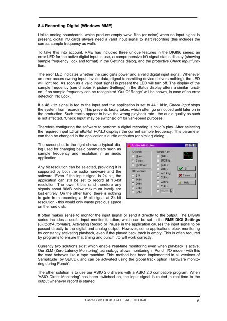
The screenshot to the right shows a typical dialog<br />
used for changing basic parameters such as<br />
sample frequency and resolution in an audio<br />
application.<br />
Any bit resolution can be selected, providing it is<br />
supported by both the audio hardware and the<br />
software. Even if the input signal is 24 bit, the<br />
application can still be set to record at 16-bit<br />
resolution. The lower 8 bits (and therefore any<br />
signals about <strong>96</strong>dB below maximum level) are<br />
lost entirely. On the other hand, there is nothing<br />
to gain from recording a 16-bit signal at 24-bit<br />
resolution - this would only waste precious space<br />
on the hard disk.<br />
It often makes sense to monitor the input signal or send it directly to the output. The <strong>DIGI</strong><strong>96</strong><br />
series includes a useful input monitor function, which can be set in the <strong>RME</strong> <strong>DIGI</strong> Settings<br />
(Output/Automatic). Activating Record or Pause in the application causes the input signal to be<br />
passed directly to the digital and analog output. However, some applications block monitoring<br />
by constantly activating playback, even if the played back track is empty. This is often required<br />
by programs to ensure that timing and punch I/O will work correctly.<br />
Currently two solutions exist which enable real-time monitoring even when playback is active.<br />
Our ZLM (Zero Latency Monitoring) technology allows monitoring in Punch I/O mode - with this<br />
the card behaves like a tape machine. This method has been implemented in all versions of<br />
Samplitude (by SEK’D), and can be activated using the global track option 'Hardware monitoring<br />
during Punch'.<br />
The other solution is to use our ASIO 2.0 drivers with a ASIO 2.0 compatible program. When<br />
'ASIO Direct Monitoring' has been switched on, the input signal is routed in real-time to the<br />
output whenever record is started.<br />
User's Guide <strong>DIGI</strong><strong>96</strong>/8 <strong>PAD</strong> © <strong>RME</strong> 9