Organic Optics and Electronics - Research Laboratory of Electronics ...
Organic Optics and Electronics - Research Laboratory of Electronics ...
Organic Optics and Electronics - Research Laboratory of Electronics ...

You also want an ePaper? Increase the reach of your titles
YUMPU automatically turns print PDFs into web optimized ePapers that Google loves.
Chapter 28. <strong>Organic</strong> <strong>Optics</strong> <strong>and</strong> <strong>Electronics</strong><br />
<strong>Organic</strong> <strong>Optics</strong> <strong>and</strong> <strong>Electronics</strong><br />
Academic <strong>and</strong> <strong>Research</strong> Staff<br />
Pr<strong>of</strong>. V. Bulović, Dr. Corinne Packard, Dr. Matthew Panzer, Dr. Jonathan (Yaakov) Tischler,<br />
Dr. Burag Yaglioglu, Dr. Ni Zhao<br />
Visiting Scientists <strong>and</strong> <strong>Research</strong> Affiliates<br />
T. Bloomstein (Lincoln <strong>Laboratory</strong>), T. Etheridge (HP), F. Jaworski (Raytheon), L. Rolly (HP)<br />
Graduate Students<br />
G. Akselrod, P. Anikeeva, A. Arango, S. Bradley, D. Friend, J. Ho, Q. Hu,<br />
T. Osedach, S. Paydavosi, J. Rowehl, Y. Shirasaki, H. Tang, V. Wood, J. Yu<br />
Technical <strong>and</strong> Support Staff<br />
M. Pegis, Admin. Asst.<br />
1. Electroluminescence from Phosphor-doped Nanocrystals<br />
Sponsors<br />
Institute for Soldier Nanotechnologies, PECASE, NDSEG<br />
Project Staff<br />
V. Wood, J. E. Halpert, M. J. Panzer, M.G. Bawendi, V. Bulović<br />
Alternating current thin-film electroluminescent (AC-TFEL) devices already occupy a segment <strong>of</strong> the<br />
large-area, high-resolution, flat-panel-display market. The AC-TFEL displays, which consist <strong>of</strong> a phosphor<br />
layer, such as manganese doped-zinc sulfide (ZnS:Mn), vertically s<strong>and</strong>wiched between two insulators<br />
that are contacted by electrodes, are robust, possess long lifetimes, <strong>and</strong> <strong>of</strong>fer high luminance with relatively<br />
low power consumption [1], [2]. While fabrication <strong>of</strong> AC-TFEL devices has been the subject <strong>of</strong> considerable<br />
study over the past three decades, significant challenges remain. Development <strong>of</strong> multicolor<br />
displays with balanced red, green, <strong>and</strong> blue (RGB) emission has proven difficult as the most efficient red,<br />
green, <strong>and</strong> blue phosphors comprise different materials systems that require different deposition <strong>and</strong> annealing<br />
steps. Transparent AC-TFEL displays have recently been demonstrated by Sharp, Inc.; however,<br />
the processing <strong>of</strong> the phosphor to achieve transparency is difficult <strong>and</strong> has not yet been developed for<br />
phosphors other than ZnS:Mn [3].<br />
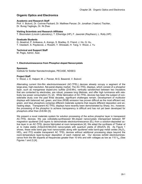
We present a novel materials system for solution processing <strong>of</strong> the active phosphor layer in transparent<br />
AC-TFEL devices. We use colloidally-synthesized Mn-doped nanocrystals interspersed between RF<br />
magnetron sputtered ZnS layers to demonstrate electroluminescence (EL) from a solution-deposited active<br />
layer in an AC-TFEL device fabricated at room temperature [4]. We adapt the synthesis <strong>of</strong> Thakar et<br />
al. to make stable ZnSe/ZnS:Mn/ZnS nanocrystals with quantum yields <strong>of</strong> (65±5)% [5]. As Figure 1<br />
shows, these wide b<strong>and</strong> gap host nanocrystals along with sputtered wide b<strong>and</strong>-gap metal oxides (Al 2 O 3 ,<br />
HfO 2 , <strong>and</strong> ITO) enable transparent AC TFEL devices without additional processing steps beyond the<br />
room-temperature layer-by-layer deposition <strong>of</strong> each material set. Our devices exhibit electroluminescence<br />
from the Mn dopants at frequencies greater than 10 kHz <strong>and</strong> with voltages as low as 110 V pp (See<br />
Figures 1 <strong>and</strong> 2) [4].<br />
28-1
Chapter 28. <strong>Organic</strong> <strong>Optics</strong> <strong>and</strong> <strong>Electronics</strong><br />
Figure 1: A photograph <strong>of</strong> a 0.5 in. x 0.5 in. glass<br />
substrate containing ten 1 mm x 2 mm AC-TFEL<br />
devices, with no bias applied. The substrate is pictured<br />
on top <strong>of</strong> printed text to demonstrate the transparency <strong>of</strong><br />
our AC-TFEL device architecture. The inset shows the<br />
uniformity <strong>of</strong> pixel illumination (in the dark) with the<br />
device operating at 170 V pp <strong>and</strong> 30 kHz.<br />
Figure 2: Electroluminescent (EL) spectra for devices<br />
with Al 2 O 3 <strong>and</strong> HfO 2 insulating layers (solid <strong>and</strong><br />
dashed orange curves, respectively). Photoluminescence<br />
(PL) spectra <strong>of</strong> the nanocrystal solution (solid<br />
gray curve) <strong>and</strong> a completed device (dashed black<br />
line). The overlap <strong>of</strong> the spectral peaks indicates that<br />
the emission is due to the Mn impurity dopants.<br />
References<br />
Y. A. Ono, Electroluminescent Displays. Singapore: World Scientific, 1995.<br />
J.P. Keir <strong>and</strong> J.F. Wager, “Electrical Characterization <strong>of</strong> Thin-Film Electroluminescent Devices,” Annu.<br />
Rev. Mat. Sci., vol 27, 1997, pp. 223-248.<br />
A. Abileah, K. Harkonen, A. Pakkala, <strong>and</strong> G. Smid. Transparent Electroluminescent (EL) Diplays, Planar<br />
Systems, 2008.<br />
V. Wood, J.E. Halpert, M.J. Panzer, M.G. Bawnedi, <strong>and</strong> V. Bulović. “AC-driven Electroluminescence from<br />
ZnSe/ZnS:Mn/ZnS Nanocrystals,” Nano Lett. in press, 2009.<br />
R. Thakar, Y. Chen, <strong>and</strong> P.T. Snee, “Efficient Emission from Core/(Doped) Shell Nanoparticles: Applications<br />
for Chemical Sensing,” Nano Lett., vol. 7, no. 11, Oct. 2007., pp. 3429-3432.<br />
2. Low-threshold Coherently-coupled <strong>Organic</strong> VCSEL<br />
Sponsors<br />
Institute for Soldier Nanotechnology<br />
Project Staff<br />
J. R. Tischler, E. R. Young, D. G. Nocera, V. Bulović<br />
Here we report observation <strong>of</strong> extremely low-threshold lasing in organic VCSELs when the excitons are<br />
coherently coupled non-radiatively to each other. Non-radiative coupling between excitons can enhance<br />
the emission cross-section <strong>of</strong> a gain material <strong>and</strong> lead to laser action at considerably lower excitation<br />
densities [1]. The coupling strength associated with the excitonic interaction is proportional to the number<br />
<strong>of</strong> excited molecules at any given time; hence the effect necessitates creating the exciton population<br />
quickly relative to the excited state decay time. This phenomenon is <strong>of</strong>ten referred to as superradiance<br />
[1], [2]. In organic semiconductor VCSELs, this effect leads to a 95% reduction in threshold when subpsec<br />
non-resonant excitation is utilized to create the exciton population, instead <strong>of</strong> a longer nsec duration<br />
pump pulse. The VCSELs consist <strong>of</strong> a thermally evaporated gain layer composed <strong>of</strong> the laser dye DCM<br />
doped (2.5 % v/v) into an Alq 3 host matrix, which is situated between a metal mirror <strong>and</strong> a dielectric Bragg<br />
28-2 RLE Progress Report 151
Chapter 28. <strong>Organic</strong> <strong>Optics</strong> <strong>and</strong> <strong>Electronics</strong><br />
reflector (DBR). In VCSELs where the gain layer is “λ/2n thick”, i.e., 156.7 nm, an extremely<br />
low threshold <strong>of</strong> 4.9 μJ/cm 2 is observed. This marks the first time lasing from organics has been<br />
reported in a metal/DBR half-wavelength thick microcavity, despite the rather modest resonator<br />
quality factor <strong>of</strong> Q < 200. Lasing is confirmed by supra-linear input-output power dependence<br />
<strong>and</strong> by spectral <strong>and</strong> spatial line-narrowing above the threshold. Moreover, when the optical excitation<br />
is polarized, the emission above the threshold strongly follows the polarization <strong>of</strong> the<br />
pump light. All prior demonstrations <strong>of</strong> laser action in solid-state organic VCSEL structures<br />
have utilized either gain layers <strong>of</strong> at least 3 times the thickness [3] or have relied on higher finesse<br />
<strong>of</strong> all dielectric microcavities [4]. The observed laser threshold <strong>of</strong> 4.9 μJ/cm 2 in the half-wavelength<br />
thick microcavity corresponds to excitation <strong>of</strong> at most 3.2% <strong>of</strong> the DCM molecules.<br />
Figure 1: Input/Output power dependence upon direct<br />
DCM excitation (λ ex = 535 nm) shows the lasing threshold<br />
at 4.9 μJ/cm 2 incident power <strong>and</strong> superlinear slope α =<br />
2.29 when fit to power law, y = mx α . Inset: Device design<br />
consists <strong>of</strong> a dielectric Bragg reflector (DBR), organic<br />
semiconductor gain layer, <strong>and</strong> silver mirror. The sample<br />
is excited at θ = 60° from normal using TM polarized laser<br />
light focused down to a spot size <strong>of</strong> 0.001 cm 2 as<br />
measured on the sample plane.<br />
Figure 2: Emission spectra <strong>of</strong> OVCSEL at different<br />
power levels above <strong>and</strong> below the threshold show<br />
linewidth narrowing from 2.5 nm for excitation below<br />
threshold ( , 3.25 μJ/cm 2 ; , 8 μJ/cm2) to 1.1 nm<br />
above threshold ( , 15 μJ/cm 2 ; , 250 μJ/cm 2 ).<br />
Inset: Emission cone spatially narrows from from Δθ<br />
= ± 30º to Δθ = ± 5º as measured at the emission<br />
peak.<br />
References<br />
L. Moi, P. Goy, M. Gross, J. M. Raimond, C. Fabre, <strong>and</strong> S. Haroche, “Rydberg-atom masers. I. A theoretical<br />
<strong>and</strong> experimental study <strong>of</strong> super-radiant systems in the millimeter-wave domain”, Physical Review<br />
A, vol. 27, pp. 2043-2064, April 1983.<br />
R. H. Dicke, “Coherence in Spontaneous Radiation Processes”, Physical Review, vol. 93, pp. 99-110,<br />
January 1954.<br />
V. Bulović, V. G. Kozlov, V. B. Khalfin, <strong>and</strong> S. R. Forrest, “Transform-limited, narrow-linewidth lasing action<br />
in organic semiconductor microcavities”, Science, vol. 279, pp. 553-555, January 1998.<br />
M. Koschorreck, R. Gehlhaar, V. G. Lyssenko, M. Swoboda, M. H<strong>of</strong>fmann, <strong>and</strong> K. Leo, “Dynamics <strong>of</strong> a<br />
high-Q vertical-cavity organic laser”, Applied Physics Letters, vol. 87, pp. 181108:1-3, October 2005.<br />
28-3
Chapter 28. <strong>Organic</strong> <strong>Optics</strong> <strong>and</strong> <strong>Electronics</strong><br />
3. Heterojunction Photovoltaics Using Printed Colloidal Quantum Dots<br />
Sponsors<br />
Institute for Soldier Nanotechnologies, DOE Solar America Program<br />
Project Staff<br />
A.C. Arango, S. Geyer, M.G. Bawendi, V. Bulović<br />
Colloidal quantum dot (QD) systems <strong>of</strong>fer distinct optical <strong>and</strong> electronic properties that are not easily attained<br />
by other nanostructured semiconductors, such as highly saturated emission in QD light-emittingdiodes,<br />
access to infrared radiation in QD photodetectors, <strong>and</strong> the prospect <strong>of</strong> optically optimized solar<br />
cell structures [1]. The prevailing deposition method for colloidal QD systems is spin-casting, which introduces<br />
limitations such as solvent incompatibility with underlying films <strong>and</strong> the inability to pattern side-byside<br />
pixels for multispectral photodetector arrays. In the present work we employ a non-destructive microcontact<br />
printing method [2], which allows for deposition <strong>of</strong> a thin quantum dot film onto a wide-b<strong>and</strong>gap<br />
organic hole transport layer, N,N'-Bis (3-methylphenyl)-N,N'-bis-(phenyl)-9,9-spiro-bifluorene (spiro-<br />
TPD), thus producing an inorganic/organic heterojunction that serves to enhance charge separation in the<br />
device. The top <strong>and</strong> bottom contacts are provided by ITO electrodes, allowing for near-transparency (Figure<br />
1).<br />
Restrictions imposed by transport losses in the QD film are found to limit charge generation. Measurements<br />
<strong>of</strong> the external quantum efficiency (EQE) <strong>and</strong> internal quantum efficiency (IQE) as a function <strong>of</strong> QD<br />
film thickness, plotted in Figure 2, reveal a marked dependence on thickness. The IQE is determined by<br />
dividing the EQE by the absorption <strong>of</strong> the QD film, all <strong>of</strong> which are measured at the first absorption peak<br />
<strong>of</strong> the QD film (λ = 590 nm). Following excitation <strong>and</strong> exciton diffusion to an interface, dissociation <strong>of</strong> the<br />
exciton produces free carriers that must diffuse to opposite electrodes in order to produce a photocurrent.<br />
A model that accounts for both exciton <strong>and</strong> charge diffusion reproduces the general thickness trend, assuming<br />
an exciton diffusion length L Ex = 43 nm, an electron diffusion length L El = 61 nm, <strong>and</strong> near-zero<br />
contribution from the first two QD monolayers. Further development will require reducing exciton <strong>and</strong><br />
charge transport losses in order to permit efficient charge-generation from thicker QD films with improved<br />
absorption.<br />
Figure 1: The QD heterojunction device architecture used in<br />
this work accommodates QD film thicknesses varying from 8<br />
to 80 nm.<br />
Figure 2: External quantum efficiency (EQE) (red squares)<br />
<strong>and</strong> internal quantum efficiency (IQE) (green circles) at λ =<br />
590 nm versus nominal QD film thickness <strong>and</strong> device<br />
absorption at λ = 590 nm. An analytical model for the EQE<br />
(red line) <strong>and</strong> IQE (green line) reproduces the general trend<br />
with thickness. Nominal thicknesses are calculated assuming<br />
an absorption coefficient <strong>of</strong> 10 4 cm -1 at λ = 590 nm.<br />
References<br />
D.C. Oertel, M.G. Bawendi, A.C. Arango, <strong>and</strong> V. Bulović. “Photodetectors based on treated CdSe quantum-dot<br />
films,” Applied Physics Letters, vol. 87, no. 21, p. 213505, Nov. 2005.<br />
A. C. Arango, D. C. Oertel, Y. Xu, M. G. Bawendi, <strong>and</strong> V. Bulović. “Heterojunction photovoltaics using<br />
printed colloidal quantum dots as a photosensitive layer,” Nano Letters, vol. 9, no. 2, pp. 860–863,<br />
Feb. 2009.<br />
28-4 RLE Progress Report 151
Chapter 28. <strong>Organic</strong> <strong>Optics</strong> <strong>and</strong> <strong>Electronics</strong><br />
4. Heterojunction Photodetector Consisting <strong>of</strong> Metal-oxide <strong>and</strong> Colloidal Quantum-dot Thin Films<br />
Sponsors<br />
Institute for Soldier Nanotechnologies, DOE Solar America Program<br />
Project Staff<br />
T. P. Osedach, N. Zhao, L.-Y. Chang, S. M. Geyer, A. C. Arango, J. C. Ho, M. Bawendi, V. Bulović<br />
We demonstrate a heterojunction photodetector consisting <strong>of</strong> a metal-oxide charge transport layer <strong>and</strong> a<br />
colloidal quantum-dot (QD) charge-generation layer. To make the device, a metal-oxide semiconductor,<br />
SnO 2 , is sputter-deposited over an array <strong>of</strong> interdigitated gold electrodes. A thin film <strong>of</strong> PbS QDs is then<br />
spin-coated over the structure (see Figure 1a). The optical <strong>and</strong> electrical characteristics <strong>of</strong> the device can<br />
be optimized independently through the modification <strong>of</strong> these two layers.<br />
The metal-oxide <strong>and</strong> QD layers form a type-II hetero-interface (Figure 1b) suitable for dissociating photogenerated<br />
excitons. Exciton dissociation at the interface results in the generation <strong>of</strong> holes in the QD layer<br />
<strong>and</strong> electrons in the metal-oxide layer. A bias corresponding to a field <strong>of</strong> ~10 4 V/cm is applied across the<br />
electrodes to facilitate carrier collection. The increased electron density increases the metal-oxide film<br />
conductivity, which in turn manifests an increase in lateral current through the device. A plot <strong>of</strong> the spectrally<br />
resolved external quantum efficiency is shown in Figure 2, with high efficiency response matching<br />
the spectral response <strong>of</strong> quantum-dot absorption.<br />
This work builds on previous reports from our laboratory in which an organic/organic photodetector [1]<br />
<strong>and</strong> an organic/QD photodetector [2] were described. The present device can be driven at reduced bias<br />
<strong>and</strong> extends spectral sensitivity into the infrared region. The unique ability to independently tune the optical<br />
<strong>and</strong> electrical characteristics <strong>of</strong> these structures makes them a valuable platform with which to study<br />
the physical processes at QD hetero-interfaces.<br />
Figure 1: (a) Schematic <strong>of</strong> the device structure. (b)<br />
Energy b<strong>and</strong> diagram. Excitons dissociate at the<br />
interface between the metal-oxide film <strong>and</strong> the<br />
quantum dots.<br />
Figure 2: External quantum efficiency spectrum (solid) <strong>and</strong> PbS QD absorption<br />
(dashed).<br />
References:<br />
J. Ho, A. Arango, <strong>and</strong> V. Bulović, “Lateral organic bilayer heterojunction photoconductors”, Appl. Phys.<br />
Lett. 2008.<br />
T. P. Osedach, S. M. Geyer, J. C. Ho, A. C. Arango, M. G. Bawendi, V. Bulović, “Lateral heterojunction<br />
photodetector consisting <strong>of</strong> molecular organic <strong>and</strong> colloidal quantum dot thin films”, Applied Physics<br />
Letters, January 2009.<br />
28-5
Chapter 28. <strong>Organic</strong> <strong>Optics</strong> <strong>and</strong> <strong>Electronics</strong><br />
5. Heterojunction Photoconductors for Chemical Detection<br />
Sponsors<br />
Institute for Soldiers Nanotechnology, Center for Materials Science <strong>and</strong> Engineering<br />
Project Staff<br />
J. C. Ho, J. A. Rowehl, V. Bulović<br />
We have developed <strong>and</strong> demonstrated a solid-state sensor platform that directly transduces the chemosignal<br />
<strong>of</strong> a fluorescent polymer-chemical interaction into photocurrent. In addition to the direct transduction<br />
mechanism, the sensor separates the chemosensing <strong>and</strong> conduction processes across the two different<br />
films, enabling independent optimization <strong>of</strong> each film to serve a specific function [1]. Conceptually,<br />
the device consists <strong>of</strong> a Type-II bilayer heterojunction deposited on planar electrodes that enables the<br />
application <strong>of</strong> an electric field in-plane with the interface. The bilayer heterojunction is realized by spincasting<br />
a chemosensitive fluorescent polymer on top <strong>of</strong> a sputtered metal oxide film.<br />
Figure 1 depicts device operation: 1) absorption <strong>of</strong> illumination creates excitons, 2) excitons diffuse to the<br />
interface, 3) b<strong>and</strong> <strong>of</strong>fsets enable efficient exciton dissociation into free carriers, <strong>and</strong> 4) transport <strong>of</strong> photogenerated,<br />
free carriers in the photoconductive channel. The presence <strong>of</strong> an analyte will strongly modulate<br />
the photoluminescence (PL) efficiency <strong>of</strong> the chemosensitive fluorescent polymer, which signifies a<br />
change in the population <strong>of</strong> excitons that can radiatively decay [2] . Altering the exciton population<br />
changes the carrier concentration at the heterointerface, which results in a change in the measured photocurrent.<br />
Initial testing <strong>of</strong> bilayer sensors, incorporating various polymers as the EGL <strong>and</strong> SnO 2 (doped 30% O 2 ) as<br />
the CTL, demonstrates an upper sensitivity limit to TNT detection <strong>of</strong> approximately 10 picograms <strong>of</strong> material<br />
in a few seconds. Figure 2 compares the spectral response <strong>of</strong> a 100-nm film <strong>of</strong> SnO 2 to a bilayer<br />
device (100 nm SnO 2 /5nm HW polymer) before <strong>and</strong> after exposure to saturated TNT vapor. The inset<br />
shows the real-time change in photoconductivity at the absorption peak <strong>of</strong> the polymer when TNT vapor is<br />
introduced at time t = 0. These results prove the bilayer sensor concept <strong>and</strong> hold promise for the development<br />
<strong>of</strong> a sensitive, highly specific, portable chemical sensor platform with potential for a wide array <strong>of</strong><br />
applications.<br />
Figure 1: Energy b<strong>and</strong> diagrams <strong>and</strong> cross-sections <strong>of</strong><br />
bilayer sensor consisting <strong>of</strong> an exciton generation layer<br />
(EGL) <strong>and</strong> a charge transport layer (CTL) before <strong>and</strong> after<br />
exposure to a particular analyte.<br />
Figure 2: Semilogarithmic spectral response plot <strong>of</strong><br />
HW polymer/SnO 2 bilayer sensor before (orange)<br />
<strong>and</strong> after (brown) saturated TNT vapor exposure.<br />
Response <strong>of</strong> 20-nm SnO 2 film (grey) is shown for<br />
comparison. Inset: Time response <strong>of</strong> TNT sensing<br />
action at t = 500 nm. TNT vapor is introduced at<br />
time t = 0 s.<br />
28-6 RLE Progress Report 151
Chapter 28. <strong>Organic</strong> <strong>Optics</strong> <strong>and</strong> <strong>Electronics</strong><br />
References<br />
J. Ho, A. Arango, <strong>and</strong> V. Bulović, “Lateral <strong>Organic</strong> Bi-layer Heterojunction Photoconductors,” Applied<br />
Physics Letters, vol. 93, 063305, August 2008.<br />
S. W. Thomas, G. D. Joly, <strong>and</strong> T. M. Swager, “Chemical Sensors Based on Amplifying Fluorescent Conjugated<br />
Polymers,” Chemical Review, vol. 107, pp. 1339-1386, March 2007.<br />
6. Multi-layer Heterojunction Photoconductors<br />
Sponsors<br />
Institute for Soldiers Nanotechnology Center for Materials Science <strong>and</strong> Engineering<br />
Project Staff<br />
J. C. Ho, J. A. Rowehl, V. Bulović<br />
We fabricate a two-terminal, lateral multi-layer photoconductor consisting <strong>of</strong> three molecular organic thin<br />
films with cascading energy b<strong>and</strong>s (see Figure 1): the charge transport layer (CTL), N,N'-bis(3-<br />
methylphenyl)-N,N'-diphenyl-1,1'-biphenyl-4,4'-diamine (TPD); the charge spacer layer (CSL), N,N'-bis-<br />
(1-naphthyl)-N,N' –diphenyl-1,1-bipheny1-4,4 ' -diamine (NPD); <strong>and</strong> the exciton-generation layer (EGL),<br />
3,4,9,10-perylenetetracarboxylic bis-benzimidazole (PTCBI). Placing an interstitial spacer layer between<br />
the CTL <strong>and</strong> the EGL improves the photogenerated current <strong>of</strong> tri-layer photoconductors over bi-layer,<br />
Type-II heterojunction photoconductors.<br />
Light excitation acts as a pseudo- “gate electrode” by generating excitons in PTCBI (EGL). Those excitons<br />
diffuse to the PTCBI/NPD interface, where they dissociate, leaving the electron behind in PTCBI,<br />
while the hole is initially injected into NPD from where it can transfer to the more energetically favorable<br />
states in TPD. Excess holes in the TPD film raise the hole-carrier concentration in the TPD film <strong>and</strong> increase<br />
the device conductance by forming a channel <strong>of</strong> excess carriers at the TPD/NPD interface. The<br />
thin film <strong>of</strong> NPD (CSL), between TPD (CTL) <strong>and</strong> PTCBI (EGL), spatially separates the dissociated carriers,<br />
reducing the likelihood <strong>of</strong> bimolecular recombination across the TPD/PTCBI interface. Bi-layer heterojunction<br />
photoconductors consisting <strong>of</strong> TPD <strong>and</strong> PTCBI alone have been shown to improve the external<br />
quantum efficiency over single layers <strong>of</strong> TPD <strong>and</strong> PTCBI by several orders <strong>of</strong> magnitude [1], [2]. Measurement<br />
<strong>of</strong> the current at an optical excitation wavelength <strong>of</strong> 532 nm from a biased multi-layer, lateral<br />
heterojunction device [Au/TPD(50 ± 0.5) nm/NPD(4 ± 1) nm/PTCBI(50 ± 0.5) nm] displays improvement<br />
by a factor <strong>of</strong> eight over the bi-layer without a CSL (see Figure 2). A thickness study <strong>of</strong> the NPD spacer<br />
layer experimentally demonstrates the dependence <strong>of</strong> the photoresponse efficiency on the spatial separation<br />
<strong>of</strong> the dissociated charge.<br />
28-7
Chapter 28. <strong>Organic</strong> <strong>Optics</strong> <strong>and</strong> <strong>Electronics</strong><br />
Figure 1: Energy-b<strong>and</strong> diagrams <strong>of</strong> (a) a bilayer device<br />
consisting <strong>of</strong> CTL/EGL <strong>and</strong> (b) a trilayer device consisting<br />
<strong>of</strong> CTL/CSL/EGL. Relevant interfacial recombination<br />
rates <strong>and</strong> carrier diffusion rates are depicted.<br />
Figure 2: Log-log current-voltage characteristics <strong>of</strong><br />
TPD 50 ± 0.5 nm TPD/NPD/50 ± 0.5 nm PTCBI, with<br />
0, 3.5, <strong>and</strong> 4 nm <strong>of</strong> NPD. Arrows indicate increasing<br />
NPD thickness <strong>and</strong> dashed red lines are guides that<br />
depict ohmic <strong>and</strong> trap-limited conduction.<br />
References<br />
J. Ho, J. Rowehl, <strong>and</strong> V. Bulović, “<strong>Organic</strong> Multi-layer Lateral Heterojunction Phototransistors,” presented<br />
at Electronic Materials Conference, Santa Barbara, CA, June 2008.<br />
J. Ho, A. Arango, <strong>and</strong> V. Bulović, “Lateral <strong>Organic</strong> Bi-layer Heterojunction Photoconductors,” Applied<br />
Physics Letters, vol. 93, 063305, August 2008.<br />
7. Three-molecular-layers-thick J-aggregate Photoconductor<br />
Sponsors<br />
MIT Institute for Soldier Nanotechnologies, Solar Revolutions Center at MIT, NSF Materials <strong>Research</strong><br />
Science <strong>and</strong> Engineering Center at MIT<br />
Project Staff<br />
Y. Shirasaki, J. Ho, M. S. Bradley, J. R. Tischler, V. Bulović<br />
Due to their record high absorption constant <strong>and</strong> narrow photoluminescence linewidth [1], thin films <strong>of</strong> J-<br />
aggregated cyanine dyes have been extensively studied with respect to their potential applications in<br />
novel opto-electronic devices, such as organic light emitting diodes, optical switches, <strong>and</strong> lasers. J aggregates’<br />
strong absorption is especially interesting for use in light sensing devices like a photoconductor. A<br />
J-aggregate film that is only a few nanometers thick, in conjunction with a dielectric mirror, has an ability<br />
to absorb almost 100% <strong>of</strong> incoming light [2] at normal incidence.<br />
We demonstrate in this study an efficient lateral J-aggregate photoconductor. Our device structure is a<br />
bi-layer heterojunction consisting <strong>of</strong> an optically active 5 nm thick TDBC J-aggregate thin film, which<br />
serves as the primary exciton generation layer, <strong>and</strong> a 50 nm layer <strong>of</strong> zinc indium oxide (ZIO) underneath,<br />
which serves as a charge transport layer. The contacts which sit below the ZIO are series <strong>of</strong> gold interdigitated<br />
fingers photolithographically defined on glass. The bi-layer structure physically separates the light<br />
absorption <strong>and</strong> charge transport regions <strong>of</strong> the device, taking advantage <strong>of</strong> the J aggregates’ unique optical<br />
properties <strong>and</strong> the ZIO’s charge transport properties. We observe that the heterojunction significantly<br />
increases the efficiency <strong>of</strong> the device by assisting the dissociation <strong>of</strong> the excitons, similar to the work reported<br />
by J. Ho et al [3]. External quantum efficiency (EQE), defined as the change in number <strong>of</strong> electrons<br />
passing through the bi-layer device per incident photon is shown in Figure 1. EQE greater than 100<br />
% suggests that the exciton recombination lifetime is greater than the transit time <strong>of</strong> the electrons passing<br />
through the device. The curve follows the absorption curve <strong>of</strong> ZIO <strong>and</strong> the J aggregates shown in the<br />
inset. Figure 2 shows the time response <strong>of</strong> the bi-layer device.<br />
28-8 RLE Progress Report 151
Chapter 28. <strong>Organic</strong> <strong>Optics</strong> <strong>and</strong> <strong>Electronics</strong><br />
We use PDMS lift-<strong>of</strong>f patterning <strong>of</strong> a thin film <strong>of</strong> thermally-evaporated TPD (N -bis(3-methylphenyl)-N,N -<br />
diphenyl-1,1 -biphenyl-4,4 -diamine) doped with DCM to form embossed pillars in the TPD film <strong>of</strong> 20-25<br />
nm in thickness. Figure 1a shows the device structure, Figure 1b shows PDMS lift-<strong>of</strong>f patterning technique,<br />
<strong>and</strong> Figure 1c shows the molecular diagrams <strong>of</strong> the device constituents. When the sample is optically<br />
excited with a ɭ=408 nm light source, emission from both the unpatterned (ɭ~630 nm) <strong>and</strong> patterned<br />
areas (ɭ~655 nm) is observed, as seen in Figure 2. The background emission dominates since its cavity<br />
resonance is closer to the resonance <strong>of</strong> DCM, as shown; use <strong>of</strong> different organic materials with larger lift<strong>of</strong>f<br />
amounts can increase this wavelength shift.<br />
Figure 1: (a) Patterned microcavity structure. (b) The<br />
PDMS lift-<strong>of</strong>f patterning process. (c) Molecular<br />
structures <strong>of</strong> constituent materials.<br />
Figure 2: Emission spectrum <strong>of</strong> DCM with unpatterned<br />
(background) <strong>and</strong> patterned microcavities when excited<br />
with λ=408 nm.<br />
References<br />
M. Sudzius, M. Langner, S. I. Hintschich, V. G. Lyssenko, H. Frob, <strong>and</strong> K. Leo, "Multimode laser emission<br />
from laterally confined organic microcavities," Applied Physics Letters, vol. 94, 2009.<br />
O. El Daif, A. Baas, T. Guillet, J. P. Brantut, R. I. Kaitouni, J. L. Staehli, F. Morier-Genoud, <strong>and</strong> B. Deveaud,<br />
"Polariton quantum boxes in semiconductor microcavities," Applied Physics Letters, vol. 88,<br />
2006.<br />
D. Bajoni, E. Peter, P. Senellart, J. L. Smirr, I. Sagnes, A. Lemaitre, <strong>and</strong> J. Bloch, "Polariton parametric<br />
luminescence in a single micropillar," Applied Physics Letters, vol. 90, 2007.<br />
J. Yu <strong>and</strong> V. Bulović, "Micropatterning metal electrode <strong>of</strong> organic light emitting devices using rapid polydimethylsiloxane<br />
lift-<strong>of</strong>f," Applied Physics Letters, vol. 91, 2007.<br />
J. Yu, “Improving OLED Technology for Displays,” Doctoral thesis, Elec. Eng. <strong>and</strong> Comp. Sci., Mass. Inst.<br />
<strong>of</strong> Tech., Cambridge, MA, 2008.<br />
9. Exciton-Exciton Annihilation in <strong>Organic</strong> Polariton Microcavities<br />
Sponsors<br />
CMSE, RLE, Hertz Foundation<br />
Project Staff<br />
G. M. Akselrod, J. R. Tischler, E. R. Young, M. S. Bradley, D. G. Nocera, V. Bulović<br />
Excitons in a solid can be coupled to the electromagnetic field by placing the material inside a resonantly<br />
tuned microcavity. If the decay rates <strong>of</strong> the excitons <strong>and</strong> the cavity mode are slower than the rate <strong>of</strong> energy<br />
exchange, the system takes on new eigenstates that are light-matter superpositions known as excitonpolaritons,<br />
<strong>and</strong> the limit <strong>of</strong> strong coupling is achieved. Recent work has demonstrated the use <strong>of</strong> organic<br />
thin films [1], [2] as the excitonic layer in polaritonic structures <strong>and</strong> the characteristic linear properties <strong>of</strong><br />
these devices showed strong coupling. We present the first in-depth study <strong>of</strong> high-intensity optical excitation<br />
<strong>of</strong> such organic exciton-polariton devices.<br />
28-10 RLE Progress Report 151
Chapter 28. <strong>Organic</strong> <strong>Optics</strong> <strong>and</strong> <strong>Electronics</strong><br />
The excitonic component <strong>of</strong> our devices was made <strong>of</strong> the 5.1 ± 0.1 nm film <strong>of</strong> J-aggregated cyanine dye<br />
TDBC assembled using layer-by-layer growth [3], giving an extremely high absorption coefficient <strong>of</strong> 10 6<br />
cm -1 . The cavity was formed by sputter-depositing a 4.5 pair distributed Bragg reflector (DBR) on a quartz<br />
substrate, followed by a λ/4n SiO 2 spacer layer, where n is the index <strong>of</strong> refraction <strong>and</strong> λ = 595 nm, the<br />
peak <strong>of</strong> the J-aggregate emission (Figure 1a). The J-aggregate film was then deposited, followed by a<br />
100±1 nm spin coated layer <strong>of</strong> polyvinyl alcohol, which enhances the photoluminscence quantum yield <strong>of</strong><br />
the J-aggregate film <strong>and</strong> acts as a spacer layer. A transparent thermally evaporated organic layer forms<br />
the remainder <strong>of</strong> the spacer, <strong>and</strong> the structure is capped with silver mirror, giving a cavity Q <strong>of</strong> ~60. The<br />
reflectivity as well as the photoluminscence (PL) <strong>of</strong> these devices shows two distinct resonances, which is<br />
characteristic <strong>of</strong> strong coupling (Figure 1).<br />
To test for evidence <strong>of</strong> polariton lasing, the devices were pumped at λ = 535 nm at 60° relative to normal<br />
<strong>and</strong> the PL was collected at normal incidence. To fully characterize the behavior <strong>of</strong> the devices in a wide<br />
range <strong>of</strong> power regimes, three pump sources were utilized: a CW laser at 532 nm, a 10-ns pulsed laser at<br />
535 nm, <strong>and</strong> a 150-fs pulsed laser at 535 nm. With CW excitation, all <strong>of</strong> the devices showed linear PL<br />
intensity as a function <strong>of</strong> input power. With 10-ns excitation, the PL began to show a sublinear power law<br />
dependence (p = 0.535), with the effect becoming more pronounced with 150-fs excitation (p = 0.348)<br />
(Figure 2a <strong>and</strong> b). Devices with a range <strong>of</strong> tunings as well as cavities with higher Q (~115) were tested<br />
<strong>and</strong> all showed the same qualitative sublinear behavior. A similar sublinear behavior was observed in J-<br />
aggregate thin films that were not situated in a cavity. We propose the process <strong>of</strong> exciton-exciton annhilation<br />
as a possible mechanism to explain the reduction <strong>of</strong> quantum yield with increasing intensity. Previous<br />
studies have shown the existence <strong>of</strong> exciton-exciton annihilation in cyanine dye J-aggregates [5], <strong>and</strong> it is<br />
a phenomenon observed in other excitonic materials that are c<strong>and</strong>idates for organic polariton lasing. Annihilation<br />
would be a process directly in competition with polariton-polariton scattering—inherently an exciton-exciton<br />
interaction—which is a possible mechanism for populating the k = 0 state <strong>of</strong> the polariton<br />
dispersion <strong>and</strong> achieving room- temperature organic polariton lasing.<br />
Figure 1: (a) A DBR-metal microcavity with a J-aggregate<br />
excitonic layer <strong>and</strong> a total optical thickness <strong>of</strong> ~λ/2 where λ = 595<br />
nm. (b) The reflectivity <strong>of</strong> devices having different cavity-exciton<br />
detunings <strong>and</strong> the corresponding PL.<br />
Figure 2: The PL vs. intensity for: microcavity<br />
pumped with 535 nm (a) 10 ns laser (b) 150<br />
fs laser; <strong>and</strong> a J-aggregate thin film pumped<br />
same two lasers.<br />
References<br />
D. G. Lidzey, D. D. C. Bradley, M. S. Skolnick, T. Virgili, S. Walker, <strong>and</strong> D. M. Whittaker, “Strong excitonphoton<br />
coupling in an organic semiconductor microcavity,” Nature, vol. 395 pp. 53-55, 1998.<br />
J. R. Tischler, M. S. Bradley, Q. Zhang, T. Atay, A. Nurmikko, <strong>and</strong> V. Bulović, “Solid state cavity QED:<br />
Strong coupling in organic thin films,” <strong>Organic</strong> <strong>Electronics</strong> vol. 8, no. 2-3, pp. 94-113, 2007.<br />
M. S. Bradley, J. R. Tischler, <strong>and</strong> V. Bulović, “Layer-by-layer J-aggregate thin films with a peak absorption<br />
constant <strong>of</strong> 10(6) cm(-1),” Advanced Materials, vol. 17, no. 15, pp. 1881-1884, 2005.<br />
L. Kelbauskas, S. Bagdonas, W. Dietel, <strong>and</strong> R. Rotomskis, “Excitation relaxation <strong>and</strong> structure <strong>of</strong> TPPS4<br />
J-aggregates,” Journal <strong>of</strong> Luminescence, vol. 101, pp. 253-262, 2003.<br />
28-11
Chapter 28. <strong>Organic</strong> <strong>Optics</strong> <strong>and</strong> <strong>Electronics</strong><br />
10. Strong Light-matter Coupling Using a Robust Non-cyanine Dye J-aggregate Material<br />
Sponsors<br />
Institute for Soldier Nanotechnology<br />
Project Staff<br />
J. R. Tischler, G. M. Akselrod, M. S. Bradley, J. Chan, E. R. Young, D. G. Nocera, T. M. Swager, V.<br />
Bulović<br />
We demonstrate strong light-matter coupling using a promising new J-aggregate material based on a dibenz[a,j]anthracene<br />
macrocycle [1], Figure 1a, that is robust under high power optical excitation. Strong<br />
light-matter coupling leads to polaritonic resonances that are superpositions <strong>of</strong> the underlying excitonic<br />
<strong>and</strong> photonic states [2] <strong>and</strong> can exhibit laser-like coherent light emission at remarkably low excitation<br />
densities due to polariton condensation [3]. A key hindrance to achieving polariton condensation thus far<br />
using cyanine dye J-aggregates has been exciton-exciton annihilation [4], which quenches excitations<br />
from the polaritonic states before they can condense. The J-aggregates <strong>of</strong> the dibenz[a,j]anthracenebased<br />
macrocycle show no signs <strong>of</strong> exciton-exciton annihilation until optical excitation densities exceeding<br />
20 MW/cm 2 , while in thin films <strong>of</strong> a typical J-aggregated cyanine dye, TDBC, annihilation appears at<br />
10 kW/cm 2 . Thin films <strong>of</strong> the macrocycle were prepared by spin-coating a 6 mg/ml solution <strong>of</strong> the dye in<br />
chlorobenzene, yielding layers that were 15 nm thick with an RMS roughness <strong>of</strong> less than 1 nm. The J-<br />
aggregation <strong>of</strong> the dye in these films was evidenced by the appearance <strong>of</strong> a narrow absorption line at 465<br />
nm <strong>of</strong> FWHM = 15 nm, Figure 1b, <strong>and</strong> the concomitant disappearance <strong>of</strong> the monomer absorption b<strong>and</strong><br />
as the dye concentration was increased [1]. The films possess an absorption coefficient <strong>of</strong> 2.1 x 10 5 cm -1<br />
at the J-aggregate absorption peak wavelength <strong>of</strong> 465 nm, show good photochemical stability, <strong>and</strong> have<br />
photoluminescence quantum yield exceeding 90%. Strong coupling was observed when thin films <strong>of</strong> the<br />
macrocycle were situated in a λ/2n planar optical microcavity consisting <strong>of</strong> a silver mirror <strong>and</strong> dielectric<br />
Bragg reflector. Devices exhibit polaritonic dispersion with a room temperature Rabi-splitting <strong>of</strong> 130 meV,<br />
Figure 2. Experiments are underway to demonstrate organic-based polariton condensation.<br />
Figure 1: (a) Chemical structure <strong>of</strong> dibenz[a,j]anthracene-based<br />
macrocycle. (b) Optical absorption <strong>and</strong> photoluminescence<br />
spectra from a thin film prepared by spin-coating the compound<br />
onto a glass substrate. Thin film roughness <strong>of</strong> less than 1 nm<br />
was observed in AFM.<br />
Figure 2: Polaritonic dispersion relation<br />
derived from angular device reflectance data.<br />
Anti-crossing <strong>of</strong> energy levels is observed at<br />
35º from normal.<br />
References<br />
J. M. W. Chan, J. R. Tischler, S. E. Kooi, V. Bulović, T. M. Swager, “Synthesis <strong>of</strong> J-Aggregating dibenz[a,J]anthracene-based<br />
macrocycles”, Journal <strong>of</strong> the American Chemical Society, vol. 131, pp.<br />
5659-5666, April 2009.<br />
28-12 RLE Progress Report 151
Chapter 28. <strong>Organic</strong> <strong>Optics</strong> <strong>and</strong> <strong>Electronics</strong><br />
C. Weisbuch, M. Nishioka, A. Ishikawa, <strong>and</strong> Y. Arakawa, “Observation <strong>of</strong> the coupled exciton-photon<br />
mode splitting in a semiconductor quantum microcavity”, Physical Review Letters, vol. 69, pp. 3314 –<br />
3317, May 1992.<br />
J. Kasprzak J, M. Richard, S. Kundermann, A. Baas, P. Jeambrun, J. M. J. Keeling, F. M. Marchetti, M. H.<br />
Szymanska, R. Andre, J. K. Staehli, V. Savona, P. B. Littlewood, B. Deveaud, L. S. Dang, “Bose-<br />
Einstein condensation <strong>of</strong> exciton polaritons”, Nature, vol. 443, pp. 409-414, September 2006.<br />
J. Moll, W. J. Harrison, D. V. Brumbaugh, A. A. Muenter, “Exciton annihilation in J-aggregates probed by<br />
femtosecond fluorescence upconversion”, Journal <strong>of</strong> Physical Chemistry A, vol. 104, pp. 8847-8854,<br />
October 2000.<br />
11. Molecules as Segmented Storage Elements in Floating Gate Memories<br />
Sponsors<br />
SRC/FCRP Focus Center on Materials Structures <strong>and</strong> Devices<br />
Project Staff<br />
S. Paydavosi, V. Bulović<br />
Conventional flash memories may reach fundamental scaling limits [1] because <strong>of</strong> the minimum tunnel<br />
oxide thickness <strong>and</strong> poor charge retention due to defects in the tunneling oxide, necessitating new approaches<br />
to meet the scaling requirements while simultaneously meeting the reliability <strong>and</strong> performance<br />
requirements <strong>of</strong> future products. In this study we demonstrate alternative nano-segmented floating gate<br />
memories using organic molecules as programmable charge-storage <strong>and</strong> charge-retention elements in<br />
capacitive structures. These organic thin films consist <strong>of</strong> inherently well-ordered planner molecules that<br />
are on the order <strong>of</strong> 1nm in size, representing a uniform set <strong>of</strong> identical nanostructured charge-storage<br />
centers. We investigated <strong>and</strong> compared the memory behavior <strong>of</strong> a variety <strong>of</strong> molecular thin films for identifying<br />
the molecular thin-film characteristics best suited for design <strong>of</strong> floating gate memory. The initial results<br />
show device durability over 10 5 program-erase cycles, with a hysteresis window <strong>of</strong> up to 3.3 V for<br />
program/erase conditions <strong>of</strong> +8V/-8V, corresponding to the charge storage density <strong>of</strong> 5 x 10 12 cm -2 . These<br />
results signify the potential <strong>of</strong> using molecular organic thin films as a floating gate <strong>of</strong> flash memory devices.<br />
200 nm Al<br />
15 nm Al 2 O 3<br />
10nm molecular<br />
floating gate<br />
4.8 nm SiO 2<br />
Alq 3<br />
PTCBI<br />
∆V=3.3±0.1<br />
V<br />
p-type Si substrate<br />
PTCDA<br />
C 60<br />
Figure 1: The schematic cross-section <strong>of</strong> the device structure<br />
with chemical structures <strong>of</strong> tested molecular organic thin<br />
films.<br />
Figure 2: The C-V plot <strong>of</strong> a device with a10-nm thick<br />
PTCBI layer showing a 3.3±0.1 V hysteresis window.<br />
References<br />
Pavan, P., Bez, R., Olivo, P. & Zanoni, E. Flash Memory Cells-An Overview. Proceedings <strong>of</strong> the IEEE 85,<br />
8 (1997).<br />
28-13
Chapter 28. <strong>Organic</strong> <strong>Optics</strong> <strong>and</strong> <strong>Electronics</strong><br />
12. Direct Patterning <strong>of</strong> Metallic MEMS through Microcontact Printing<br />
Sponsors<br />
DARPA, Hewlett-Packard<br />
Project Staff<br />
C. E. Packard, A. Murarka, V. Bulović<br />
St<strong>and</strong>ard photolithography-based methods for fabricating microelectromechanical systems (MEMS)<br />
present several drawbacks including expense, incompatibility with flexible substrates, <strong>and</strong> limitations to<br />
wafer-sized device arrays. We have developed a new fabrication method for rapid fabrication <strong>of</strong> largearea<br />
MEMS that breaks the paradigm <strong>of</strong> lithographic processing using a scalable, large area microcontact<br />
printing method to define three-dimensional electromechanical structures. Our PDMS Lift-Off Transfer<br />
(PLOT) involves the rapid removal <strong>of</strong> a pick-up stamp from a transfer pad to transfer a continuous metal<br />
film from the pad to the stamp. A stamp that forms the membrane suspension supports is fabricated by<br />
molding a thin layer <strong>of</strong> PDMS against a silicon master with a predefined relief. The metal membranes are<br />
deposited by thermal evaporation onto a transfer pad which has been prepared with an organic molecular<br />
release layer. To achieve transfer <strong>of</strong> the metal membrane over the supports <strong>of</strong> the device, the stamp is<br />
brought into conformal contact with the transfer pad <strong>and</strong> then released by rapidly peeling away. MEMS<br />
bridge structures, such as the ones shown in Figure 1, have been fabricated using PLOT, <strong>and</strong> their performance<br />
as variable capacitors has been characterized. In Figure 2, the capacitance <strong>of</strong> these devices<br />
increases with applied voltage, indicating mechanical deflection <strong>of</strong> the bridges due to the electrostatic<br />
force. PLOT forms MEMS structures without requiring elevated temperature processing, high pressure,<br />
or wet chemical or aggressive plasma release etches, providing compatibility with sensitive material sets<br />
for the fabrication <strong>of</strong> integrated micro- or opto-electronic/MEMS circuits. Flexible, paper-thin device arrays<br />
produced by this method may enable such applications as pressure sensing skins for aerodynamics,<br />
phased array detectors for acoustic imaging, <strong>and</strong> novel adaptive-texture display applications.<br />
Figure 1: Devices formed by PLOT: optical micrographs (a.<br />
& c.), schematic (b.) <strong>and</strong> photograph <strong>of</strong> devices formed on a<br />
flexible substrate (d.)<br />
Figure 2: Capacitance increases with applied<br />
voltage in two devices, indicating mechanical<br />
deflection <strong>of</strong> the bridging metal film.<br />
28-14 RLE Progress Report 151
Chapter 28. <strong>Organic</strong> <strong>Optics</strong> <strong>and</strong> <strong>Electronics</strong><br />
13. Surface Micromachining via Digital Patterning<br />
Sponsors<br />
DARPA, Hewlett-Packard<br />
Project Staff<br />
E.W. Lam, H. Li, V. Bulović, M.A. Schmidt<br />
Conventional microelectromechanical systems (MEMS) fabrication relies heavily on the semiconductor<br />
manufacturing paradigm. While this model is well-suited for planar devices such as integrated circuits, it is<br />
drastically limited in the design <strong>and</strong> fabrication <strong>of</strong> three-dimensional devices such as MEMS. From a<br />
commercial viewpoint, this paradigm also poorly fits MEMS because the lower market dem<strong>and</strong> makes it<br />
harder to <strong>of</strong>fset the high production costs. Ridding MEMS fabrication <strong>of</strong> its reliance on such techniques<br />
may introduce several advantages, namely a wider base <strong>of</strong> substrate materials as well as decreased<br />
manufacturing costs.<br />
Our project investigates severing MEMS fabrication from the traditional paradigm via digital patterning<br />
technologies. We have previously shown how MEMS can be used for the direct patterning <strong>of</strong> small molecular<br />
organics [1]. Using similar concepts, we have shown that surface micromachining can also be<br />
achieved.<br />
In 2007-2008, we identified a viable material set for our surface micromachining process’ sacrificial <strong>and</strong><br />
structural layers: poly-methylmethacrylate (PMMA) <strong>and</strong> silver nanoparticles. To account for surface nonuniformity<br />
<strong>of</strong> the deposited PMMA, we employed solvent vapors to effectively lower the polymer’s glass<br />
transition temperature <strong>and</strong> cause reflow at room temperatures [2]. To limit surface wetting <strong>and</strong> increase<br />
material loading <strong>of</strong> the silver nanoparticles, we deposited a PMMA reservoir to contain the silver nanoparticle<br />
solution (Figure 1). Free-st<strong>and</strong>ing cantilevers were fabricated (Figure 2), confirming that these techniques<br />
can be used for a surface micromachining process.<br />
The next stage will be to fabricate additional MEMS structures <strong>and</strong> test the silver nanoparticle’s mechanical<br />
properties. These properties will be used to design <strong>and</strong> fabricate a demonstration system based on<br />
our surface micromachining process. Subsequent stages will include creating a library <strong>of</strong> digital fabrication<br />
processes so that entire MEMS devices can be fabricated without the use <strong>of</strong> semiconductor manufacturing<br />
techniques.<br />
Figure 1: A silver surface micromachined cantilever fabricated using direct printing.<br />
References<br />
J. Chen, V. Leblanc, S.-H. Kang, M.A. Baldo, P.J. Benning, V. Bulović, <strong>and</strong> M.A. Schmidt, “Direct patterning<br />
<strong>of</strong> organics <strong>and</strong> metals using a micromachined printhead,” in Proc. MRS Spring 2005, San Francisco,<br />
CA, Mar./Apr. 2005, pp. H1.8:1-7<br />
J. Feng, M. Winnik, R.R. Shivers, <strong>and</strong> B. Clubb, “Polymer blend latex films: morphology <strong>and</strong> transparency,”<br />
Macromolecules, vol. 28, no. 23, pp. 7671-7682, Nov. 1995.<br />
28-15
Chapter 28. <strong>Organic</strong> <strong>Optics</strong> <strong>and</strong> <strong>Electronics</strong><br />
14. Effects <strong>of</strong> Bias Stress in <strong>Organic</strong> Thin-film Transistors<br />
Sponsors<br />
FCRP Focus Center for Circuit <strong>and</strong> Systems Solutions (C2S2)<br />
Project Staff<br />
K. Ryu, I. Nausieda, D. He, A. I. Akinw<strong>and</strong>e, V. Bulović, C. G. Sodini<br />
<strong>Organic</strong> transistor technology holds the promise <strong>of</strong> large-area flexible electronics <strong>and</strong> integration <strong>of</strong> various<br />
sensors <strong>and</strong> actuators on a single substrate [1]. However, current-voltage (I-V) characteristics <strong>of</strong> organic<br />
transistors are known to change with the application <strong>of</strong> prolonged voltages [2]. Such change,<br />
termed the bias-stress effect, leads to operational instability, which limits the usable lifetime <strong>of</strong> the circuit.<br />
The bias-stress effect must be understood <strong>and</strong> minimized to enable the use <strong>of</strong> organic transistors in functional<br />
applications. In this work, we present a method to accurately measure the bias-stress effect <strong>and</strong> a<br />
model that predicts the effect at different stress conditions. The model provides physical insight into the<br />
mechanisms causing the bias-stress effect <strong>and</strong> an estimate <strong>of</strong> the expected lifetime <strong>of</strong> the transistor. It<br />
also provides a means to determine the operating region that minimizes the bias-stress effect.<br />
To measure the bias-stress effect <strong>and</strong> no other degradation effects, we characterize pentacene OTFTs<br />
that have no measurable change due to storage in nitrogen ambient. We demonstrate that the afterstress<br />
I-V characteristics can be accurately described by the initial I-V characteristics <strong>and</strong> a shift in applied<br />
gate voltage, ΔV. Based on this observation, we characterize the bias-stress effect with ΔV. We<br />
measure ΔV at different gate <strong>and</strong> drain bias (V SG <strong>and</strong> V SD ) <strong>and</strong> stress times. Measurements with different<br />
V SD at fixed V SG stress show that ΔV decreases with increasing drain bias or current, indicating that gate<br />
field <strong>and</strong> channel carriers, not drain current, are responsible for the stress effect. We report that ΔV saturates<br />
independent <strong>of</strong> the V SG stress. We propose a simple carrier-trapping rate model that results in a<br />
stretched-exponential equation that accurately describes the observed ΔV behavior with respect to stress<br />
times. The model suggests that the bias-stress effect is caused by trapping <strong>of</strong> the channel carriers. The<br />
bias-stress effect saturates due to a constant number <strong>of</strong> trap sites, unlike in a-Si:H TFTs, where the trap<br />
sites are continually created until there are no more channel carriers [3]. The saturation <strong>of</strong> the bias-stress<br />
effect independent <strong>of</strong> the V SG stress is reported for the first time in organic transistors.<br />
Figure 1. Transfer characteristics after bias stress<br />
at V SG = 30 V, V SD = 1 V at varying stress time, t.<br />
The dashed line shows the shifted transfer characteristics<br />
<strong>of</strong> the unstressed device (t = 0 s).<br />
Figure 2. Measured stress time-dependence <strong>of</strong> the<br />
induced ΔV for different gate bias-stress conditions (colored<br />
dots) <strong>and</strong> the stretched-exponential fit made to the<br />
data (solid lines).<br />
28-16 RLE Progress Report 151
Chapter 28. <strong>Organic</strong> <strong>Optics</strong> <strong>and</strong> <strong>Electronics</strong><br />
References:<br />
I. Nausieda, K. Ryu, I. Kymissis, A.I. Akinw<strong>and</strong>e, V. Bulović, C.G. Sodini, “An organic active-matrix imager,”<br />
IEEE Transactions on Electron Devices, vol.55, pp. 527-532, Feb. 2008.<br />
S. J. Zilker, C. Detcheverry, E. Cantatore, <strong>and</strong> D. M. de Leeuw, “Bias stress in organic thin-film transistors<br />
<strong>and</strong> logic gates,” Appl. Phys. Lett. 79, 1124, Aug. 2001.<br />
W. B. Jackson, J. M. Marshall, M. D. Moyer, “Role <strong>of</strong> hydrogen in the formation <strong>of</strong> metastable defects in<br />
hydrogenated amorphous silicon,” Phys. Rev. B, 39, pp. 1164 – 1179, 1989.<br />
15. An <strong>Organic</strong> Thin-film Transistor Circuit for Large-area Temperature-sensing<br />
Sponsors<br />
FCRP Focus Center for Circuit <strong>and</strong> Systems Solutions (C2S2), Hewlett Packard, NSERC Fellowship<br />
Project Staff<br />
D. He, I. Nausieda, K. Ryu, A. I. Akinw<strong>and</strong>e, V. Bulović, C. G. Sodini<br />
The organic thin-film transistor (OTFT) is a field-effect transistor technology that uses organic materials as<br />
the semiconductor. OTFTs have field-effect mobilities that are comparable to those <strong>of</strong> hydrogenated<br />
amorphous silicon TFTs, <strong>and</strong> OTFTs are compatible with large-area <strong>and</strong> mechanically-flexible substrates<br />
[1], [2]. The goal <strong>of</strong> this work is to demonstrate an integrated OTFT temperature-sensing circuit suitable<br />
for large-area <strong>and</strong> flexible substrates.<br />
As shown in Figure 1, two important differences are observed between the OTFT’s <strong>and</strong> the MOSFET’s<br />
current-voltage characteristics when temperature is varied. First, the OTFT’s current increases with temperature<br />
in both subthreshold <strong>and</strong> above-threshold regimes, whereas the MOSFET’s above-threshold<br />
current decreases with temperature. Second, the OTFT’s subthreshold slope is temperature independent<br />
over the measured range <strong>of</strong> -20 to 60°C, while the MOSFET’s subthreshold slope is proportional-toabsolute-temperature<br />
(PTAT).<br />
Because <strong>of</strong> these differences in temperature response, the OTFT temperature-sensing “∆V BE circuit”<br />
(Figure 2a) has a complementary-to-absolute-temperature (CTAT) response instead <strong>of</strong> an equivalent silicon<br />
circuit’s PTAT response. The OTFT circuit is scaled to an array format to enable surface thermal<br />
sensing applications. As Figure 2b shows, the array consists <strong>of</strong> 3x3 temperature-sensing circuit cells <strong>of</strong><br />
1mm 2 each <strong>and</strong> is currently being characterized.<br />
28-17
Chapter 28. <strong>Organic</strong> <strong>Optics</strong> <strong>and</strong> <strong>Electronics</strong><br />
10 -6<br />
(A)<br />
I D<br />
[A]<br />
10 -4 V SG<br />
[V] @V SD<br />
= 20V<br />
10 -8<br />
10 -10<br />
10 -12<br />
60 o C<br />
40 o C<br />
20 o C<br />
0 o C<br />
-20 o C<br />
-5 0 5 10 15 20<br />
(A)<br />
1mm 2<br />
each<br />
10 -4 V SG<br />
[V] @V SD<br />
= 1.8V<br />
10 -6<br />
(B)<br />
I D<br />
[A]<br />
10 -8<br />
10 -10<br />
60 o C<br />
40 o C<br />
20 o C<br />
0 o C<br />
-20 o C<br />
(B)<br />
-0.5 -0.2 0.1 0.4 0.7 1<br />
Figure 1: (a) The OTFT’s (measured) <strong>and</strong> (b)<br />
pMOSFET’s (BSIM3) current-voltage characteristics<br />
versus temperature.<br />
Figure 2: (a) The CTAT circuit array schematic <strong>and</strong> (b)<br />
die photo.<br />
References:<br />
Y.Y. Lin, D.J. Gundlach, <strong>and</strong> T.N. Jackson, "High-mobility pentacene organic thin film transistors," Device<br />
<strong>Research</strong> Conference Digest, June 1996, pp. 80–81.<br />
I. Kymissis, C.G. Sodini, A.I. Akinw<strong>and</strong>e, <strong>and</strong> V. Bulović, “An organic semiconductor based process for<br />
photodetecting applications,” IEEE International Electron Devices Meeting Technical Digest, Dec.<br />
2004, pp. 377–380.<br />
16. Dual-threshold-voltage <strong>Organic</strong> Thin-film Transistors for Mixed-signal Integrated Circuits<br />
Sponsors<br />
FCRP Focus Center for Circuit <strong>and</strong> Systems Solutions (C2S2), Martin Family Fellowship<br />
Project Staff<br />
I. Nausieda, K. Ryu, D. He, A. I. Akinw<strong>and</strong>e,V. Bulović, C. G. Sodini<br />
<strong>Organic</strong> thin-film transistors (OTFTs) hold the potential for large-area, flexible electronics because their<br />
near-room-temperature processing enables them to be fabricated on plastic substrates. We have developed<br />
a low temperature (≤95°C) process to fabricate integrated OTFTs [1]. Designing circuits using<br />
OTFTs is challenging since only p-channel transistors are typically available. The OTFT technology limits<br />
noise margins in digital circuits due to the lack <strong>of</strong> an NMOS load, the location <strong>of</strong> the threshold voltage<br />
(V T ), <strong>and</strong> the availability <strong>of</strong> a single V T device [2]. We have addressed this problem by creating a dual V T<br />
process, with the addition <strong>of</strong> only one mask to pattern a second gate metal. We present positive noise<br />
margin inverters <strong>and</strong> a near rail-to-rail ring oscillator using a 3V supply. The ring oscillator output waveform<br />
is shown in Figure 1.<br />
28-18 RLE Progress Report 151
Chapter 28. <strong>Organic</strong> <strong>Optics</strong> <strong>and</strong> <strong>Electronics</strong><br />
The dual V T process enables analog integrated circuits. We demonstrate an uncompensated, two-stage<br />
operational amplifier with open loop gain <strong>of</strong> 36dB, unity gain frequency <strong>of</strong> ~7Hz, <strong>and</strong> common-mode rejection<br />
ratio (CMRR) <strong>of</strong> 20.1dB. The dual V T op amp has 30x better gain * -3dB frequency product than a<br />
single V T implementation <strong>and</strong> uses a 5V power supply. The op-amp frequency response is pictured in<br />
Figure 2.<br />
Figure 1: Schematic <strong>of</strong> 11-stage ring oscillator <strong>and</strong><br />
buffer (top). A 1.7 Hz output transient, indicating an<br />
inverter propagation delay <strong>of</strong> 27 ms.<br />
Figure 2: Schematic <strong>of</strong> opamp<br />
(top). Open loop<br />
frequency response <strong>of</strong> dual<br />
V T operational amplifier,<br />
indicating 2 poles (bottom).<br />
References:<br />
I. Nausieda, K. Ryu, I. Kymissis, A.I. Akinw<strong>and</strong>e, V. Bulović, C.G. Sodini, “An organic active-matrix imager,”<br />
IEEE Transactions on Electron Devices, vol.55, pp. 527-532, Feb. 2008.<br />
E. Cantatore, T.C.T. Geuns, G. Gelnick, E. van Veenendaal, A.F.A. Gruijthuijsen, L. Schrijnemakers, S.<br />
Drews, D.M de Leeuw, “A 13.56-MHz RFID system based on organic transponders,” IEEE Journal <strong>of</strong><br />
Solid-State Circuits, vol.42, pp.84-92. Jan. 2007.<br />
17. Reproducible Lithographically Patterned Metal-oxide Transistors for Large-area <strong>Electronics</strong><br />
Sponsors<br />
DARPA / FCRP Focus Center for Circuit <strong>and</strong> Systems Solutions (C2S2)<br />
Project Staff<br />
A. Wang, B. Yaglioglu, C. G. Sodini, V. Bulović, A. I. Akinw<strong>and</strong>e<br />
28-19
Chapter 28. <strong>Organic</strong> <strong>Optics</strong> <strong>and</strong> <strong>Electronics</strong><br />
Metal-oxide-based field-effect transistors (FETs) have been demonstrated with higher charge-carrier mobilities,<br />
higher current densities, <strong>and</strong> faster response performance than amorphous silicon FETs, which<br />
are the dominant technology used in display backplanes [1], [2]. Because the optically transparent semiconducting<br />
oxide films can be deposited at near-room temperatures, these materials are compatible with<br />
future generations <strong>of</strong> large-area electronics technologies that require flexible substrates [3]. Our project<br />
aims to develop a low-temperature, scalable lithographic process for metal oxide-based FETs that can be<br />
integrated into large-area electronic circuits.<br />
While any single demonstrated transistor may have excellent characteristics, circuit design using these<br />
FETs is impossible without the capability to reproducibly fabricate FETs with uniform characteristics. Previously,<br />
we demonstrated top-gate, fully lithographic FETs <strong>of</strong> varying channel lengths on 100-mm glass<br />
wafers with a sputtered ZnO:In 2 O 3 channel layer, using an organic polymer, parylene, as the gate dielectric<br />
<strong>and</strong> indium-tin-oxide (ITO) for source/drain contacts. Because <strong>of</strong> process non-uniformities, however,<br />
FET turn-<strong>of</strong>f voltages (V OFF ) across a wafer <strong>and</strong> between wafer lots varied by as much as ±10V. By modifying<br />
the process to deposit semiconductor <strong>and</strong> protective dielectric together without breaking vacuum,<br />
the FET uniformity across wafers was improved; the st<strong>and</strong>ard deviation <strong>of</strong> V OFF decreased to
Chapter 28. <strong>Organic</strong> <strong>Optics</strong> <strong>and</strong> <strong>Electronics</strong><br />
18. Stability <strong>of</strong> Metal Oxide-based Field-effect Transistors<br />
Sponsors<br />
Hewlett-Packard, DARPA<br />
Project Staff<br />
B. Yaglioglu, A. Wang, K. Ryu, C. Sodini, A. I. Akinw<strong>and</strong>e, V. Bulović<br />
The main goal <strong>of</strong> this research is to combine a low-temperature budget fabrication method with scalable<br />
processes such as sputter deposition to realize oxide channel field-effect transistors (FETs) on glass or<br />
flexible plastic substrates. Oxide-based transistors <strong>of</strong>fer an attractive alternative to commercially used<br />
amorphous Si transistors due to their high mobility values (~10-20cm 2 /Vs vs ~1cm 2 /Vs) [1-3]. Field-effect<br />
mobility, sub-threshold slope, <strong>and</strong> threshold voltage <strong>of</strong> FETs are the main parameters that are characterized<br />
for circuits. However, reliability <strong>of</strong> properties needs to be also addressed before these devices take<br />
their place in large-area electronic applications.<br />
In this study we test the stability <strong>of</strong> FETs that have a polymer dielectric, parylene, <strong>and</strong> an amorphous<br />
oxide semiconductor, zinc indium oxide. The devices are processed lithographically at low temperatures<br />
(T ≤ 100 ºC). Figure 1 shows a typical transfer characteristics curve representing device performance.<br />
The inset gives the distribution <strong>of</strong> the threshold voltage across a 4-inch wafer. In Figure 2, the change in I-<br />
V characteristics is shown under a prolonged gate bias stress. The gate bias is interrupted at fixed times<br />
to record the transfer characteristics <strong>of</strong> the transistor at a drain bias <strong>of</strong> V D =1V. Preliminary results <strong>of</strong> I-V<br />
tests show a positive shift in the threshold voltage. Two possible mechanisms that are originally proposed<br />
for similar shifts in amorphous Si FET’s are metastable state generation in the semiconductor <strong>and</strong> charge<br />
trapping in the dielectric [4]. Stability experiments at different temperatures <strong>and</strong> bias gate voltages are<br />
conducted to underst<strong>and</strong> the instability mechanisms in these hybrid (inorganic/organic) devices.<br />
1µ<br />
1.2µ<br />
I D<br />
, I G<br />
(A)<br />
100n<br />
10n<br />
1n<br />
100p<br />
10p<br />
1p<br />
I D<br />
I G<br />
Linear Fit<br />
V D<br />
=1V<br />
V T<br />
1/S<br />
# <strong>of</strong> devices<br />
6 maximum: 0.2 V<br />
minimum: -1.3 V<br />
5 mean: -0.54 V<br />
std. dev.: 0.37 V<br />
4<br />
3<br />
2<br />
1<br />
0<br />
-1.5 -1.0 -0.5 0.0 0.5<br />
V T<br />
I D<br />
(A)<br />
1.0µ<br />
800.0n<br />
600.0n<br />
400.0n<br />
200.0n<br />
0 s<br />
180 s<br />
900 s<br />
1800 s<br />
3600 s<br />
Stress Voltage: V G<br />
=20V<br />
100f<br />
0.0<br />
10f<br />
-6 -4<br />
V<br />
-2 0 2 4 6<br />
<strong>of</strong>f<br />
V G<br />
(V)<br />
-10 -5 0 5 10<br />
V G<br />
(V)<br />
Figure 1: Transfer characteristics <strong>of</strong> a<br />
W/L=100μ/100μ transistor. Data are taken from -5V to<br />
5V with 0.1V steps while V D = 1V. The distribution <strong>of</strong><br />
threshold voltage collected from 17 devices on<br />
different dies across the wafer is given in the inset.<br />
Figure 2: The V G -I D curve <strong>of</strong> a transistor as a function <strong>of</strong><br />
stress time. The stress measurement is interrupted every<br />
180s to measure the transfer characteristics.<br />
Measurements after 3min, 15min, 30min, <strong>and</strong> 1h are<br />
included to show the shift in the characteristics.<br />
References<br />
P.F. Carcia, R.S McLean, M.H. Reilly, <strong>and</strong> G. Nunes, “Transparent ZnO thin film transistors fabricated by<br />
rf magnetron sputtering,” Applied Physics Letters, vol. 82, no. 7, pp. 1117-1119, Feb. 2003<br />
28-21
Chapter 28. <strong>Organic</strong> <strong>Optics</strong> <strong>and</strong> <strong>Electronics</strong><br />
N.L. Dehuff, E.S. Kettenring, D. Hong, H.Q. Chiang, J.F. Wager, R.L. H<strong>of</strong>fman, C.H. Park, <strong>and</strong> D.A. Keszler,<br />
“Transparent thin film transistors with zinc indium oxide channel layer,” Journal <strong>of</strong> Applied Physics,<br />
vol. 97, no. 6, pp. 064505:1-5, Mar. 2005.<br />
H. Kumomi, K. Nomura, T. Kamiya, <strong>and</strong> H. Hosono, “Amorphous oxide channel TFTs,” Thin Solid Films,<br />
vol. 516, no. 7, pp.1516-1522, Feb. 2008.<br />
M.J. Powell, C. van Berkel, <strong>and</strong> J R. Hughes, “Time <strong>and</strong> temperature dependence <strong>of</strong> instability mechanisms<br />
in amorphous silicon thin-film transistors,” Applied Physics Letters, vol. 54, no.14, pp. 1323-<br />
1325, Jan. 1989.<br />
Publications<br />
Journal Articles, Published<br />
C. Madigan, E. Howe, V. Bulović, P. Mardilović, P. Kornilovitch, “Planarization in electrochemically fabricated<br />
nanodimensional films,” Journal <strong>of</strong> Physical Chemistry C 112, 7318 (2008).<br />
I. Nausieda, K. Ryu, I. Kymissis, A. Akinw<strong>and</strong>e, V. Bulović, C.G. Sodini, “An <strong>Organic</strong> Active-Matrix Imager,”<br />
IEEE Transactions on Electron Devices 55, 527 (2008).<br />
J.M. Caruge, J.E. Halpert, V. Wood, V. Bulović, <strong>and</strong> M.G. Bawendi, “Colloidal Quantum-Dot Light-Emitting<br />
Diodes with Metal-Oxide Charge Transport Layers,” Nature Photonics 2, 247 (2008).<br />
J. Yu <strong>and</strong> V. Bulović, “Using Integrated Optical Feedback to Counter Pixel Aging <strong>and</strong> Stabilize Light Output<br />
<strong>of</strong> <strong>Organic</strong> LED Display Technology,” IEEE Journal <strong>of</strong> Display Technology 4, 308 (2008).<br />
J. Ho, A. Arango, <strong>and</strong> V. Bulović, “Lateral <strong>Organic</strong> Bi-layer Heterojunction Photoconductors,” Applied<br />
Physics Letters 93, 063305 (2008).<br />
P.O. Anikeeva, C.F. Madigan, J.E. Halpert, M.G. Bawendi, V. Bulović, “Electronic <strong>and</strong> Excitonic<br />
Processes in Light-Emitting Devices Based on <strong>Organic</strong> Materials Colloidal Quantum Dots,” Physical Review<br />
B 78, 085434, (2008).<br />
M.S. Bradley, J.R. Tischler, Y. Shirasaki, <strong>and</strong> V. Bulović, “Predicting the Linear Optical Response <strong>of</strong> J-<br />
aggregate Microcavity Exciton-Polariton Devices,” Physical Review B 78, 193305 (2008).<br />
L. Kim, P.O. Anikeeva, S.A. Coe-Sullivan, J.S. Steckel, M.G. Bawendi, <strong>and</strong> V. Bulović, "Contact Printing<br />
<strong>of</strong> Quantum Dot Light-Emitting Devices," Nano Letters 8, 4513 (2008).<br />
A.C. Arango, D.C. Oertel, Y. Xu, M.G. Bawendi, <strong>and</strong> V. Bulović, "Heterojunction Photovoltaics Using<br />
Printed Colloidal Quantum Dots as a Photosensitive Layer," Nano Letters 9, 860 (2009).<br />
T.P. Osedach, S.M. Geyer, J.C. Ho, A.C. Arango, M.G. Bawendi, <strong>and</strong> V. Bulović, "Lateral Heterojunction<br />
Photodetector Consisting <strong>of</strong> Molecular <strong>Organic</strong> <strong>and</strong> Colloidal Quantum Dot Thin Films," Applied Physics<br />
Letters 94, 043307 (2009).<br />
A. Reina, X. Jia, J. Ho, D. Nezich, H. Son, V. Bulović, M.S. Dresselhaus, <strong>and</strong> J. Kong, "Large Area, Few-<br />
Layer Graphene Films on Arbitrary Substrates by Chemical Vapor Deposition," Nano Letters 9, 30 (2009).<br />
J.E. Halpert, J.R. Tischler, G. Nair, B.J. Walker, W. Liu, V. Bulović, M.G. Bawendi, “Electrostatic Formation<br />
<strong>of</strong> Quantum Dot/J-aggregate FRET Pairs in Solution,” Journal <strong>of</strong> Physical Chemistry C 113, 9986<br />
(2009).<br />
V. Wood, M.J. Panzer, J. Chen, M.S. Bradley, J.E. Halpert, M.G. Bawendi, <strong>and</strong> V. Bulović, "Inkjet-Printed<br />
Quantum Dot–Polymer Composites for Full-Color AC-Driven Displays," Advanced Materials 21, 2151<br />
(2009).<br />
28-22 RLE Progress Report 151
Chapter 28. <strong>Organic</strong> <strong>Optics</strong> <strong>and</strong> <strong>Electronics</strong><br />
V. Wood, J.E. Halpert, M.J. Panzer, M.G. Bawendi, V. Bulović, “Alternating Current Driven Electroluminescence<br />
from ZnSe/ZnS:Mn/ZnS Nanocrystals,” Nano Letters 9, 2367 (2009).<br />
J. Mei, M.S. Bradley, V. Bulović, “Photoluminescence quenching <strong>of</strong> tris-(8-hydroxyquinoline) aluminum<br />
thin films at interfaces with metal oxide films <strong>of</strong> different conductivities,” Physical Review B 79, 235205<br />
(2009).<br />
J.M.W. Chan, J.R. Tischler, S.E. Kooi, V. Bulović, T.M. Swager “Synthesis <strong>of</strong> J-Aggregating Dibenz[a,J]anthracene-Based<br />
Macrocycles,” Journal <strong>of</strong> American Chemical Society 131, 5659 (2009).<br />
Theses<br />
Ph.D. Thesis:<br />
Yu, J. (V. Bulović), “Improving OLED Technology for Displays,” Sep. 2008 (EECS).<br />
Anikeeva, P. (V. Bulović), “Physical Properties <strong>and</strong> Design <strong>of</strong> Light-Emitting Devices Based on <strong>Organic</strong><br />
Materials <strong>and</strong> Nanoparticles,” Feb. 2009 (DMSE).<br />
Bradley, M.S. (V. Bulović), “Engineering J-Aggregate Cavity Exciton-Polariton Devices,” June 2009<br />
(EECS).<br />
Ho, J. (V. Bulović), “<strong>Organic</strong> Lateral Heterojunction Devices for Vapor-phase Chemical Detection,” June<br />
2009 (EECS).<br />
M.Eng. Thesis:<br />
Shirasaki, Y. (V. Bulović), “Efficient Förster Energy Transfer From Phosphorescent <strong>Organic</strong> Molecules to<br />
J-aggregate Thin Film,” February 2008 (EECS).<br />
Abdu, H. (V. Bulović), “Molecular <strong>and</strong> Quantum Dot Floating Gate Non-Volatile Memories,” June 2008<br />
(EECS).<br />
Friend, D. (V. Bulović), “Theory <strong>and</strong> Fabrication <strong>of</strong> Evanescently-Coupled Photoluminescent Devices,”<br />
June 2008 (EECS).<br />
Tang, H. (V. Bulović), “Near Room Temperature Lithographically Processed Metal-Oxide Transistors,”<br />
June 2008 (EECS).<br />
28-23