Die Mount Cam - Ridix
Die Mount Cam - Ridix
Die Mount Cam - Ridix

You also want an ePaper? Increase the reach of your titles
YUMPU automatically turns print PDFs into web optimized ePapers that Google loves.
TRUSTED SOLUTIONS AND INNOVATION<br />
AERIAL & DIE MOUNT<br />
CAMS CATALOG
www.danly.com<br />
AERIAL & DIE MOUNT CAMS<br />
Service We Deliver and Quality You Can Depend On<br />
IEM is a leading manufacturer of die sets and die component products supplied globally to the parts<br />
forming industry. Backed by years of tool and die experience, quality and innovation are some of the<br />
reasons why our name is respected throughout the world. We have taken the lead role in creating<br />
and bringing new products to customers and helping them find solutions that improve their operations.<br />
Based on the capabilities IEM offers, we can help you to meet the demands of quick deliveries,<br />
technical support, quality products and competitive prices. IEM and its’ broad distribution channels<br />
and direct sales personnel will assist you in any way to make your product a better and more<br />
profitable one.<br />
Whether you purchase on-line or in person, you will receive the same reliable service IEM is known<br />
for. We understand the demanding schedules of die builders and production personnel and have<br />
developed efficient manufacturing processes to shorten product lead times as well as put inventory<br />
on our shelves so you can have it in your facility when you need it. Put the IEM network to work for<br />
you. We’ve got the service you’ve been looking for.<br />
Included in our full line offering are both inch and metric size die sets and die components that<br />
are designed to numerous die standards including ISO, NAAMS, JIS and many large automotive<br />
and appliance manufacturers’ standards. The complete product offering includes:<br />
• Ball bearing and friction style die sets including custom and catalog sets<br />
• Machined plate<br />
• Guide posts & bushings<br />
• ISO and JIS <strong>Die</strong> Springs<br />
• In-die tapping units for both mechanical and hydraulic presses<br />
• Formathane ® Urethane springs, strippers, sheets, bars, rods and die cover film<br />
• <strong>Die</strong>makers’ supplies such as pry bars, dowel pins, hoist rings, clamps and fasteners<br />
• Standard and self-lubricating wear product including wear plate, wear strips, gibs,<br />
keeper plates and guide blocks<br />
• <strong>Cam</strong> units, including Mini TM , Aerial and <strong>Die</strong> <strong>Mount</strong> styles<br />
• Accu-Bend TM Rotary Benders<br />
• Standard and Ball lock punches and retainers<br />
• Air presses<br />
• Pad retainers<br />
• Nitrogen gas springs
CONTENTS<br />
PAGE NUMBER<br />
<strong>Cam</strong> Selection Matrix 2<br />
General Information 3<br />
NAAMS Standards Aerial <strong>Cam</strong>s<br />
50 mm 4<br />
75 mm 6<br />
125 mm 8<br />
150 mm 10<br />
175 mm 12<br />
200 mm 14<br />
250 mm 16<br />
300 mm 18<br />
NAAMS Standards <strong>Die</strong> <strong>Mount</strong> <strong>Cam</strong>s<br />
50 mm 20<br />
75 mm 22<br />
150 mm 24<br />
200 mm 26<br />
250 mm 28<br />
300 mm 33<br />
Long Reaching (Extra Travel)<br />
<strong>Die</strong> <strong>Mount</strong> <strong>Cam</strong>s (LRD)<br />
When to Use a LRD <strong>Cam</strong> 33<br />
75 mm 34<br />
150 mm 36<br />
200 mm 38<br />
Calculation of Load and Stroke 40<br />
Ask Customer Service for design templates on our website or CD.<br />
Picture not representative of all angles.<br />
1<br />
All dimensions are for reference only.<br />
No tolerance is stated or implied.
S<br />
Ask Customer Service for design templates on our website or CD.<br />
Picture not representative of all angles.<br />
<strong>Cam</strong> Selection Matrix<br />
Gib TM Mini TM<br />
Nitrogen Return Option – Using nitrogen springs to replace the<br />
standard mechanical springs will provide more slide return force for applications<br />
involving heavier tooling mounted on the slide face. Individual return forces<br />
can be found on the specifications table for each size cam.<br />
Positive Return – Included are mechanical return straps designed<br />
into the cam to pull the slide and tooling out of the part in case of a tooling<br />
jam. Positive return straps are designed to provide a positive return but are<br />
not designed to provide continuous stripping force.<br />
Electronic Templates Available – Each cam has Template or<br />
Model files saved for easy download into your die designs. The slide, body and<br />
driver are broken into three components for die movement simulation. The<br />
formats available are 2D/3D DWG, IGES, STEP, Parasolid, Catia, and<br />
Solidworks.<br />
Special <strong>Cam</strong> Designs – We know there are sometimes when a<br />
standard cam doesn't fit into an application or is at the wrong angle. If you<br />
provide us with your application specifications, we will design and build a<br />
special cam for you.<br />
Long Reach Box<br />
(Extra Travel)<br />
2<br />
Standard Box<br />
Max Power TM<br />
Box (MP)<br />
Milfab ®<br />
NDM <strong>Die</strong> <strong>Mount</strong>s<br />
NAAMS<br />
Standards<br />
NAC Aerial<br />
Inch X X X X<br />
Metric X X X X X X X X X<br />
Low profile X X<br />
Narrow width X X X<br />
Short length X X X X<br />
Maximum<br />
slide travel X X<br />
Maximum<br />
stripping force X X<br />
Nitrogen Return X X X X X<br />
Positive return X X X X X<br />
Maximum<br />
piercing force X X X X X<br />
Designed to<br />
NAAMS Standards X X<br />
Special <strong>Cam</strong><br />
Designs Available X X X X X X X X X<br />
Long Reaching<br />
(Extra Travel)<br />
<strong>Die</strong> <strong>Mount</strong><br />
Items in<br />
the blue<br />
shaded<br />
area are<br />
included<br />
in this<br />
catalog.<br />
All dimensions are for reference only.<br />
No tolerance is stated or implied.
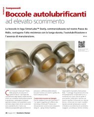
Product Information<br />
Product Features<br />
Every NAAMS cam provides excellent<br />
performance and is designed with heavy-duty<br />
high volume production in mind.<br />
♦ Self lubricating sliding surfaces provide<br />
maintenance free operation.<br />
♦ Aluminum Bronze against steel wear surfaces<br />
is standard with an option of steel on steel<br />
wear surfaces.<br />
NAC075-20<br />
NAAMS<br />
Aerial <strong>Cam</strong><br />
♦ Slide accelerators are added to certain angles<br />
for quiet operation & reduced wear.<br />
♦ Positive return(s) on the cam slide assures<br />
slide retraction and extra protection.<br />
♦ Ease of setup with home position slide lockout<br />
capabilities.<br />
♦ Rear spring access for ease of maintenance.<br />
♦ Quick slide removal with top access keeper<br />
plate for all die mount cams.<br />
NDM075-00<br />
NAAMS<br />
<strong>Die</strong> <strong>Mount</strong> <strong>Cam</strong><br />
Ask Customer Service for design templates on our website or CD.<br />
Picture not representative of all angles.<br />
3<br />
All dimensions are for reference only.<br />
No tolerance is stated or implied.
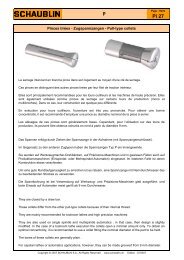
Aerial <strong>Cam</strong> – 50 mm<br />
9<br />
0<br />
9<br />
0<br />
13<br />
2X ø12<br />
DOWELS<br />
TOP VIEW<br />
212<br />
WORK<br />
ANGLE Z<br />
0 - 15° 147.5<br />
20 - 60° 127.5<br />
SLIDE<br />
TRAVEL<br />
30 mm<br />
WORK<br />
TRAVEL<br />
PRESS<br />
TRAVEL<br />
ADAPTER<br />
ANGLE<br />
WORK<br />
ANGLE<br />
2X M12<br />
MOUNTING<br />
SCREWS<br />
CAM MOTION<br />
225<br />
E<br />
C<br />
N<br />
80 12<br />
J<br />
A<br />
225<br />
SLIDE<br />
TRAVEL<br />
WORK<br />
TRAVEL<br />
WORK<br />
ANGLE<br />
67<br />
Y<br />
TOOLING<br />
FACE CL<br />
TOOLING<br />
BALL CL<br />
94.1<br />
MAX.<br />
CUSTOMER<br />
SUPPLIED<br />
BACK KEY<br />
REF.<br />
H<br />
D<br />
P<br />
50<br />
80<br />
TOOLING MOUNTING FACE<br />
SIDE VIEW<br />
9<br />
0<br />
9<br />
0<br />
12.5<br />
Z<br />
BOTTOM VIEW (Driver Only)<br />
2X ø12<br />
DOWELS<br />
2X M12<br />
MOUNTING<br />
SCREWS<br />
Tooling ball is not supplied<br />
with the cam and is<br />
a reference point only.<br />
Ø12<br />
12<br />
NAAMS TOOLING BALL<br />
Ask Customer Service for design templates on our website or CD.<br />
Picture not representative of all angles.<br />
4<br />
Tooling ball located at “A” dimension per NAAMS.<br />
“Y” dimension represents the tooling ball from the slide centerline.<br />
Dowel holes undersized 0.2/0.3mm.<br />
All dimensions are for reference only.<br />
No tolerance is stated or implied.
Aerial <strong>Cam</strong> – 50 mm<br />
NUMBERING EXAMPLE<br />
N A C 0 5 0 - 25 X<br />
NAAMS Standards Aerial <strong>Cam</strong><br />
Face Width<br />
Working Angle<br />
SUFFIX (Optional)<br />
N2 = Nitrogen Gas Spring (2000 psi)<br />
AA85 = Obtain this number from Customer Service (for special angles)<br />
Part NAAMS Work Adapt Work<br />
Number Number Angle Angle Travel A C D E H J N P Y<br />
(mm) (mm) (mm) (mm) (mm) (mm) (mm) (mm) (mm) (mm)<br />
NAC050-00 C130500 0 50 19.3 120 155.5 150.5 241.9 160.0 -12.0 -16.9 -9.5 1.1<br />
NAC050-05 C130505 5 45 21.3 125 149.5 153.0 237.5 160.0 -8.3 -12.5 -7.0 2.0<br />
NAC050-10 C130510 10 40 23.3 130 145.0 160.1 231.0 160.0 -4.1 -6.0 0.1 4.4<br />
NAC050-15 C130515 15 35 25.5 135 140.5 166.9 228.6 160.0 -0.4 -3.6 6.9 6.0<br />
NAC050-20 C130520 20 30 27.7 140 134.5 151.9 220.3 140.0 5.1 4.7 11.9 7.4<br />
NAC050-25 C130525 25 25 30.2 145 130.0 156.9 213.5 140.0 9.8 11.5 16.9 8.2<br />
NAC050-30 C130530 30 20 32.9 150 125.5 163.1 205.6 140.0 14.1 19.4 23.1 7.7<br />
NAC050-35 C130535 35 15 35.7 155 119.5 163.0 198.1 140.0 18.5 26.9 23.0 7.7<br />
NAC050-40 C130540 40 10 38.9 160 115.0 167.0 188.0 140.0 22.1 37.0 27.0 6.7<br />
NAC050-45 C130545 45 5 42.7 165 110.5 168.8 180.9 140.0 25.1 44.1 28.8 5.3<br />
NAC050-50 C130550 50 0 47.1 170 106.0 171.0 174.5 140.0 27.7 50.5 31.0 4.0<br />
NAC050-55 C130555 55 0 52.7 175 101.5 171.1 167.6 140.0 28.8 57.4 31.1 2.0<br />
NAC050-60 C130560 60 0 60.4 180 98.5 174.3 162.8 140.0 28.1 62.2 34.3 -0.3<br />
Max. Mechanical Nitrogen Maximum Maximum Approx.<br />
Work Slide Spring Spring Tooling Tooling <strong>Cam</strong> Unit<br />
Force Travel Return Return Weight Envelope 2 Weight<br />
Force Force 1<br />
Final Final Weight Weight Protrusion Tooling<br />
(KN/Tons) (mm) (Kg/Lbs) (Kg/Lbs) (Kg/Lbs) (Kg/Lbs) (mm) Overhang (Kg/Lbs)<br />
[One Spring] [One Spring] Mechanical Nitrogen per side of<br />
Spring Spring Slide (mm)<br />
134/15 30 153/338 94/208 8/18 16/35 125 20 21/45<br />
1<br />
Optional nitrogen cylinders do not have a pre-load. Listed nitrogen ratings are at the end of their stroke.<br />
2<br />
Exceeding the maximum tooling envelope will reduce cam performance and shorten the life of the cam.<br />
Adapter<br />
+<br />
sin ( Work<br />
)<br />
PRESS<br />
TRAVEL = Work Travel x Angle Angle<br />
cos (Adapter Angle)<br />
Ask Customer Service for design templates on our website or CD.<br />
Picture not representative of all angles.<br />
5<br />
All dimensions are for reference only.<br />
No tolerance is stated or implied.
Aerial CAM – 75 mm<br />
45<br />
0<br />
45<br />
0<br />
18<br />
48<br />
2X ø12<br />
DOWELS<br />
TOP VIEW<br />
Q<br />
4X M12<br />
MOUNTING<br />
SCREWS<br />
WORK<br />
ANGLE Q Z<br />
0° 272 18.5<br />
5° 282 18.5<br />
10° 292 18.5<br />
15° 287 18.5<br />
20° 292 22.5<br />
25° 282 22.5<br />
30° 292 22.5<br />
35° 287 22.5<br />
40° 287 22.5<br />
45° 287 22.5<br />
50° 277 22.5<br />
55° 277 22.5<br />
60° 277 22.5<br />
SLIDE<br />
TRAVEL<br />
50 mm<br />
WORK<br />
TRAVEL<br />
ADAPTER<br />
ANGLE<br />
PRESS<br />
TRAVEL<br />
CAM MOTION<br />
WORK<br />
ANGLE<br />
G<br />
E<br />
C<br />
N<br />
115<br />
12<br />
A<br />
J<br />
275<br />
SLIDE<br />
TRAVEL<br />
WORK<br />
TRAVEL<br />
TOOLING<br />
FACE CL<br />
TOOLING<br />
BALL CL<br />
WORK<br />
ANGLE<br />
102 154.3<br />
MAX.<br />
Y<br />
95<br />
CUSTOMER<br />
SUPPLIED<br />
BACK KEY<br />
REF.<br />
195<br />
D<br />
P<br />
75<br />
TOOLING MOUNTING FACE<br />
SIDE VIEW<br />
Z<br />
0<br />
Z<br />
4X M12<br />
MOUNTING<br />
SCREWS<br />
2X ø12<br />
DOWELS<br />
Ø12<br />
12<br />
0<br />
15<br />
180<br />
BOTTOM VIEW (Driver Only)<br />
Tooling ball is not supplied<br />
with the cam and is<br />
a reference point only.<br />
NAAMS TOOLING BALL<br />
Ask Customer Service for design templates on our website or CD.<br />
Picture not representative of all angles.<br />
6<br />
Tooling ball located at “A” dimension per NAAMS.<br />
“Y” dimension represents the tooling ball from the slide centerline.<br />
Dowel holes undersized 0.2/0.3mm.<br />
All dimensions are for reference only.<br />
No tolerance is stated or implied.
Aerial CAM – 75 mm<br />
NUMBERING EXAMPLE<br />
N A C 0 7 5 - 25 X<br />
NAAMS Standards Aerial <strong>Cam</strong><br />
Face Width<br />
Working Angle<br />
SUFFIX (Optional)<br />
N2 = Nitrogen Gas Spring (2000 psi)<br />
AA85 = Obtain this number from Customer Service (for special angles)<br />
Part NAAMS Work Adapt Work<br />
Number Number Angle Angle Travel A C D E G J N P Y<br />
(mm) (mm) (mm) (mm) (mm) (mm) (mm) (mm) (mm) (mm)<br />
NAC075-00 C130700 0 50 32.1 155 180.0 210.1 330.0 290 -12.0 -40.0 15.1 15.0<br />
NAC075-05 C130705 5 45 35.5 160 160.5 217.5 330.2 300 -6.6 -30.2 22.5 14.4<br />
NAC075-10 C130710 10 40 38.9 165 153.0 224.7 330.4 310 -1.3 -20.4 29.7 13.2<br />
NAC075-15 C130715 15 35 42.4 170 144.0 230.9 320.0 305 4.3 -15.0 35.9 13.9<br />
NAC075-20 C130720 20 30 46.1 175 136.5 237.6 315.0 310 8.9 -5.0 42.6 11.5<br />
NAC075-25 C130725 25 25 50.0 180 127.5 246.6 300.0 300 10.4 0.0 51.6 2.8<br />
NAC075-30 C130730 30 20 54.3 185 120.0 254.0 300.0 310 12.6 10.0 59.0 -1.5<br />
NAC075-35 C130735 35 15 59.0 190 112.5 261.8 285.0 305 13.6 20.0 66.8 -6.7<br />
NAC075-40 C130740 40 10 64.3 195 105.0 270.4 275.0 305 12.9 30.0 75.4 -13.2<br />
NAC075-45 C130745 45 5 70.4 200 99.0 274.9 265.0 305 15.1 40.0 79.9 -14.1<br />
NAC075-50 C130750 50 0 77.8 205 93.0 278.6 263.6 295 17.2 31.4 83.6 -15.0<br />
NAC075-55 C130755 55 0 87.2 210 72.0 267.5 240.9 295 33.8 54.1 72.5 2.2<br />
NAC075-60 C130760 60 0 100.0 215 79.0 282.0 246.8 295 24.9 48.2 87.0 -11.8<br />
Max. Mechanical Nitrogen Maximum Maximum Approx.<br />
Work Slide Spring Spring Tooling Tooling <strong>Cam</strong> Unit<br />
Force Travel Return Return Weight Envelope 2 Weight<br />
Force Force 1<br />
Final Final Weight Weight Protrusion Tooling<br />
(KN/Tons) (mm) (Kg/Lbs) (Kg/Lbs) (Kg/Lbs) (Kg/Lbs) (mm) Overhang (Kg/Lbs)<br />
[One Spring] [One Spring] Mechanical Nitrogen per side of<br />
Spring Spring Slide (mm)<br />
134/15 50 220/485 316/697 12/26 24/53 140 20 46/100<br />
1<br />
Optional nitrogen cylinders do not have a pre-load. Listed nitrogen ratings are at the end of their stroke.<br />
2<br />
Exceeding the maximum tooling envelope will reduce cam performance and shorten the life of the cam.<br />
Adapter<br />
+<br />
sin ( Work<br />
)<br />
PRESS<br />
TRAVEL = Work Travel x Angle Angle<br />
cos (Adapter Angle)<br />
Ask Customer Service for design templates on our website or CD.<br />
Picture not representative of all angles.<br />
7<br />
All dimensions are for reference only.<br />
No tolerance is stated or implied.
Aerial <strong>Cam</strong> – 125 mm<br />
65<br />
0<br />
65<br />
0<br />
18<br />
48<br />
2X ø16<br />
DOWELS<br />
TOP VIEW<br />
G<br />
E<br />
C<br />
Q<br />
4X M16<br />
MOUNTING<br />
SCREWS<br />
N<br />
WORK<br />
ANGLE Q<br />
0° 272<br />
5° 282<br />
10° 292<br />
15° 287<br />
20° 292<br />
25° 282<br />
30° 292<br />
35° 287<br />
40° 287<br />
45° 287<br />
50° 277<br />
55° 277<br />
60° 277<br />
SLIDE<br />
TRAVEL<br />
50 mm<br />
WORK<br />
TRAVEL<br />
PRESS<br />
TRAVEL<br />
CAM MOTION<br />
165<br />
ADAPTER<br />
ANGLE<br />
WORK<br />
ANGLE<br />
12<br />
J<br />
A<br />
300 SLIDE<br />
TRAVEL<br />
WORK<br />
ANGLE<br />
150.7<br />
MAX<br />
116.7<br />
WORK<br />
TRAVEL<br />
Y<br />
TOOLING<br />
FACE CL<br />
TOOLING<br />
BALL CL<br />
120<br />
CUSTOMER<br />
SUPPLIED<br />
BACK KEY<br />
REF.<br />
195<br />
D<br />
P<br />
125<br />
TOOLING MOUNTING FACE<br />
SIDE VIEW<br />
39.5<br />
0<br />
39.5<br />
0<br />
16<br />
179<br />
BOTTOM VIEW (Driver Only)<br />
2X ø16<br />
DOWELS<br />
4X M16<br />
MOUNTING<br />
SCREWS<br />
Tooling ball is not supplied<br />
with the cam and is<br />
a reference point only.<br />
Ø12<br />
12<br />
NAAMS TOOLING BALL<br />
Ask Customer Service for design templates on our website or CD.<br />
Picture not representative of all angles.<br />
8<br />
Tooling ball located at “A” dimension per NAAMS.<br />
“Y” dimension represents the tooling ball from the slide centerline.<br />
Dowel holes undersized 0.2/0.3mm.<br />
All dimensions are for reference only.<br />
No tolerance is stated or implied.
Aerial <strong>Cam</strong> – 125 mm<br />
NUMBERING EXAMPLE<br />
N A C 1 2 5 - 25 X<br />
NAAMS Standards Aerial <strong>Cam</strong><br />
Face Width<br />
Working Angle<br />
SUFFIX (Optional)<br />
N2 = Nitrogen Gas Spring (2000 psi)<br />
AA85 = Obtain this number from Customer Service (for special angles)<br />
Part NAAMS Work Adapt Work<br />
Number Number Angle Angle Travel A C D E G J N P Y<br />
(mm) (mm) (mm) (mm) (mm) (mm) (mm) (mm) (mm) (mm)<br />
NAC125-00 C131200 0 50 32.1 170 180.5 210.1 330.0 290 -12.0 -40.0 15.1 15.0<br />
NAC125-05 C131205 5 45 35.5 175 173.0 218.2 330.0 300 -5.5 -30.0 23.2 14.4<br />
NAC125-10 C131210 10 40 38.9 180 165.5 226.0 330.0 310 0.9 -20.0 31.0 13.1<br />
NAC125-15 C131215 15 35 42.4 185 156.5 233.6 320.0 305 6.8 -15.0 38.6 11.1<br />
NAC125-20 C131230 20 30 46.1 190 149.0 241.2 315.0 310 12.1 -5.0 46.2 8.3<br />
NAC125-25 C131225 25 25 50.0 195 140.0 248.9 300.0 300 16.5 0.0 53.9 4.8<br />
NAC125-30 C131230 30 20 54.3 205 132.5 254.0 300.0 310 22.6 10.0 59.0 6.0<br />
NAC125-35 C131235 35 15 59.0 215 125.0 258.3 285.0 305 28.5 20.0 63.3 6.9<br />
NAC125-40 C131240 40 10 64.3 225 117.5 262.0 275.0 305 34.1 30.0 67.0 7.4<br />
NAC125-45 C131245 45 5 70.4 235 111.5 264.9 265.0 305 39.3 40.0 69.9 7.5<br />
NAC125-50 C131250 50 0 77.8 245 105.5 267.3 252.3 295 43.9 42.7 72.3 7.3<br />
NAC125-55 C131255 55 0 87.2 255 120.0 289.8 266.8 295 34.1 28.2 94.8 -10.0<br />
NAC125-60 C131260 60 0 100.0 265 113.0 286.4 259.7 295 45.4 35.3 91.4 -0.7<br />
Max. Mechanical Nitrogen Maximum Maximum Approx.<br />
Work Slide Spring Spring Tooling Tooling <strong>Cam</strong> Unit<br />
Force Travel Return Return Weight Envelope 2 Weight<br />
Force Force 1<br />
Final Final Weight Weight Protrusion Tooling<br />
(KN/Tons) (mm) (Kg/Lbs) (Kg/Lbs) (Kg/Lbs) (Kg/Lbs) (mm) Overhang (Kg/Lbs)<br />
[One Spring] [One Spring] Mechanical Nitrogen per side of<br />
Spring Spring Slide (mm)<br />
178/20 50 220/485 316/697 20/44 40/88 150 20 77/170<br />
1<br />
Optional nitrogen cylinders do not have a pre-load. Listed nitrogen ratings are at the end of their stroke.<br />
2<br />
Exceeding the maximum tooling envelope will reduce cam performance and shorten the life of the cam.<br />
♦ Accelerator included (0° – 45°)<br />
Adapter<br />
+<br />
sin ( Work<br />
)<br />
PRESS<br />
TRAVEL = Work Travel x Angle Angle<br />
cos (Adapter Angle)<br />
Ask Customer Service for design templates on our website or CD.<br />
Picture not representative of all angles.<br />
9<br />
All dimensions are for reference only.<br />
No tolerance is stated or implied.
Aerial <strong>Cam</strong> – 150 mm<br />
78<br />
0<br />
78<br />
0<br />
18<br />
48<br />
2X ø16<br />
DOWELS<br />
TOP VIEW<br />
Q<br />
4X M16<br />
MOUNTING<br />
SCREWS<br />
WORK<br />
ANGLE Q<br />
0° 272<br />
5° 282<br />
10° 292<br />
15° 287<br />
20° 292<br />
25° 282<br />
30° 292<br />
35° 287<br />
40° 287<br />
45° 287<br />
50° 277<br />
55° 277<br />
60° 277<br />
SLIDE<br />
TRAVEL<br />
50 mm<br />
WORK<br />
TRAVEL<br />
PRESS<br />
TRAVEL<br />
CAM MOTION<br />
ADAPTER<br />
ANGLE<br />
WORK<br />
ANGLE<br />
G<br />
E<br />
C<br />
N<br />
190<br />
12<br />
J<br />
A<br />
300 SLIDE<br />
TRAVEL<br />
WORK<br />
TRAVEL<br />
TOOLING<br />
FACE CL<br />
TOOLING<br />
BALL CL<br />
WORK<br />
ANGLE<br />
116.7<br />
150.7<br />
MAX.<br />
Y<br />
120<br />
CUSTOMER<br />
SUPPLIED<br />
BACK KEY<br />
REF.<br />
52<br />
0<br />
195<br />
D<br />
P<br />
4X M16<br />
MOUNTING<br />
SCREWS<br />
2X ø16<br />
DOWELS<br />
150<br />
TOOLING<br />
MOUNTING FACE<br />
SIDE VIEW<br />
Ø12<br />
52<br />
12<br />
0<br />
16<br />
179<br />
BOTTOM VIEW (Driver Only)<br />
Tooling ball is not supplied<br />
with the cam and is<br />
a reference point only.<br />
NAAMS TOOLING BALL<br />
Ask Customer Service for design templates on our website or CD.<br />
Picture not representative of all angles.<br />
10<br />
Tooling ball located at “A” dimension per NAAMS.<br />
“Y” dimension represents the tooling ball from the slide centerline.<br />
Dowel holes undersized 0.2/0.3mm.<br />
All dimensions are for reference only.<br />
No tolerance is stated or implied.
Aerial <strong>Cam</strong> – 150 mm<br />
NUMBERING EXAMPLE<br />
N A C 1 5 0 - 25 X<br />
NAAMS Standards Aerial <strong>Cam</strong><br />
Face Width<br />
Working Angle<br />
SUFFIX (Optional)<br />
N2 = Nitrogen Gas Spring (2000 psi)<br />
AA85 = Obtain this number from Customer Service (for special angles)<br />
Part NAAMS Work Adapt Work<br />
Number Number Angle Angle Travel A C D E G J N P Y<br />
(mm) (mm) (mm) (mm) (mm) (mm) (mm) (mm) (mm) (mm)<br />
NAC150-00 C131500 0 50 32.1 170 180.5 210.1 330.0 290 -12.0 -40.0 15.1 15.0<br />
NAC150-05 C131505 5 45 35.5 175 173.0 218.2 330.0 300 -5.5 -30.0 23.2 14.4<br />
NAC150-10 C131510 10 40 38.9 180 165.5 226.0 330.0 310 0.9 -20.0 31.0 13.1<br />
NAC150-15 C131515 15 35 42.4 185 156.5 233.6 320.0 305 6.8 -15.0 38.6 11.1<br />
NAC150-20 C131520 20 30 46.1 190 149.0 241.2 315.0 310 12.1 -5.0 46.2 8.3<br />
NAC150-25 C131525 25 25 50.0 195 140.0 248.9 300.0 300 16.5 0.0 53.9 4.8<br />
NAC150-30 C131530 30 20 54.3 205 132.5 254.0 300.0 310 22.6 10.0 59.0 5.7<br />
NAC150-35 C131535 35 15 59.0 215 125.0 258.3 285.0 305 28.5 20.0 63.3 6.9<br />
NAC150-40 C131540 40 10 64.3 225 117.5 262.0 275.0 305 34.1 30.0 67.0 7.4<br />
NAC150-45 C131545 45 5 70.4 235 111.5 264.9 265.0 305 39.3 40.0 69.9 7.5<br />
NAC150-50 C131550 50 0 77.8 245 105.5 267.3 252.3 295 43.9 42.7 72.3 7.3<br />
NAC150-55 C131555 55 0 87.2 255 120.0 289.8 266.8 295 34.1 28.2 94.8 -10.0<br />
NAC150-60 C131560 60 0 100.0 265 113.0 289.3 259.7 295 45.4 35.3 94.3 -0.7<br />
Max. Mechanical Nitrogen Maximum Maximum Approx.<br />
Work Slide Spring Spring Tooling Tooling <strong>Cam</strong> Unit<br />
Force Travel Return Return Weight Envelope 2 Weight<br />
Force Force 1<br />
Final Final Weight Weight Protrusion Tooling<br />
(KN/Tons) (mm) (Kg/Lbs) (Kg/Lbs) (Kg/Lbs) (Kg/Lbs) (mm) Overhang (Kg/Lbs)<br />
[Two Springs] [Two Springs] Mechanical Nitrogen per side of<br />
Spring Spring Slide (mm)<br />
223/25 50 440/970 632/1394 20/44 40/88 150 20 96/210<br />
1<br />
Optional nitrogen cylinders do not have a pre-load. Listed nitrogen ratings are at the end of their stroke.<br />
2<br />
Exceeding the maximum tooling envelope will reduce cam performance and shorten the life of the cam.<br />
♦ Accelerator included (0° – 45°)<br />
Adapter<br />
+<br />
sin ( Work<br />
)<br />
PRESS<br />
TRAVEL = Work Travel x Angle Angle<br />
cos (Adapter Angle)<br />
Ask Customer Service for design templates on our website or CD.<br />
Picture not representative of all angles.<br />
11<br />
All dimensions are for reference only.<br />
No tolerance is stated or implied.
Aerial <strong>Cam</strong> – 175 mm<br />
90<br />
0<br />
90<br />
0<br />
18<br />
48<br />
2X ø16<br />
DOWELS<br />
TOP VIEW<br />
G<br />
E<br />
C<br />
Q<br />
N<br />
4X M16<br />
MOUNTING<br />
SCREWS<br />
WORK<br />
ANGLE Q<br />
0° 272<br />
5° 282<br />
10° 292<br />
15° 287<br />
20° 292<br />
25° 282<br />
30° 292<br />
35° 287<br />
40° 287<br />
45° 287<br />
50° 277<br />
55° 277<br />
60° 277<br />
SLIDE<br />
TRAVEL<br />
50 mm<br />
WORK<br />
TRAVEL<br />
PRESS<br />
TRAVEL<br />
CAM MOTION<br />
215<br />
ADAPTER<br />
ANGLE<br />
WORK<br />
ANGLE<br />
12<br />
J<br />
A<br />
300<br />
WORK<br />
ANGLE<br />
SLIDE<br />
TRAVEL<br />
150.7<br />
MAX.<br />
WORK<br />
TRAVEL<br />
Y<br />
TOOLING<br />
FACE CL<br />
TOOLING<br />
BALL CL<br />
116.7<br />
195<br />
D<br />
P<br />
175<br />
120<br />
SIDE VIEW<br />
64.5<br />
4X M16<br />
MOUNTING<br />
SCREWS<br />
TOOLING<br />
MOUNTING FACE<br />
0<br />
2X ø16<br />
DOWELS<br />
Ø12<br />
64.5<br />
12<br />
0<br />
16<br />
179<br />
BOTTOM VIEW (Driver Only)<br />
Tooling ball is not supplied<br />
with the cam and is<br />
a reference point only.<br />
NAAMS TOOLING BALL<br />
Ask Customer Service for design templates on our website or CD.<br />
Picture not representative of all angles.<br />
12<br />
Tooling ball located at “A” dimension per NAAMS.<br />
“Y” dimension represents the tooling ball from the slide centerline.<br />
Dowel holes undersized 0.2/0.3mm.<br />
All dimensions are for reference only.<br />
No tolerance is stated or implied.
Aerial <strong>Cam</strong> – 175 mm<br />
NUMBERING EXAMPLE<br />
N A C 1 7 5 - 25 X<br />
NAAMS Standards Aerial <strong>Cam</strong><br />
Face Width<br />
Working Angle<br />
SUFFIX (Optional)<br />
N2 = Nitrogen Gas Spring (2000 psi)<br />
AA85 = Obtain this number from Customer Service (for special angles)<br />
Part NAAMS Work Adapt Work<br />
Number Number Angle Angle Travel A C D E G J N P Y<br />
(mm) (mm) (mm) (mm) (mm) (mm) (mm) (mm) (mm) (mm)<br />
NAC175-00 C131700 0 50 32.1 170 180.5 210.1 330 290 -12.0 -40.0 15.1 15.0<br />
NAC175-05 C131705 5 45 35.5 175 173.0 218.2 330 300 -5.5 -30.0 23.2 14.4<br />
NAC175-10 C131710 10 40 38.9 180 165.5 226.0 330 310 0.9 -20.0 31.0 13.1<br />
NAC175-15 C131715 15 35 42.4 185 156.5 233.6 320 305 6.8 -15.0 38.6 11.1<br />
NAC175-20 C131720 20 30 46.1 190 149.0 241.2 315 310 12.1 -5.0 46.2 8.3<br />
NAC175-25 C131725 25 25 50.0 195 140.0 248.9 300 300 16.5 0.0 53.9 4.8<br />
NAC175-30 C131730 30 20 54.3 205 132.5 254.0 300 310 22.6 10.0 59.0 6.0<br />
NAC175-35 C131735 35 15 59.0 215 125.0 258.3 285 305 28.6 20.0 63.3 6.9<br />
NAC175-40 C131740 40 10 64.3 225 117.5 262.0 275 305 34.1 30.0 67.0 7.4<br />
NAC175-45 C131745 45 5 70.4 235 111.5 264.9 265 305 39.3 40.0 69.9 7.5<br />
NAC175-50 C131750 50 0 77.8 245 105.5 267.3 252.3 295 43.9 42.7 72.3 7.3<br />
NAC175-55 C131755 55 0 87.2 255 120.0 289.9 266.8 295 34.1 28.2 94.9 -10.0<br />
NAC175-60 C131760 60 0 100.0 265 113.0 289.3 259.7 295 45.4 35.3 94.3 -0.7<br />
Max. Mechanical Nitrogen Maximum Maximum Approx.<br />
Work Slide Spring Spring Tooling Tooling <strong>Cam</strong> Unit<br />
Force Travel Return Return Weight Envelope 2 Weight<br />
Force Force 1<br />
Final Final Weight Weight Protrusion Tooling<br />
(KN/Tons) (mm) (Kg/Lbs) (Kg/Lbs) (Kg/Lbs) (Kg/Lbs) (mm) Overhang (Kg/Lbs)<br />
[Two Springs] [Two Springs] Mechanical Nitrogen per side of<br />
Spring Spring Slide (mm)<br />
267/30 50 440/970 632/1394 32/71 64/141 175 30 105/230<br />
1<br />
Optional nitrogen cylinders do not have a pre-load. Listed nitrogen ratings are at the end of their stroke.<br />
2<br />
Exceeding the maximum tooling envelope will reduce cam performance and shorten the life of the cam.<br />
♦ Accelerator included (0° – 45°)<br />
Adapter<br />
+<br />
sin ( Work<br />
)<br />
PRESS<br />
TRAVEL = Work Travel x Angle Angle<br />
cos (Adapter Angle)<br />
Ask Customer Service for design templates on our website or CD.<br />
Picture not representative of all angles.<br />
13<br />
All dimensions are for reference only.<br />
No tolerance is stated or implied.
Aerial <strong>Cam</strong> – 200 mm<br />
103<br />
0<br />
103<br />
0<br />
18<br />
48<br />
2X ø16<br />
DOWELS<br />
TOP VIEW<br />
Q<br />
4X M16<br />
MOUNTING<br />
SCREWS<br />
WORK<br />
ANGLE Q<br />
0° 272<br />
5° 282<br />
10° 292<br />
15° 287<br />
20° 292<br />
25° 282<br />
30° 292<br />
35° 287<br />
40° 287<br />
45° 287<br />
50° 277<br />
55° 277<br />
60° 277<br />
SLIDE<br />
TRAVEL<br />
50 mm<br />
WORK<br />
TRAVEL<br />
PRESS<br />
TRAVEL<br />
CAM MOTION<br />
ADAPTER<br />
ANGLE<br />
WORK<br />
ANGLE<br />
G<br />
E<br />
C<br />
N<br />
240<br />
12<br />
J<br />
A<br />
300<br />
WORK<br />
ANGLE<br />
SLIDE<br />
TRAVEL<br />
150.7<br />
MAX.<br />
WORK<br />
TRAVEL<br />
Y<br />
TOOLING<br />
FACE CL TOOLING<br />
BALL CL<br />
116.7<br />
77<br />
195<br />
D<br />
P<br />
4X M16<br />
MOUNTING<br />
SCREWS<br />
200<br />
120<br />
SIDE VIEW<br />
0<br />
2X ø16<br />
DOWELS<br />
TOOLING MOUNTING FACE<br />
Ø12<br />
77<br />
12<br />
0<br />
16<br />
179<br />
Tooling ball is not supplied<br />
with the cam and is<br />
a reference point only.<br />
NAAMS TOOLING BALL<br />
BOTTOM VIEW (Driver Only)<br />
Ask Customer Service for design templates on our website or CD.<br />
Picture not representative of all angles.<br />
14<br />
Tooling ball located at “A” dimension per NAAMS.<br />
“Y” dimension represents the tooling ball from the slide centerline.<br />
Dowel holes undersized 0.2/0.3mm.<br />
All dimensions are for reference only.<br />
No tolerance is stated or implied.
Aerial <strong>Cam</strong> – 200 mm<br />
NUMBERING EXAMPLE<br />
N A C 2 0 0 - 25 X<br />
NAAMS Standards Aerial <strong>Cam</strong><br />
Face Width<br />
Working Angle<br />
SUFFIX (Optional)<br />
N2 = Nitrogen Gas Spring (2000 psi)<br />
AA85 = Obtain this number from Customer Service (for special angles)<br />
Part NAAMS Work Adapt Work<br />
Number Number Angle Angle Travel A C D E G J N P Y<br />
(mm) (mm) (mm) (mm) (mm) (mm) (mm) (mm) (mm) (mm)<br />
NAC200-00 C132000 0 50 32.1 170 180.5 210.1 330 290 -12.0 -40.0 15.1 15.0<br />
NAC200-05 C132005 5 45 35.5 175 173.0 218.2 330 300 -5.5 -30.0 23.2 14.4<br />
NAC200-10 C132010 10 40 38.9 180 165.5 226.0 330 310 0.9 -20.0 31.0 13.1<br />
NAC200-15 C132015 15 35 42.4 185 156.5 233.6 320 305 6.8 -15.0 38.6 11.1<br />
NAC200-20 C132020 20 30 46.1 190 149.0 241.2 315 310 12.1 -5.0 46.2 8.3<br />
NAC200-25 C132025 25 25 50.0 195 140.0 248.9 300 300 16.5 0.0 53.9 4.8<br />
NAC200-30 C132030 30 20 54.3 205 132.5 254.0 300 310 22.6 10.0 59.0 6.0<br />
NAC200-35 C132035 35 15 59.0 215 125.0 258.3 285 305 28.6 20.0 63.3 6.9<br />
NAC200-40 C132040 40 10 64.3 225 117.5 262.0 275 305 34.1 30.0 67.0 7.4<br />
NAC200-45 C132045 45 5 70.4 235 111.5 264.9 265 305 39.3 40.0 69.9 7.5<br />
NAC200-50 C132050 50 0 77.8 245 105.5 267.3 252.3 295 43.9 42.7 72.3 7.3<br />
NAC200-55 C132055 55 0 87.2 255 120.0 289.9 266.8 295 34.1 28.2 94.9 -10.0<br />
NAC200-60 C132060 60 0 100.0 265 113.0 289.3 259.7 295 45.4 35.3 94.3 -0.7<br />
Max. Mechanical Nitrogen # Optional Return Maximum Maximum Approx.<br />
Work Slide Spring Spring Nitrogen Force per Tooling Tooling <strong>Cam</strong> Unit<br />
Force Travel Return Return Cylinder Nitrogen Weight Envelope 3 Weight<br />
Force Force 1 Pockets 2 Spring<br />
Final Final Final Weight Weight Protrusion Tooling<br />
(KN/Tons) (mm) (Kg/Lbs) (Kg/Lbs) (Kg/Lbs) (Kg/Lbs) (Kg/Lbs) (mm) Overhang (Kg/Lbs)<br />
[Three Springs] [Two Springs] Mechanical Nitrogen per side of<br />
Spring Spring Slide (mm)<br />
312/35 50 660/1455 632/1394 1 316/697 32/71 64/141 175 30 127/280<br />
1<br />
Nitrogen cylinders do not have a pre-load. Listed nitrogen ratings are at the end of their stroke.<br />
2<br />
Three spring pockets built into the cam, two nitrogen springs supplied with nitrogen spring configuration. Spring return calculated based<br />
on the standard spring quantity. Customer can add an additional spring for more return force.<br />
3<br />
Exceeding the maximum tooling envelope will reduce cam performance and shorten the life of the cam.<br />
♦ Accelerator included (0° – 45°)<br />
Adapter<br />
+<br />
sin ( Work<br />
)<br />
PRESS<br />
TRAVEL = Work Travel x Angle Angle<br />
cos (Adapter Angle)<br />
Ask Customer Service for design templates on our website or CD.<br />
Picture not representative of all angles.<br />
15<br />
All dimensions are for reference only.<br />
No tolerance is stated or implied.
Aerial <strong>Cam</strong> – 250 mm<br />
4X M20 MOUNTING SCREWS<br />
2X ø20 DOWELS<br />
133<br />
0<br />
133<br />
0<br />
25<br />
55<br />
TOP VIEW<br />
Q<br />
WORK<br />
ANGLE Q T U<br />
0° 320 170 210<br />
5° 335 170 210<br />
10° 345 170 210<br />
15° 355 170 210<br />
20° 370 170 210<br />
25° 375 160 200<br />
30° 375 145 185<br />
35° 375 145 185<br />
40° 375 135 175<br />
45° 375 130 170<br />
50° 350 135 175<br />
55° 350 135 175<br />
60° 350 135 175<br />
SLIDE<br />
TRAVEL<br />
60 mm<br />
WORK<br />
TRAVEL<br />
PRESS<br />
TRAVEL<br />
CAM MOTION<br />
ADAPTER<br />
ANGLE<br />
WORK<br />
ANGLE<br />
E<br />
G<br />
C<br />
N<br />
310<br />
12<br />
J<br />
A<br />
375<br />
WORK<br />
ANGLE<br />
SLIDE<br />
TRAVEL<br />
M 149<br />
MAX.<br />
WORK<br />
TRAVEL<br />
Y<br />
TOOLING<br />
FACE CL TOOLING<br />
BALL CL<br />
CUSTOMER<br />
SUPPLIED<br />
BACK KEY<br />
REF.<br />
133<br />
H<br />
D<br />
P<br />
4X M20<br />
MOUNTING<br />
SCREWS<br />
250<br />
160<br />
TOOLING MOUNTING FACE<br />
SIDE VIEW<br />
2X Ø20<br />
DOWELS<br />
0<br />
Ø12<br />
133<br />
12<br />
0<br />
25<br />
T<br />
U<br />
BOTTOM VIEW (Driver Only)<br />
Tooling ball is not supplied<br />
with the cam and is<br />
a reference point only.<br />
NAAMS TOOLING BALL<br />
Ask Customer Service for design templates on our website or CD.<br />
Picture not representative of all angles.<br />
16<br />
Tooling ball located at “A” dimension per NAAMS.<br />
“Y” dimension represents the tooling ball from the slide centerline.<br />
Dowel holes undersized 0.2/0.3mm.<br />
All dimensions are for reference only.<br />
No tolerance is stated or implied.
Aerial <strong>Cam</strong> – 250 mm<br />
NUMBERING EXAMPLE<br />
N A C 2 5 0 - 25 X<br />
NAAMS Standards Aerial <strong>Cam</strong><br />
Face Width<br />
Working Angle<br />
SUFFIX (Optional)<br />
N2 = Nitrogen Gas Spring (2000 psi)<br />
AA85 = Obtain this number from Customer Service (for special angles)<br />
Part NAAMS Work Adapt Work<br />
Number Number Angle AngleTravel A C D E G H J M N P Y<br />
(mm) (mm) (mm) (mm) (mm) (mm) (mm) (mm) (mm) (mm) (mm) (mm)<br />
NAC250-00 C132500 0 50 38.6 180.0 193.0 242.0 345.0 345 235 -12.0 103.0 0.0 7.0 14.1<br />
NAC250-05 C132505 5 45 42.6 185.0 182.5 255.7 350.0 360 235 -4.1 103.0 10.0 20.7 10.7<br />
NAC250-10 C132510 10 40 46.7 190.0 172.0 269.8 350.0 370 235 3.1 103.0 20.0 34.8 6.0<br />
NAC250-15 C132515 15 35 50.9 195.0 161.5 283.3 350.0 380 235 10.5 103.0 30.0 48.3 5.2<br />
NAC250-20 C132520 20 30 55.3 200.0 151.0 296.8 345.0 395 235 17.2 103.0 50.0 61.8 3.1<br />
NAC250-25 C132525 25 25 60.0 205.0 140.5 300.6 345.0 400 225 22.8 103.0 55.0 75.6 -0.3<br />
NAC250-30 C132530 30 20 65.1 215.0 130.0 297.0 335.0 400 210 29.9 103.0 65.0 87.0 0.5<br />
NAC250-35 C132535 35 15 70.8 225.0 121.0 308.1 320.0 400 210 36.2 103.0 80.0 98.1 0.2<br />
NAC250-40 C132540 40 10 77.1 235.0 112.0 309.1 315.0 400 200 41.3 103.0 85.0 109.1 -1.4<br />
NAC250-45 C132545 45 5 84.5 245.0 103.0 315.3 310.0 400 195 45.0 103.0 90.0 120.3 -4.4<br />
NAC250-50 C132550 50 0 93.3 265.0 94.0 320.1 289.8 375 200 58.5 103.0 85.2 120.1 6.5<br />
NAC250-55 C132555 55 0 104.6 285.0 86.5 325.2 277.5 375 200 68.2 108.0 97.5 125.2 11.6<br />
NAC250-60 C132560 60 0 120.0 300.0 79.0 326.9 263.0 375 200 76.3 108.0 112.0 126.9 15.0<br />
Max. Mechanical Nitrogen # Optional Return Maximum Maximum Approx.<br />
Work Slide Spring Spring Nitrogen Force per Tooling Tooling <strong>Cam</strong> Unit<br />
Force Travel Return Return Cylinder Nitrogen Weight Envelope 3 Weight<br />
Force Force 1 Pockets 2 Spring<br />
Final Final Final Weight Weight Protrusion Tooling<br />
(KN/Tons) (mm) (Kg/Lbs) (Kg/Lbs) (Kg/Lbs) (Kg/Lbs) (Kg/Lbs) (mm) Overhang (Kg/Lbs)<br />
[Three Springs] [Two Springs] Mechanical Nitrogen per side of<br />
Spring Spring Slide (mm)<br />
356/40 60 685/1512 640/1410 1 320/705 65/143 130/287 200 40 200/440<br />
1<br />
Nitrogen cylinders do not have a pre-load. Listed nitrogen ratings are at the end of their stroke.<br />
2<br />
Three spring pockets built into the cam, two nitrogen springs supplied with nitrogen spring configuration. Spring return calculated based<br />
on the standard spring quantity. Customer can add an additional spring for more return force.<br />
3<br />
Exceeding the maximum tooling envelope will reduce cam performance and shorten the life of the cam.<br />
♦ Accelerator included (0° – 45°)<br />
Adapter<br />
+<br />
sin ( Work<br />
)<br />
PRESS<br />
TRAVEL = Work Travel x Angle Angle<br />
cos (Adapter Angle)<br />
Ask Customer Service for design templates on our website or CD.<br />
Picture not representative of all angles.<br />
17<br />
All dimensions are for reference only.<br />
No tolerance is stated or implied.
Aerial <strong>Cam</strong> – 300 mm<br />
158<br />
0<br />
158<br />
4X M20<br />
MOUNTING SCREWS<br />
0<br />
25<br />
55<br />
2X ø20 DOWELS<br />
TOP VIEW<br />
Q<br />
WORK<br />
ANGLE Q T U<br />
0° 320 170 210<br />
5° 335 170 210<br />
10° 345 170 210<br />
15° 355 170 210<br />
20° 370 170 210<br />
25° 375 160 200<br />
30° 375 145 185<br />
35° 375 145 185<br />
40° 375 135 175<br />
45° 375 130 170<br />
50° 350 135 175<br />
55° 350 135 175<br />
60° 350 135 175<br />
SLIDE<br />
TRAVEL<br />
60 mm<br />
WORK<br />
TRAVEL<br />
PRESS<br />
TRAVEL<br />
CAM MOTION<br />
ADAPTER<br />
ANGLE<br />
WORK<br />
ANGLE<br />
E<br />
G<br />
C<br />
N<br />
360<br />
12<br />
J<br />
A<br />
375<br />
SLIDE<br />
TRAVEL<br />
WORK<br />
TRAVEL<br />
Y<br />
TOOLING<br />
FACECL<br />
TOOLING<br />
BALL CL<br />
WORK<br />
ANGLE<br />
M<br />
149<br />
MAX.<br />
CUSTOMER<br />
SUPPLIED<br />
BACK KEY<br />
REF.<br />
H<br />
D<br />
P<br />
300<br />
160<br />
SIDE VIEW<br />
TOOLING MOUNTING FACE<br />
133<br />
4X M20 MOUNTING<br />
SCREWS<br />
2X ø20<br />
DOWELS<br />
0<br />
Ø12<br />
133<br />
12<br />
0<br />
25<br />
T<br />
U<br />
BOTTOM VIEW (Driver Only)<br />
Tooling ball is not supplied<br />
with the cam and is<br />
a reference point only.<br />
NAAMS TOOLING BALL<br />
Ask Customer Service for design templates on our website or CD.<br />
Picture not representative of all angles.<br />
18<br />
Tooling ball located at “A” dimension per NAAMS.<br />
“Y” dimension represents the tooling ball from the slide centerline.<br />
Dowel holes undersized 0.2/0.3mm.<br />
All dimensions are for reference only.<br />
No tolerance is stated or implied.
Aerial <strong>Cam</strong> – 300 mm<br />
NUMBERING EXAMPLE<br />
N A C 3 0 0 - 25 X<br />
NAAMS Standards Aerial <strong>Cam</strong><br />
Face Width<br />
Working Angle<br />
SUFFIX (Optional)<br />
N2 = Nitrogen Gas Spring (2000 psi)<br />
AA85 = Obtain this number from Customer Service (for special angles)<br />
Part NAAMS Work Adapt Work<br />
Number Number Angle Angle Travel A C D E G H J M N P Y<br />
(mm) (mm) (mm) (mm) (mm) (mm) (mm) (mm) (mm) (mm) (mm) (mm)<br />
NAC300-00 C133000 0 50 38.6 180.0 193.0 242.0 345 345 235 -12.0 103.0 0.0 7.0 14.1<br />
NAC300-05 C133005 5 45 42.6 185.0 182.5 255.7 350 360 235 -4.1 103.0 10.0 20.7 10.7<br />
NAC300-10 C133010 10 40 46.7 190.0 172.0 269.8 350 370 235 3.1 103.0 20.0 34.8 6.0<br />
NAC300-15 C133015 15 35 50.9 195.0 161.5 283.3 350 380 235 10.5 103.0 30.0 48.3 5.2<br />
NAC300-20 C133020 20 30 55.3 200.0 151.0 296.8 345 395 235 17.2 103.0 50.0 61.8 3.1<br />
NAC300-25 C133025 25 25 60.0 205.0 140.5 300.6 345 400 225 22.8 103.0 55.0 75.6 -0.3<br />
NAC300-30 C133030 30 20 65.1 215.0 130.0 297.0 335 400 210 29.9 103.0 65.0 87.0 0.5<br />
NAC300-35 C133035 35 15 70.8 225.0 121.0 308.1 320 400 210 36.2 103.0 80.0 98.1 0.2<br />
NAC300-40 C133040 40 10 77.1 235.0 112.0 309.1 315 400 200 41.3 103.0 85.0 109.1 -1.4<br />
NAC300-45 C133045 45 5 84.5 245.0 103.0 315.3 310 400 195 45.0 103.0 90.0 120.3 -4.4<br />
NAC300-50 C133050 50 0 93.3 265.0 94.0 320.1 289.8 375 200 58.5 103.0 85.2 120.1 6.5<br />
NAC300-55 C133055 55 0 104.6 285.0 86.5 325.2 277.5 375 200 68.2 108.0 97.5 125.2 11.6<br />
NAC300-60 C133060 60 0 120.0 300.0 79.0 326.9 263 375 200 76.3 108.0 112.0 126.9 15.0<br />
Max. Mechanical Nitrogen # Optional Return Maximum Maximum Approx.<br />
Work Slide Spring Spring Nitrogen Force per Tooling Tooling <strong>Cam</strong> Unit<br />
Force Travel Return Return Cylinder Nitrogen Weight Envelope 3 Weight<br />
Force Force 1 Pockets 2 Spring Set<br />
Final Final Final Weight Weight Protrusion Tooling<br />
(KN/Tons) (mm) (Kg/Lbs) (Kg/Lbs) (Kg/Lbs) (Kg/Lbs) (Kg/Lbs) (mm) Overhang (Kg/Lbs)<br />
[Four Springs) [Two Springs] Mechanical Nitrogen per side of<br />
Spring Spring Slide (mm)<br />
444/50 60 912.4/2016 640/1410 2 320/705 65/143 130/287 200 50 227/500<br />
1<br />
Nitrogen cylinders do not have a pre-load. Listed nitrogen ratings are at the end of their stroke.<br />
2<br />
Four spring pockets built into the cam, two nitrogen springs supplied with nitrogen spring configuration. Spring return calculated based<br />
on the standard spring quantity. Customer can add an additional one or two springs for more return force.<br />
3<br />
Exceeding the maximum tooling envelope will reduce cam performance and shorten the life of the cam.<br />
♦ Accelerator included (0° – 45°)<br />
Adapter<br />
+<br />
sin ( Work<br />
)<br />
PRESS<br />
TRAVEL = Work Travel x Angle Angle<br />
cos (Adapter Angle)<br />
Ask Customer Service for design templates on our website or CD.<br />
Picture not representative of all angles.<br />
19<br />
All dimensions are for reference only.<br />
No tolerance is stated or implied.
<strong>Die</strong> <strong>Mount</strong> <strong>Cam</strong> – 50 mm<br />
0<br />
15<br />
Q<br />
WORK<br />
ANGLE Q<br />
12.5<br />
0<br />
12.5<br />
4X M12<br />
MOUNTING SCREWS<br />
2X Ø12<br />
DOWELS<br />
0° 150<br />
5° 160<br />
10° 165<br />
15° 170<br />
20° 170<br />
TOP VIEW (Driver only)<br />
CUSTOMER<br />
SUPPLIED<br />
BACK KEY REF.<br />
H<br />
D<br />
J<br />
90<br />
225<br />
WORK<br />
ANGLE<br />
WORK<br />
TRAVEL<br />
TOOLING<br />
FACE CL<br />
50<br />
TOOLING<br />
BALL CL<br />
MOUNTING<br />
FACE<br />
A<br />
Y<br />
75<br />
C<br />
N<br />
TOOLING<br />
MOUNTING<br />
FACE<br />
12<br />
SIDE VIEW<br />
E<br />
G<br />
2X M12<br />
MOUNTING SCREWS<br />
0<br />
15<br />
2X Ø12<br />
DOWELS<br />
315<br />
Ø12<br />
12.5<br />
0<br />
12.5<br />
12<br />
BOTTOM VIEW (Body only)<br />
Tooling ball is not supplied<br />
with the cam and is<br />
a reference point only.<br />
NAAMS TOOLING BALL<br />
Ask Customer Service for design templates on our website or CD.<br />
Picture not representative of all angles.<br />
20<br />
Tooling ball located at “A” dimension per NAAMS.<br />
“Y” dimension represents the tooling ball from the slide centerline.<br />
Dowel holes undersized 0.2/0.3mm.<br />
All dimensions are for reference only.<br />
No tolerance is stated or implied.
<strong>Die</strong> <strong>Mount</strong> <strong>Cam</strong> – 50 mm<br />
NUMBERING EXAMPLE<br />
N D M 0 5 0 - 20 X<br />
NAAMS Standards <strong>Die</strong> <strong>Mount</strong> <strong>Cam</strong><br />
Face Width<br />
Working Angle<br />
SUFFIX (Optional)<br />
N2 = Nitrogen Gas Spring (2000 psi)<br />
AA85 = Obtain this number from Customer Service (for special angles)<br />
Part NAAMS Work Work<br />
Number Number Angle Travel A C D E G H J N Y<br />
(mm) (mm) (mm) (mm) (mm) (mm) (mm) (mm) (mm) (mm)<br />
NDM050-00 C230500 0 45 160 170.0 242.0 292.0 330 165 -12 38.0 0.0<br />
NDM050-05 C230505 5 45 150 180.0 247.5 300.0 330 175 -8.7 30.0 0.0<br />
NDM050-10 C230510 10 45 140 190.0 248.0 308.0 330 180 -5.3 22.0 0.0<br />
NDM050-15 C230515 15 45 135 200.0 250.8 325.3 330 185 -1.9 4.7 0.0<br />
NDM050-20 C230520 20 45 130 210.0 247.8 325.3 330 185 -1.6 4.7 0.0<br />
Max. Mechanical Nitrogen Maximum Maximum Approx.<br />
Work Slide Spring Spring Tooling Tooling <strong>Cam</strong> Unit<br />
Force Travel Return Return Weight Envelope 2 Weight<br />
Force Force 1<br />
Final Final Weight Weight Protrusion Tooling<br />
(KN/Tons) (mm) (Kg/Lbs) (Kg/Lbs) (Kg/Lbs) (Kg/Lbs) (mm) Overhang (Kg/Lbs)<br />
[One Spring] [One Spring] Mechanical Nitrogen per side of<br />
Spring Spring Slide (mm)<br />
134/15 45 58/128 94/208 8/18 16/35 125 25 28/60<br />
1<br />
Optional nitrogen cylinders do not have a pre-load. Listed nitrogen ratings are at the end of their stroke.<br />
2<br />
Exceeding the maximum tooling envelope will reduce cam performance and shorten the life of the cam.<br />
Ask Customer Service for design templates on our website or CD.<br />
Picture not representative of all angles.<br />
21<br />
All dimensions are for reference only.<br />
No tolerance is stated or implied.
<strong>Die</strong> <strong>Mount</strong> <strong>Cam</strong> – 75 mm<br />
0<br />
18<br />
Q<br />
WORK<br />
ANGLE Q<br />
20<br />
0<br />
20<br />
4X M12<br />
MOUNTING SCREWS<br />
2X ø12<br />
DOWELS<br />
0° 167<br />
5° 172<br />
10° 182<br />
15° 182<br />
20° 182<br />
TOP VIEW (Driver Only)<br />
CUSTOMER<br />
SUPPLIED<br />
BACK KEY REF.<br />
H<br />
D<br />
J<br />
115<br />
MOUNTING<br />
FACE<br />
275<br />
WORK<br />
TRAVEL<br />
TOOLING<br />
FACE CL TOOLING<br />
BALLCL<br />
A<br />
Y<br />
90<br />
75<br />
E<br />
C<br />
N<br />
TOOLING<br />
MOUNTING<br />
FACE<br />
12<br />
SIDE VIEW<br />
G<br />
0<br />
16<br />
364<br />
18<br />
0<br />
18<br />
4X M12<br />
MOUNTING SCREWS<br />
2X ø12<br />
DOWELS<br />
Ø12<br />
12<br />
BOTTOM VIEW (Body Only)<br />
Tooling ball is not supplied<br />
with the cam and is<br />
a reference point only.<br />
NAAMS TOOLING BALL<br />
Ask Customer Service for design templates on our website or CD.<br />
Picture not representative of all angles.<br />
22<br />
Tooling ball located at “A” dimension per NAAMS.<br />
“Y” dimension represents the tooling ball from the slide centerline.<br />
Dowel holes undersized 0.2/0.3mm.<br />
All dimensions are for reference only.<br />
No tolerance is stated or implied.
<strong>Die</strong> <strong>Mount</strong> <strong>Cam</strong> – 75 mm<br />
NUMBERING EXAMPLE<br />
N D M 0 7 5 - 20 X<br />
NAAMS Standards <strong>Die</strong> <strong>Mount</strong> <strong>Cam</strong><br />
Face Width<br />
Working Angle<br />
SUFFIX (Optional)<br />
N2 = Nitrogen Gas Spring (2000 psi)<br />
AA85 = Obtain this number from Customer Service (for special angles)<br />
Part NAAMS Work Work<br />
Number Number Angle Travel A C D E G H J N Y<br />
(mm) (mm) (mm) (mm) (mm) (mm) (mm) (mm) (mm) (mm)<br />
NDM075-00 C230700 0 60 200 170 296 340 380 185 -12 40 -6<br />
NDM075-05 C230705 5 60 190 180 300.3 352 380 190 -8.6 28 -6.3<br />
NDM075-10 C230710 10 60 175 190 304.9 362.9 380 200 -4.5 17.1 -2.6<br />
NDM075-15 C230715 15 60 165 200 308.3 364.1 380 200 -1.2 15.9 -5<br />
NDM075-20 C230720 20 60 155 210 308.5 373.6 380 200 3.1 6.4 -3.1<br />
Max. Mechanical Nitrogen Maximum Maximum Approx.<br />
Work Slide Spring Spring Tooling Tooling <strong>Cam</strong> Unit<br />
Force Travel Return Return Weight Envelope 2 Weight<br />
Force Force 1<br />
Final Final Weight Weight Protrusion Tooling<br />
(KN/Tons) (mm) (Kg/Lbs) (Kg/Lbs) (Kg/Lbs) (Kg/Lbs) (mm) Overhang (Kg/Lbs)<br />
[One Spring] [One Spring] Mechanical Nitrogen per side of<br />
Spring Spring Slide (mm)<br />
134/15 60 229/505 340/748 12/26 24/535 140 25 53/115<br />
1<br />
Optional nitrogen cylinders do not have a pre-load. Listed nitrogen ratings are at the end of their stroke.<br />
2<br />
Exceeding the maximum tooling envelope will reduce cam performance and shorten the life of the cam.<br />
Ask Customer Service for design templates on our website or CD.<br />
Picture not representative of all angles.<br />
23<br />
All dimensions are for reference only.<br />
No tolerance is stated or implied.
<strong>Die</strong> <strong>Mount</strong> <strong>Cam</strong> – 150 mm<br />
0<br />
18<br />
Q<br />
WORK<br />
ANGLE Q<br />
54<br />
0<br />
4X M16 MOUNTING<br />
SCREWS<br />
2X ø16<br />
DOWELS<br />
0° 177<br />
5° 177<br />
10° 182<br />
15° 192<br />
20° 207<br />
54<br />
TOP VIEW (Driver Only)<br />
CUSTOMER<br />
SUPPLIED<br />
BACK KEY<br />
REF.<br />
H<br />
D<br />
J<br />
190<br />
300<br />
WORK<br />
ANGLE<br />
WORK<br />
TRAVEL<br />
A<br />
120<br />
Y<br />
150<br />
MOUNTING<br />
FACE<br />
E<br />
G<br />
C<br />
N<br />
TOOLING<br />
FACE CL<br />
TOOLING<br />
BALL CL<br />
TOOLING<br />
MOUNTING FACE<br />
12<br />
SIDE VIEW<br />
0<br />
16<br />
374<br />
54<br />
0<br />
54<br />
4X M16<br />
MOUNTING SCREWS<br />
2X ø16<br />
DOWELS<br />
Ø12<br />
12<br />
BOTTOM VIEW (Body Only)<br />
Tooling ball is not supplied<br />
with the cam and is<br />
a reference point only.<br />
NAAMS TOOLING BALL<br />
Ask Customer Service for design templates on our website or CD.<br />
Picture not representative of all angles.<br />
24<br />
Tooling ball located at “A” dimension per NAAMS.<br />
“Y” dimension represents the tooling ball from the slide centerline.<br />
Dowel holes undersized 0.2/0.3mm.<br />
All dimensions are for reference only.<br />
No tolerance is stated or implied.
<strong>Die</strong> <strong>Mount</strong> <strong>Cam</strong> – 150 mm<br />
NUMBERING EXAMPLE<br />
N D M 1 5 0 - 20 X<br />
NAAMS Standards <strong>Die</strong> <strong>Mount</strong> <strong>Cam</strong><br />
Face Width<br />
Working Angle<br />
SUFFIX (Optional)<br />
N2 = Nitrogen Gas Spring (2000 psi)<br />
AA85 = Obtain this number from Customer Service (for special angles)<br />
Part NAAMS Work Work<br />
Number Number Angle Travel A C D E G H J N Y<br />
(mm) (mm) (mm) (mm) (mm) (mm) (mm) (mm) (mm) (mm)<br />
NDM150-00 C231500 0 60 200 170.0 296.0 350.0 390 195 -12 40.0 -1.0<br />
NDM150-05 C231505 5 60 190 180.0 301.2 362.9 390 195 -6.8 27.1 -1.4<br />
NDM150-10 C231510 10 60 175 190.0 306.7 374.7 390 200 -1 15.3 2.2<br />
NDM150-15 C231515 15 60 165 200.0 311.0 376.8 390 210 3.9 13.2 -0.3<br />
NDM150-20 C231520 20 60 155 210.0 312.2 387.2 390 225 9.7 2.8 1.3<br />
Max. Mechanical Nitrogen Maximum Maximum Approx.<br />
Work Slide Spring Spring Tooling Tooling <strong>Cam</strong> Unit<br />
Force Travel Return Return Weight Envelope 2 Weight<br />
Force Force 1<br />
Final Final Weight Weight Protrusion Tooling<br />
(KN/Tons) (mm) (Kg/Lbs) (Kg/Lbs) (Kg/Lbs) (Kg/Lbs) (mm) Overhang (Kg/Lbs)<br />
[Two Springs] [Two Springs] Mechanical Nitrogen per side of<br />
Spring Spring Slide (mm)<br />
223/25 60 458/1010 680/1496 20/44 40/88 150 45 100/220<br />
1<br />
Optional nitrogen cylinders do not have a pre-load. Listed nitrogen ratings are at the end of their stroke.<br />
2<br />
Exceeding the maximum tooling envelope will reduce cam performance and shorten the life of the cam.<br />
♦ Accelerator included (0° – 20°)<br />
Ask Customer Service for design templates on our website or CD.<br />
Picture not representative of all angles.<br />
25<br />
All dimensions are for reference only.<br />
No tolerance is stated or implied.
<strong>Die</strong> <strong>Mount</strong> <strong>Cam</strong> – 200 mm<br />
0<br />
18<br />
Q<br />
WORK<br />
ANGLE Q<br />
75<br />
0<br />
4X M16<br />
MOUNTING SCREWS<br />
2X ø16<br />
DOWELS<br />
0° 177<br />
5° 177<br />
10° 182<br />
15° 192<br />
20° 207<br />
75<br />
TOP VIEW (Driver Only)<br />
CUSTOMER<br />
SUPPLIED<br />
BACK KEY<br />
REF.<br />
H<br />
D<br />
J<br />
240<br />
300<br />
WORK<br />
ANGLE<br />
WORK<br />
TRAVEL<br />
A<br />
Y<br />
TOOLING<br />
FACE CL<br />
TOOLING<br />
BALL CL<br />
MOUNTING<br />
FACE<br />
120<br />
E<br />
G<br />
C<br />
N<br />
200<br />
TOOLING<br />
MOUNTING FACE<br />
12<br />
SIDE VIEW<br />
0<br />
16<br />
374<br />
75<br />
0<br />
75<br />
4X M16<br />
MOUNTING SCREWS<br />
2X ø16<br />
DOWELS<br />
Ø12<br />
12<br />
BOTTOM VIEW (Body Only)<br />
Tooling ball is not supplied<br />
with the cam and is<br />
a reference point only.<br />
NAAMS TOOLING BALL<br />
Ask Customer Service for design templates on our website or CD.<br />
Picture not representative of all angles.<br />
26<br />
Tooling ball located at “A” dimension per NAAMS.<br />
“Y” dimension represents the tooling ball from the slide centerline.<br />
Dowel holes undersized 0.2/0.3mm.<br />
All dimensions are for reference only.<br />
No tolerance is stated or implied.
<strong>Die</strong> <strong>Mount</strong> <strong>Cam</strong> – 200 mm<br />
NUMBERING EXAMPLE<br />
N D M 2 0 0 - 20 X<br />
NAAMS Standards <strong>Die</strong> <strong>Mount</strong> <strong>Cam</strong><br />
Face Width<br />
Working Angle<br />
SUFFIX (Optional)<br />
N2 = Nitrogen Gas Spring (2000 psi)<br />
AA85 = Obtain this number from Customer Service (for special angles)<br />
Part NAAMS Work Work<br />
Number Number Angle Travel A C D E G H J N Y<br />
(mm) (mm) (mm) (mm) (mm) (mm) (mm) (mm) (mm) (mm)<br />
NDM200-00 C232000 0 60 200 170.0 296.0 350.0 390 195 -12 40.0 -1.0<br />
NDM200-05 C232005 5 60 190 180.0 301.2 362.9 390 195 -6.8 27.1 -1.4<br />
NDM200-10 C232010 10 60 175 190.0 306.7 374.7 390 200 -1 15.3 2.2<br />
NDM200-15 C232015 15 60 165 200.1 311.0 376.8 390 210 3.9 13.2 -0.3<br />
NDM200-20 C232020 20 60 155 210.0 312.2 387.2 390 225 9.7 2.8 1.3<br />
Max. Mechanical Nitrogen # Optional Return Maximum Maximum Approx.<br />
Work Slide Spring Spring Nitrogen Force per Tooling Tooling <strong>Cam</strong> Unit<br />
Force Travel Return Return Cylinder Nitrogen Weight Envelope 3 Weight<br />
Force Force 1 Pockets 2 Spring<br />
Final Final Final Weight Weight Protrusion Tooling<br />
(KN/Tons) (mm) (Kg/Lbs) (Kg/Lbs) (Kg/Lbs) (Kg/Lbs) (Kg/Lbs) (mm) Overhang (Kg/Lbs)<br />
[Three Springs] [Two Springs] Mechanical Nitrogen per side of<br />
Spring Spring Slide (mm)<br />
312/35 60 687/1515 680/1496 1 340/748 32/71 64/141 175 45 141/310<br />
1<br />
Nitrogen cylinders do not have a pre-load. Listed nitrogen ratings are at the end of their stroke.<br />
2<br />
Three spring pockets built into the cam, two nitrogen springs supplied with nitrogen spring configuration. Spring return calculated based<br />
on the standard spring quantity. Customer can add an additional spring for more return force.<br />
3<br />
Exceeding the maximum tooling envelope will reduce cam performance and shorten the life of the cam.<br />
♦ Accelerator included (0° – 20°)<br />
Ask Customer Service for design templates on our website or CD.<br />
Picture not representative of all angles.<br />
27<br />
All dimensions are for reference only.<br />
No tolerance is stated or implied.
<strong>Die</strong> <strong>Mount</strong> <strong>Cam</strong> – 250 mm<br />
133<br />
0<br />
0<br />
25<br />
175<br />
215<br />
4X M20<br />
MOUNTING<br />
SCREWS<br />
2X ø20<br />
DOWELS<br />
WORK<br />
ANGLE U<br />
0° 350<br />
5° 375<br />
10° 375<br />
15° 375<br />
20° 375<br />
133<br />
TOP VIEW (Driver Only)<br />
CUSTOMER<br />
SUPPLIED<br />
BACK KEY<br />
REF.<br />
H<br />
D<br />
310<br />
J<br />
375<br />
WORK<br />
ANGLE<br />
WORK<br />
TRAVEL<br />
A<br />
Y<br />
TOOLING<br />
FACE CL<br />
TOOLING<br />
BALL CL<br />
MOUNTING<br />
FACE<br />
170<br />
G<br />
E<br />
C<br />
N<br />
12<br />
250<br />
TOOLING MOUNTING FACE<br />
SIDE VIEW<br />
0<br />
25<br />
55<br />
2Xø20<br />
DOWELS<br />
U<br />
133<br />
0<br />
Ø12<br />
12<br />
133<br />
BOTTOM VIEW (Body Only)<br />
4X M20<br />
MOUNTING SCREWS<br />
Tooling ball is not supplied<br />
with the cam and is<br />
a reference point only.<br />
NAAMS TOOLING BALL<br />
Ask Customer Service for design templates on our website or CD.<br />
Picture not representative of all angles.<br />
28<br />
Tooling ball located at “A” dimension per NAAMS.<br />
“Y” dimension represents the tooling ball from the slide centerline.<br />
Dowel holes undersized 0.2/0.3mm.<br />
All dimensions are for reference only.<br />
No tolerance is stated or implied.
<strong>Die</strong> <strong>Mount</strong> <strong>Cam</strong> – 250 mm<br />
NUMBERING EXAMPLE<br />
N D M 2 5 0 - 20 X<br />
NAAMS Standards <strong>Die</strong> <strong>Mount</strong> <strong>Cam</strong><br />
Face Width<br />
Working Angle<br />
SUFFIX (Optional)<br />
N2 = Nitrogen Gas Spring (2000 psi)<br />
AA85 = Obtain this number from Customer Service (for special angles)<br />
Part NAAMS Work Work<br />
Number Number Angle Travel A C D E G H J N Y<br />
(mm) (mm) (mm) (mm) (mm) (mm) (mm) (mm) (mm) (mm)<br />
NDM250-00 C232500 0 60 260 170.0 359.2 372.0 375 240 -12 3.0 -3.4<br />
NDM250-05 C232505 5 60 235 180.0 351.6 383.3 400 240 -4.4 16.7 2.1<br />
NDM250-10 C232510 10 60 225 190.0 344.6 390.6 400 240 1.8 9.4 -6.6<br />
NDM250-15 C232515 15 60 210 200.0 336.5 396.0 400 240 7.9 4.0 -9.5<br />
NDM250-20 C232520 20 60 195 210.0 327.6 410.3 400 240 13.9 -10.3 -11.5<br />
Max. Mechanical Nitrogen # Optional Return Maximum Maximum Approx.<br />
Work Slide Spring Spring Nitrogen Force per Tooling Tooling <strong>Cam</strong> Unit<br />
Force Travel Return Return Cylinder Nitrogen Weight Envelope 3 Weight<br />
Force Force 1 Pockets 2 Spring<br />
Final Final Final Weight Weight Protrusion Tooling<br />
(KN/Tons) (mm) (Kg/Lbs) (Kg/Lbs) (Kg/Lbs) (Kg/Lbs) (Kg/Lbs) (mm) Overhang (Kg/Lbs)<br />
[Three Springs] [Two Springs] Mechanical Nitrogen per side of<br />
Spring Spring Slide (mm)<br />
356/40 60 687/1515 640/1410 1 320/705 65/143 130/287 200 40 227/500<br />
1<br />
Nitrogen cylinders do not have a pre-load. Listed nitrogen ratings are at the end of their stroke.<br />
2<br />
Three spring pockets built into the cam, two nitrogen springs supplied with nitrogen spring configuration. Spring return calculated based<br />
on the standard spring quantity. Customer can add an additional spring for more return force.<br />
3<br />
Exceeding the maximum tooling envelope will reduce cam performance and shorten the life of the cam.<br />
♦ Accelerator included (0° – 20°)<br />
Ask Customer Service for design templates on our website or CD.<br />
Picture not representative of all angles.<br />
29<br />
All dimensions are for reference only.<br />
No tolerance is stated or implied.
<strong>Die</strong> <strong>Mount</strong> <strong>Cam</strong> – 300 mm<br />
0<br />
25<br />
175<br />
215<br />
WORK<br />
ANGLE U<br />
133<br />
4X M20<br />
MOUNTING<br />
SCREWS<br />
0° 350<br />
5° 375<br />
10° 375<br />
15° 375<br />
20° 375<br />
0<br />
2X ø20<br />
DOWELS<br />
133<br />
TOP VIEW (Driver Only)<br />
CUSTOMER<br />
SUPPLIED<br />
BACK KEY<br />
REF.<br />
H<br />
D<br />
360<br />
J<br />
375<br />
WORK<br />
ANGLE<br />
WORK<br />
TRAVEL<br />
A<br />
Y<br />
TOOLING<br />
FACE CL<br />
TOOLING<br />
BALLCL<br />
MOUNTING<br />
FACE<br />
170<br />
G<br />
E<br />
C<br />
N<br />
12<br />
300<br />
TOOLING MOUNTING FACE<br />
SIDE VIEW<br />
2X M20<br />
0DOWELS<br />
25<br />
55<br />
U<br />
158<br />
0<br />
158<br />
BOTTOM VIEW (Body Only)<br />
4X M20<br />
MOUNTING<br />
SCREWS<br />
Ø12<br />
12<br />
Tooling ball is not supplied<br />
with the cam and is<br />
a reference point only.<br />
NAAMS TOOLING BALL<br />
Ask Customer Service for design templates on our website or CD.<br />
Picture not representative of all angles.<br />
30<br />
Tooling ball located at “A” dimension per NAAMS.<br />
“Y” dimension represents the tooling ball from the slide centerline.<br />
Dowel holes undersized 0.2/0.3mm.<br />
All dimensions are for reference only.<br />
No tolerance is stated or implied.
<strong>Die</strong> <strong>Mount</strong> <strong>Cam</strong> – 300 mm<br />
NUMBERING EXAMPLE<br />
N D M 3 0 0 - 20 X<br />
NAAMS Standards <strong>Die</strong> <strong>Mount</strong> <strong>Cam</strong><br />
Face Width<br />
Working Angle<br />
SUFFIX (Optional)<br />
N2 = Nitrogen Gas Spring (2000 psi)<br />
AA85 = Obtain this number from Customer Service (for special angles)<br />
Part NAAMS Work Work<br />
Number Number Angle Travel A C D E G H J N Y<br />
(mm) (mm) (mm) (mm) (mm) (mm) (mm) (mm) (mm) (mm)<br />
NDM300-00 C233000 0 60 260 170.0 359.2 372.0 375 240 -12 3.0 -3.4<br />
NDM300-05 C233005 5 60 235 180.0 351.6 383.3 400 240 -4.4 16.7 2.1<br />
NDM300-10 C233010 10 60 225 190.0 344.6 390.6 400 240 1.8 9.4 -6.6<br />
NDM300-15 C233015 15 60 210 200.0 336.5 396.0 400 240 7.9 4.0 -9.5<br />
NDM300-20 C233020 20 60 195 210.0 327.6 410.3 400 240 13.9 -10.3 -11.5<br />
Max. Mechanical Nitrogen # Optional Return Maximum Maximum Approx.<br />
Work Slide Spring Spring Nitrogen Force per Tooling Tooling <strong>Cam</strong> Unit<br />
Force Travel Return Return Cylinder Nitrogen Weight Envelope 3 Weight<br />
Force Force 1 Pockets 2 Spring<br />
Final Final Final Weight Weight Protrusion Tooling<br />
(KN/Tons) (mm) (Kg/Lbs) (Kg/Lbs) (Kg/Lbs) (Kg/Lbs) (Kg/Lbs) (mm) Overhang (Kg/Lbs)<br />
[Four Springs] [Two Springs] Mechanical Nitrogen per side of<br />
Spring Spring Slide (mm)<br />
444/50 60 916/2020 640/1410 2 320/705 65/143 130/287 200 50 254/560<br />
1<br />
Nitrogen cylinders do not have a pre-load. Listed nitrogen ratings are at the end of their stroke.<br />
2<br />
Four spring pockets built into the cam, two nitrogen springs supplied with nitrogen spring configuration. Spring return calculated based<br />
on the standard spring quantity. Customer can add an additional one or two springs for more return force.<br />
3<br />
Exceeding the maximum tooling envelope will reduce cam performance and shorten the life of the cam.<br />
♦ Accelerator included (0° – 20°)<br />
Ask Customer Service for design templates on our website or CD.<br />
Picture not representative of all angles.<br />
31<br />
All dimensions are for reference only.<br />
No tolerance is stated or implied.
Notes<br />
Ask Customer Service for design templates on our website or CD.<br />
Picture not representative of all angles.<br />
32<br />
All dimensions are for reference only.<br />
No tolerance is stated or implied.
Long Reaching (Extra Travel)<br />
<strong>Die</strong> <strong>Mount</strong> <strong>Cam</strong>s<br />
When to use a LRD <strong>Cam</strong><br />
The Long Reaching (Extra Travel) <strong>Die</strong> <strong>Mount</strong> <strong>Cam</strong> line is designed to provide maximum<br />
clearance for material movement while optimizing the preferred kinematics associated with<br />
standard <strong>Die</strong> <strong>Mount</strong> <strong>Cam</strong>s. The Long Reaching (Extra Travel) <strong>Die</strong> <strong>Mount</strong> <strong>Cam</strong> provides a<br />
sound alternative to the use of low angle aerial cams in transfer press operations and is part<br />
of our next generation of automotive and large die cams.<br />
Designers will find the height and length of the 110mm travel Long Reaching (Extra Travel)<br />
<strong>Cam</strong> to be a perfect package providing 30% more slide travel than competitive cams. Take a<br />
look at the performance features and you will find it’s easy to see why the Long Reaching<br />
<strong>Cam</strong> line will make everyone’s job easier.<br />
♦ 110mm slide travel allows unencumbered<br />
travel over part flanges<br />
♦ Quick slide removal with top access<br />
keeper plate<br />
♦ Side wear strip on slide for extra<br />
lubrication and ease of maintenance<br />
♦ Reduce noise and wear with the optional<br />
accelerator (150 & 200 wide cams)<br />
♦ Long lasting Aluminum Bronze Wear<br />
Plates against hardened steel surfaces<br />
♦ Maintenance-free, self-lubricating<br />
components<br />
♦ Optional, longer slide adds 35mm to reach<br />
♦ Urethane bumper to cushion return<br />
♦ ISO nitrogen cylinder with no pre-load<br />
♦ Double protection with positive returns<br />
♦ Ease of setup with slide lockout capability<br />
♦ Rear spring access for ease of<br />
maintenance<br />
Ask Customer Service for design templates on our website or CD.<br />
Picture not representative of all angles.<br />
33<br />
All dimensions are for reference only.<br />
No tolerance is stated or implied.
Long Reaching (Extra Travel)<br />
<strong>Die</strong> <strong>Mount</strong> <strong>Cam</strong> – 75 mm<br />
4X M12<br />
MOUNTING<br />
SCREWS<br />
HANDLING<br />
HOLE<br />
2X Ø12<br />
DOWELS<br />
18.0<br />
0<br />
18.0<br />
D<br />
E<br />
TOP VIEW<br />
C<br />
B<br />
F A 25.0<br />
75.0<br />
13.0<br />
TYP.<br />
WORK<br />
TRAVEL<br />
35.0<br />
L-SLIDE<br />
(OPTIONAL)<br />
350.0<br />
MOUNTING<br />
FACE<br />
145<br />
MOUNTING<br />
FACE<br />
WORK<br />
ANGLE<br />
31.0<br />
125.0<br />
25.0<br />
SIDE VIEW<br />
0<br />
16.0<br />
42.5<br />
100.0<br />
456.5<br />
483.0<br />
500.0<br />
37.5<br />
19.5<br />
0<br />
19.5<br />
37.5<br />
2X Ø12<br />
DOWELS<br />
4X M12<br />
MOUNTING<br />
SCREWS<br />
BOTTOM VIEW (Body Only)<br />
Ask Customer Service for design templates on our website or CD.<br />
Picture not representative of all angles.<br />
34<br />
Dowel holes are press fit.<br />
All dimensions are for reference only.<br />
No tolerance is stated or implied.
Long Reaching (Extra Travel)<br />
<strong>Die</strong> <strong>Mount</strong> <strong>Cam</strong> – 75 mm<br />
NUMBERING EXAMPLE<br />
L R D 0 7 5 - 20 - X<br />
Long Reaching (Extra Travel) <strong>Die</strong> <strong>Mount</strong> CAM<br />
Face Width<br />
Working Angle<br />
SUFFIX (Optional)<br />
L = Long Slide (35mm longer)<br />
Part Work Work<br />
Number Angle Travel A B C D E F<br />
(mm) (mm) (mm) (mm) (mm) (mm) (mm)<br />
LRD075-00 0 110 90 270 320 65 81 25<br />
LRD075-05 5 110 90 270 320 65 81 25<br />
LRD075-10 10 110 90 270 320 65 81 25<br />
LRD075-15 15 110 30 210 260 125 141 30<br />
LRD075-20 20 110 30 210 260 125 141 30<br />
Max. Mechanical Nitrogen Maximum Maximum Approx.<br />
Work Slide Spring Spring Tooling Tooling <strong>Cam</strong> Unit<br />
Force Travel Return Return Weight Envelope 2 Weight<br />
Force Force 1<br />
Final Final Weight Weight Protrusion Tooling<br />
(KN/Tons) (mm) (Kg/Lbs) (Kg/Lbs) (Kg/Lbs) (Kg/Lbs) (mm) Overhang (Kg/Lbs)<br />
[One Spring] [One Spring] Mechanical Nitrogen per side of<br />
Spring Spring Slide (mm)<br />
134/15 110 N/A 340/748 N/A 8/18 140 25 98/215<br />
1<br />
Optional nitrogen cylinders do not have a pre-load. Listed nitrogen ratings are at the end of their stroke.<br />
2<br />
Exceeding the maximum tooling envelope will reduce cam performance and shorten the life of the cam.<br />
Ask Customer Service for design templates on our website or CD.<br />
Picture not representative of all angles.<br />
35<br />
All dimensions are for reference only.<br />
No tolerance is stated or implied.
Long Reaching (Extra Travel)<br />
<strong>Die</strong> <strong>Mount</strong> <strong>Cam</strong> – 150 mm<br />
4X M16<br />
MOUNTING<br />
SCREWS<br />
HANDLING<br />
HOLE<br />
2X Ø16<br />
DOWELS<br />
55.0<br />
0<br />
55.0<br />
D<br />
E<br />
TOP VIEW<br />
C<br />
B<br />
F A 25.0<br />
150.0<br />
13.0<br />
TYP.<br />
WORK<br />
TRAVEL<br />
35.0<br />
L-SLIDE<br />
(OPTIONAL)<br />
350.0<br />
MOUNTING<br />
FACE<br />
150<br />
MOUNTING<br />
FACE<br />
31.0<br />
WORK<br />
ANGLE<br />
25.0<br />
200.0<br />
0<br />
16.0<br />
42.5<br />
100.0<br />
456.5<br />
483.0<br />
500.0<br />
SIDE VIEW<br />
75.0<br />
57.0<br />
0<br />
2X Ø16<br />
DOWELS<br />
57.0<br />
75.0<br />
4X M16<br />
MOUNTING<br />
SCREWS<br />
BOTTOM VIEW (Body Only)<br />
Ask Customer Service for design templates on our website or CD.<br />
Picture not representative of all angles.<br />
36<br />
Dowel holes are press fit.<br />
All dimensions are for reference only.<br />
No tolerance is stated or implied.
Long Reaching (Extra Travel)<br />
<strong>Die</strong> <strong>Mount</strong> <strong>Cam</strong> – 150 mm<br />
NUMBERING EXAMPLE<br />
L R D 1 5 0 - 20 - X<br />
Long Reaching (Extra Travel) <strong>Die</strong> <strong>Mount</strong> CAM<br />
Face Width<br />
Working Angle<br />
SUFFIX (Optional)<br />
A = Accelerator<br />
L = Long Slide (35mm longer)<br />
Part Work Work<br />
Number Angle Travel A B C D E F<br />
(mm) (mm) (mm) (mm) (mm) (mm) (mm)<br />
LRD150-00 0 110 90 270 320 65 81 25<br />
LRD150-05 5 110 90 270 320 65 81 25<br />
LRD150-10 10 110 90 270 320 65 81 25<br />
LRD150-15 15 110 30 210 260 125 141 30<br />
LRD150-20 20 110 30 210 260 125 141 30<br />
Max. Mechanical Nitrogen Maximum Maximum Approx.<br />
Work Slide Spring Spring Tooling Tooling <strong>Cam</strong> Unit<br />
Force Travel Return Return Weight Envelope 2 Weight<br />
Force Force 1<br />
Final Final Weight Weight Protrusion Tooling<br />
(KN/Tons) (mm) (Kg/Lbs) (Kg/Lbs) (Kg/Lbs) (Kg/Lbs) (mm) Overhang (Kg/Lbs)<br />
[Two Springs] [Two Springs] Mechanical Nitrogen per side of<br />
Spring Spring Slide (mm)<br />
223/25 110 N/A 680/1498 N/A 12/26 150 45 179/395<br />
1<br />
Optional nitrogen cylinders do not have a pre-load. Listed nitrogen ratings are at the end of their stroke.<br />
2<br />
Exceeding the maximum tooling envelope will reduce cam performance and shorten the life of the cam.<br />
Ask Customer Service for design templates on our website or CD.<br />
Picture not representative of all angles.<br />
37<br />
All dimensions are for reference only.<br />
No tolerance is stated or implied.
Long Reaching (Extra Travel)<br />
<strong>Die</strong> <strong>Mount</strong> <strong>Cam</strong> – 200 mm<br />
4X M16<br />
MOUNTING<br />
SCREWS<br />
HANDLING<br />
HOLE<br />
2X Ø16<br />
DOWELS<br />
80.0<br />
0<br />
80.0<br />
D<br />
E<br />
TOP VIEW<br />
C<br />
B<br />
F A 25.0<br />
13.0<br />
TYP.<br />
WORK<br />
TRAVEL<br />
35.0<br />
L-SLIDE<br />
(OPTIONAL)<br />
200.0<br />
350.0<br />
MOUNTING<br />
FACE<br />
145<br />
MOUNTING<br />
FACE<br />
31.0<br />
WORK<br />
ANGLE<br />
25.0<br />
250.0<br />
0<br />
16.0<br />
42.5<br />
100.0<br />
456.5<br />
483.0<br />
500.0<br />
SIDE VIEW<br />
100.0<br />
82.0<br />
0<br />
2X Ø16<br />
DOWELS<br />
82.0<br />
100.0<br />
4X M16<br />
MOUNTING<br />
SCREWS<br />
BOTTOM VIEW (Body Only)<br />
Ask Customer Service for design templates on our website or CD.<br />
Picture not representative of all angles.<br />
38<br />
Dowel holes are press fit.<br />
All dimensions are for reference only.<br />
No tolerance is stated or implied.
Long Reaching (Extra Travel)<br />
<strong>Die</strong> <strong>Mount</strong> <strong>Cam</strong> – 200 mm<br />
NUMBERING EXAMPLE<br />
L R D 2 0 0 - 20 - X<br />
Long Reaching (Extra Travel) <strong>Die</strong> <strong>Mount</strong> CAM<br />
Face Width<br />
Working Angle<br />
SUFFIX (Optional)<br />
A = Accelerator<br />
L = Long Slide (35mm longer)<br />
Part Work Work<br />
Number Angle Travel A B C D E F<br />
(mm) (mm) (mm) (mm) (mm) (mm) (mm)<br />
LRD200-00 0 110 90 270 320 65 81 25<br />
LRD200-05 5 110 90 270 320 65 81 25<br />
LRD200-10 10 110 90 270 320 65 81 25<br />
LRD200-15 15 110 30 210 260 125 141 30<br />
LRD200-20 20 110 30 210 260 125 141 30<br />
Max. Mechanical Nitrogen # Optional Return Maximum Maximum Approx.<br />
Work Slide Spring Spring Nitrogen Force per Tooling Tooling <strong>Cam</strong> Unit<br />
Force Travel Return Return Cylinder Nitrogen Weight Envelope 3 Weight<br />
Force Force 1 Pockets 2 Spring<br />
Final Final Final Weight Weight Protrusion Tooling<br />
(KN/Tons) (mm) (Kg/Lbs) (Kg/Lbs) (Kg/Lbs) (Kg/Lbs) (Kg/Lbs) (mm) Overhang (Kg/Lbs)<br />
[Three Springs] [Two Springs] Mechanical Nitrogen per side of<br />
Spring Spring Slide (mm)<br />
312/35 110 N/A 680/1498 1 340/749 N/A 20/44 175 45 231/510<br />
1<br />
Nitrogen cylinders do not have a pre-load. Listed nitrogen ratings are at the end of their stroke.<br />
2<br />
Three spring pockets built into the cam, two nitrogen springs supplied with nitrogen spring configuration. Spring return calculated based<br />
on the standard spring quantity. Customer can add an additional spring for more return force.<br />
3<br />
Exceeding the maximum tooling envelope will reduce cam performance and shorten the life of the cam.<br />
Ask Customer Service for design templates on our website or CD.<br />
Picture not representative of all angles.<br />
39<br />
All dimensions are for reference only.<br />
No tolerance is stated or implied.
Calculation of Load and Stroke<br />
Θ 1<br />
Θ 2<br />
F<br />
P<br />
V<br />
Q<br />
S<br />
S 1<br />
L<br />
DRIVING ANGLE OF INCLINATION<br />
WORKING ANGLE<br />
FORCE REQUIRED (PIERCING/TRIMMING/FLANGING<br />
FORCE + PAD FORCE + SPRING RETURN FORCE)<br />
PRESS FORCE<br />
LOAD ON SLIDING SURFACE OF DRIVER<br />
LOAD ON SLIDING SURFACE OF SLIDE<br />
WORKING STROKE<br />
SPRING STROKE (SLIDE TRAVEL)<br />
PRESS STROKE<br />
P<br />
L<br />
Θ 1 Θ 2<br />
S 1<br />
Q<br />
S<br />
V<br />
F<br />
S 1<br />
Θ 1<br />
L<br />
Θ 2<br />
S<br />
STROKE DIAGRAM<br />
cos<br />
P = F x<br />
sin ( Θ Θ 1 + 2 )<br />
1<br />
Q = F x<br />
sin ( + )<br />
V = F x<br />
Θ 1<br />
L = S x sin ( Θ Θ 1 + 2 )<br />
cos Θ 1<br />
cos Θ<br />
S<br />
Θ Θ 1<br />
= S x<br />
2<br />
1<br />
2<br />
cos Θ 1<br />
1<br />
cos Θ<br />
Θ +<br />
S = S x<br />
1<br />
Θ 1 2<br />
tan ( )<br />
cos Θ 2<br />
Ask Customer Service for design templates on our website or CD.<br />
Picture not representative of all angles.<br />
40<br />
All dimensions are for reference only.<br />
No tolerance is stated or implied.
AERIAL & DIE MOUNT CAMS<br />
www.danly.com<br />
The IEM Value Proposition<br />
I. IEM is recognized as the leader in manufacturing quality die sets and related products to<br />
the global parts forming industry. Our reputation has been built by satisfying customer needs,<br />
and we are very strong in the automotive and appliance industries.<br />
II.<br />
III.<br />
IV.<br />
IEM offers outstanding delivery on a consistent basis. Choosing us as a supplier means<br />
that our customers have a competitive advantage in delivering their products to the market.<br />
IEM has complex machining capabilities on die sets at several strategically located facilities.<br />
Locations throughout the USA means lower shipping costs and allowing IEM to machine<br />
complex die sets means the customer’s machining centers have additional capacity.<br />
IEM’s vast breadth of products assures innovative solutions. We strive to address customer<br />
problems by utilizing our research and development department as well as other technical<br />
professionals.<br />
V. IEM has a technically trained sales force and distributor channels with engineering support.<br />
Sales, marketing and engineering professionals are available to support our product lines.<br />
‣ Competitive Prices<br />
‣ Reliability and Performance<br />
...A LEADING MANUFACTURER<br />
AND INNOVATOR OF DIE SETS<br />
AND DIE COMPONENTS<br />
SUPPLIED GLOBALLY TO THE<br />
METAL FORMING INDUSTRY...<br />
‣ High Quality Design & Construction<br />
‣ Outstanding Service & Support
www.danly.com<br />
AERIAL & DIE MOUNT CAMS CATALOG<br />
Distributed by:<br />
www.danly.com<br />
cams@danly.com<br />
WITHIN THE USA & CANADA<br />
CALL: 800-243-2659<br />
FAX: 800-833-2659<br />
OUTSIDE THE USA & CANADA<br />
CALL: 001-216-489-7816<br />
FAX: 001-216-553-6842<br />
© 2008 IEM. All rights reserved. The Anchor Danly Company<br />
DS400-2 REV 09/08