Safety measures for the Wolfsgruben tunnel - Rhomberg Bahntechnik
Safety measures for the Wolfsgruben tunnel - Rhomberg Bahntechnik
Safety measures for the Wolfsgruben tunnel - Rhomberg Bahntechnik

You also want an ePaper? Increase the reach of your titles
YUMPU automatically turns print PDFs into web optimized ePapers that Google loves.
SAFETY IN TUNNEL<br />
Hans Wehr / Karl Schmid / Peter Ablinger<br />
RHOMBERG<br />
BAHNTECHNIK<br />
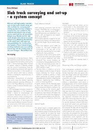
<strong>Safety</strong> <strong>measures</strong> <strong>for</strong> <strong>the</strong><br />
<strong>Wolfsgruben</strong> <strong>tunnel</strong><br />
Integrated track design in <strong>tunnel</strong>s with special reference to<br />
safety considerations<br />
In <strong>the</strong> wake of recent disasters due to<br />
fires in <strong>tunnel</strong>s, safety in <strong>tunnel</strong>s is a<br />
highly topical issue.The new<br />
<strong>Wolfsgruben</strong> <strong>tunnel</strong> in St.Anton am<br />
Arlberg has been designed so as to<br />
allow existing local firefighting vehicles<br />
direct access along <strong>the</strong> railway <strong>tunnel</strong>.<br />
In this context, <strong>the</strong> article describes<br />
<strong>the</strong> safety and civil engineering <strong>measures</strong><br />
in <strong>the</strong> <strong>Wolfsgruben</strong> <strong>tunnel</strong>.<br />
The 60 km long, single-track mountain railway<br />
over <strong>the</strong> Arlberg range was opened to<br />
traffic in 1884. Only <strong>the</strong> 10 km Arlberg tunnnel<br />
between St. Anton and Langen am<br />
Arlberg was constructed as a double-track<br />
section from <strong>the</strong> beginning. Due to <strong>the</strong><br />
increasing volume of traffic, it was finally<br />
decided about 15 years ago to increase <strong>the</strong><br />
The authors<br />
Dipl.-Ing. Dr. Hans Wehr, Austrian Federal Railways,<br />
Planning/Engineering department, Arlberg line<br />
upgrade Project Manager, Dipl.-Ing. Karl Schmid,<br />
Austrian Federal Railways, Arlberg line upgrade<br />
assistant Project Manager, Dipl.-Ing. Peter Ablinger,<br />
ibt <strong>Bahntechnik</strong> - Innovation Beratung Technologie<br />
(Railway Technology Consultancy)<br />
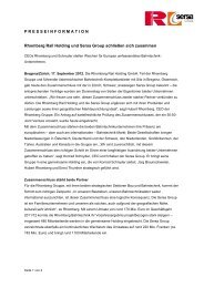
Abb.1: Betonzug im Arbeitseinsatz für das zweite Gleis<br />
capacity of <strong>the</strong> Arlberg line. This was to be<br />
achieved mainly by extending <strong>the</strong> doubletrack<br />
section on both sides of <strong>the</strong> Arlberg<br />
range, in <strong>the</strong> Stanzer and Kloster valley sections.<br />
Thanks to <strong>the</strong> double-track upgrade<br />
between Langen and Klösterle on <strong>the</strong><br />
Vorarlberg side, as well as <strong>the</strong> relocation of<br />
St. Anton station and an adjacent section of<br />
line totalling 4 km, and in conjunction with<br />
already upgraded sections in <strong>the</strong> Stanzer<br />
valley, a 23 km double-track section has now<br />
been created, representing more than one<br />
third of <strong>the</strong> total length of <strong>the</strong> Arlberg line.<br />
Both upgraded sections mentioned include<br />
<strong>the</strong> construction of new double-track tunnnels:<br />
<strong>the</strong> 1800 m <strong>Wolfsgruben</strong> <strong>tunnel</strong> on <strong>the</strong><br />
Tyrol side and <strong>the</strong> 2400 m Blisadona <strong>tunnel</strong><br />
on <strong>the</strong> Vorarlberg side. St. Anton and Langen<br />
am Arlberg stations respectively lie between<br />
<strong>the</strong>se new <strong>tunnel</strong>s and <strong>the</strong> Arlberg <strong>tunnel</strong><br />
(see Figs. 1 and 2).<br />
The close juxtaposition of <strong>the</strong>se <strong>tunnel</strong>s,<br />
especially taken toge<strong>the</strong>r with <strong>the</strong> recent fire<br />
disasters in <strong>the</strong> Mont Blanc and <strong>the</strong> Tauern<br />
road <strong>tunnel</strong>s which have strongly influenced<br />
public opinion, and with <strong>the</strong> great public<br />
interest in <strong>the</strong> 2001 alpine skiing world cup<br />
competition which took place immediately<br />
after <strong>the</strong> opening of <strong>the</strong> <strong>Wolfsgruben</strong> <strong>tunnel</strong>,<br />
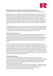
Fig. 1: Schematic map<br />
of <strong>the</strong> Arlberg line<br />
from Landeck to<br />
Bludenz<br />
Fig. 2: Overview of <strong>the</strong><br />
<strong>Wolfsgruben</strong> - Arlberg<br />
- Blisadona chain of<br />
<strong>tunnel</strong>s<br />
led <strong>the</strong> Austrian Federal Railways to give<br />
special attention to safety aspects of <strong>the</strong><br />
<strong>Wolfsgruben</strong> <strong>tunnel</strong>.<br />
In this context, <strong>the</strong> following aspects were<br />
taken into account:<br />
<strong>Safety</strong> policies of railway companies and<br />
rescue services,<br />
Definition of a realistic accident scenario,<br />
Resulting planning in terms of safety <strong>measures</strong>,<br />
based on self-rescue by passengers<br />
as well as adequate access <strong>for</strong> rescue services,<br />
Evaluation of <strong>the</strong> planned <strong>measures</strong> in<br />
order to ensure <strong>the</strong>ir compatibility, taking<br />
into account <strong>the</strong> whole chain of <strong>tunnel</strong>s.<br />
The safety philosophies of railway companies<br />
and fire services are fundamentally diffferent.<br />
It is <strong>the</strong> purpose of all railway safety<br />
installations to prevent unusual incidents. All<br />
safety installations operate in accordance<br />
with <strong>the</strong> "fail-safe" principle. The basic safety<br />
philosophy of railways is to take appropriate<br />
<strong>measures</strong> in order to avoid accidents.<br />
By contrast, fire brigades and rescue organisations<br />
set out from <strong>the</strong> assumption that an<br />
accident or a fire has occurred. They see<br />
<strong>the</strong>mselves as lifesavers and rescuers and as<br />
controllers and extinguishers of fires. Their<br />
contribution to risk reduction is limited to<br />
minimising <strong>the</strong> effects of an incident.<br />
These differing perspectives complement<br />
each o<strong>the</strong>r very well. However, because <strong>the</strong><br />
emergency services have no responsibility<br />
<strong>for</strong> <strong>the</strong> cost of an infrastructure project,<br />
<strong>the</strong>re is a risk of excessive investment in<br />
safety and of insufficient compatibility between<br />
preventive <strong>measures</strong> and <strong>measures</strong> to<br />
reduce <strong>the</strong> effects of incidents.<br />
The basis of <strong>tunnel</strong> safety planning has thus<br />
always been <strong>the</strong> extremely unlikely scenario<br />
of a passenger train being stuck in <strong>the</strong> tunnnel<br />
and <strong>the</strong>n catching fire. A comprehensive<br />
package of <strong>measures</strong> has been developed to<br />
deal with this scenario, with a view to <strong>the</strong>ir<br />
applicability also to o<strong>the</strong>r less spectacular<br />
accident scenarios.<br />
As indicated in reports on <strong>tunnel</strong> fires and<br />
confirmed by <strong>tunnel</strong> fire tests in Norway in<br />
1992 in <strong>the</strong> course of <strong>the</strong> EUREKA project<br />
[1], [2], about 15 minutes elapse between<br />
<strong>the</strong> outbreak of a fire and <strong>the</strong> <strong>tunnel</strong> being<br />
entirely filled with smoke at <strong>the</strong> source of<br />
1<br />
Published in EI - Eisenbahningenieur (52) 9/2001 site 32-37<br />
<strong>Rhomberg</strong> Bau AG<br />
A-6900 Bregenz<br />
Tel.: +43 (5574) 403 0<br />
Fax : +43 (5574) 403 249<br />
hubert.rhomberg@rhombergbau.at<br />
www.bahntechnik.com
SAFETY IN TUNNEL<br />
RHOMBERG<br />
BAHNTECHNIK<br />
<strong>the</strong> fire. The most effective action is<br />
<strong>the</strong>re<strong>for</strong>e <strong>the</strong> rapid evacuation of <strong>the</strong><br />
stranded train.<br />
<strong>Safety</strong> approach <strong>for</strong> <strong>the</strong><br />
<strong>Wolfsgruben</strong> <strong>tunnel</strong><br />
station to <strong>the</strong> <strong>tunnel</strong> mouth as well as rapid<br />
access within <strong>the</strong> <strong>tunnel</strong>.<br />
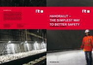
In addition, <strong>for</strong> <strong>the</strong> first time in Austria, <strong>the</strong><br />
track in <strong>the</strong> <strong>Wolfsgruben</strong> <strong>tunnel</strong> has been<br />
designed to enable drive-in access <strong>for</strong> road<br />
vehicles, as shown in Fig. 4.<br />
The technical solutions <strong>for</strong> this slab track<br />
construction to enable access by<br />
road vehicles, toge<strong>the</strong>r with <strong>the</strong> technical<br />
and organisational precautions taken in<br />
order to segregate <strong>the</strong> emergency operation<br />
of rescue teams on <strong>the</strong> track from normal<br />
track operations, are described in <strong>the</strong><br />
The Zammer <strong>tunnel</strong><br />
In 1992, in <strong>the</strong> course of <strong>the</strong> project approval<br />
procedure <strong>for</strong> <strong>the</strong> Zammer <strong>tunnel</strong><br />
(Innsbruck - Landeck line), only walkable<br />
cesses with a minimum width of 1.20 m,<br />
emergency niches with a maximum spacing<br />
of 50 m as well as a continuous handrail<br />
were specified. Radiating cable equipment<br />
offered new opportunities <strong>for</strong> emergency<br />
radio applications. Fire services were expected<br />
to be equipped with road-rail vehicles.<br />
Because <strong>the</strong> operating licence was not<br />
Fig. 3: Emergency access at <strong>the</strong> western portal<br />
Fig. 4: Accessing <strong>the</strong> <strong>tunnel</strong> during a fire service exercise<br />
Construction details have <strong>the</strong>re<strong>for</strong>e been<br />
designed so as to give passengers a good<br />
chance of escape from <strong>the</strong> dangerous part<br />
of <strong>the</strong> <strong>tunnel</strong> within 15 minutes, thus<br />
enabling <strong>the</strong>ir self-rescue in good time.<br />
Wide "cess" walkways, lighting <strong>for</strong> orientation<br />
purposes, hand rails, clear signs marking<br />
<strong>the</strong> escape route and an exit into <strong>the</strong> open<br />
air provided by a lateral gallery have been<br />
incorporated in <strong>the</strong> original construction,<br />
representing <strong>the</strong> most effective <strong>measures</strong> to<br />
facilitate self-rescue. Thanks to <strong>the</strong> lateral<br />
service <strong>tunnel</strong>, <strong>the</strong> distance between safe<br />
areas never exceeds 900 m, thus a maximum<br />
walking distance of 450 m is required <strong>for</strong><br />
passengers to reach safety.<br />
Lighted rescue areas, which can be easily<br />
accessed by road vehicles, are situated at <strong>the</strong><br />
<strong>tunnel</strong> mouths.Assistance by <strong>the</strong> fire services<br />
is greatly facilitated by speedy alarm routines<br />
and good organisation. Fully equipped rescue<br />
teams are expected to be able to reach<br />
<strong>the</strong> <strong>tunnel</strong> portals within 10 minutes. In<br />
order to exploit this per<strong>for</strong>mance to <strong>the</strong> full,<br />
<strong>the</strong> aim of fur<strong>the</strong>r planning was to ensure<br />
<strong>the</strong> most unobstructed possible access<br />
within <strong>the</strong> <strong>Wolfsgruben</strong> <strong>tunnel</strong>, and <strong>the</strong><br />
incorporation of a permanent water supply<br />
to fire hydrants so as to allow effective fire<br />
brigade operations.<br />
Also taking into account <strong>the</strong> needs of <strong>the</strong><br />
Arlberg <strong>tunnel</strong>, <strong>the</strong> St. Anton fire brigade is<br />
equipped with a combined road/rail fire<br />
engine <strong>for</strong> operation in <strong>tunnel</strong>s, thus<br />
ensuring a quick approach from <strong>the</strong> fire<br />
following sections.<br />
Technical and organisational<br />
precautions<br />
In recent years, slab track has been increasingly<br />
adopted by Austrian Federal Railways,<br />
primarily to ensure stable track alignment<br />
and to minimise maintenance costs. On <strong>the</strong><br />
Austrian Federal Railways, slab track is used<br />
mainly in new <strong>tunnel</strong>s.<br />
However, <strong>the</strong> smooth concrete surfaces in<br />
<strong>the</strong> <strong>tunnel</strong> and <strong>the</strong> lack of sound deadening<br />
on <strong>the</strong> undersides of carriages led to<br />
increasing complaints from passengers.<br />
Sleeping car passengers have found this<br />
noise nuisance particularly disturbing.<br />
Extensive research has led to <strong>the</strong> development<br />
of acoustic panels to reduce noise<br />
reflection from <strong>the</strong> smooth concrete surface<br />
to <strong>the</strong> undersides of carriages.Tunnels which<br />
had already been completed have been<br />
upgraded with <strong>the</strong>se acoustic panels.<br />
Because of <strong>the</strong> construction of numerous<br />
<strong>tunnel</strong>s on new lines and not least as a result<br />
of recent <strong>tunnel</strong> disasters, rail <strong>tunnel</strong> safety<br />
has also been subjected to intensive research,<br />
and solutions have been developed to<br />
increase <strong>the</strong> level of safety.<br />
issued with <strong>the</strong> legal construction permit<br />
required by railway regulations, joint <strong>measures</strong><br />
have been established in coordination<br />
with local authorities and <strong>the</strong>ir experts and<br />
in close contact with <strong>the</strong> fire services, in<br />
order to upgrade <strong>the</strong> Zammer <strong>tunnel</strong> in<br />
terms of safety. In 2000 <strong>the</strong>se <strong>measures</strong><br />
finally led to <strong>the</strong> successful completion of <strong>the</strong><br />
operating licensing procedure required by<br />
railway regulations.<br />
The additional <strong>measures</strong> include a fire<br />
hydrant duct mounted on <strong>the</strong> lower part of<br />
<strong>the</strong> right hand side wall of <strong>the</strong> <strong>tunnel</strong> as well<br />
as a reservoir with a volume of 108 m3 at<br />
<strong>the</strong> eastern portal, orientation lighting and<br />
escape route signs installed in <strong>the</strong> <strong>tunnel</strong>, rescue<br />
areas and communications facilities<br />
(emergency operations rooms) provided at<br />
<strong>the</strong> <strong>tunnel</strong> mouths, and finally a re-railing<br />
device <strong>for</strong> <strong>the</strong> road-rail fire engine as well as<br />
an electrically locked entry barrier.<br />
<strong>Wolfsgruben</strong> <strong>tunnel</strong><br />
For <strong>the</strong> <strong>Wolfsgruben</strong> <strong>tunnel</strong>, all <strong>the</strong>se <strong>measures</strong><br />
were already incorporated during <strong>the</strong><br />
project planning stage (see Fig. 5):<br />
Escape gallery (L = 180 m): Due to <strong>the</strong><br />
time-critical construction schedule <strong>for</strong> its<br />
2<br />
Published in EI - Eisenbahningenieur (52) 9/2001 site 32-37<br />
<strong>Rhomberg</strong> Bau AG<br />
A-6900 Bregenz<br />
Tel.: +43 (5574) 403 0<br />
Fax : +43 (5574) 403 249<br />
hubert.rhomberg@rhombergbau.at<br />
www.bahntechnik.com
SAFETY IN TUNNEL<br />
RHOMBERG<br />
BAHNTECHNIK<br />
implementation, <strong>the</strong> <strong>Wolfsgruben</strong> <strong>tunnel</strong><br />
had to be driven via a lateral access galllery.Today,<br />
this lateral gallery is available <strong>for</strong><br />
use as an escape <strong>tunnel</strong>, joining <strong>the</strong> main<br />
<strong>tunnel</strong> at approximately mid-length.<br />
Thanks to <strong>the</strong> bigger cross section required<br />
by <strong>the</strong> construction process, it is posssible<br />
to provide emergency vehicle access<br />
to <strong>the</strong> main <strong>tunnel</strong> via <strong>the</strong> escape gallery.<br />
Fire door (25 m2): A smoke-proof door<br />
was constructed in <strong>the</strong> area of <strong>the</strong> intersection<br />
of <strong>the</strong> main <strong>tunnel</strong> and <strong>the</strong> escape<br />
gallery, enabling a safe stay of at least 90<br />
minutes. Thus, passengers have to walk<br />
450 m at <strong>the</strong> most in order to reach safety.<br />
The construction of fire doors is especially<br />
important in alpine regions, because<br />
<strong>the</strong> distance from <strong>the</strong> main <strong>tunnel</strong> into <strong>the</strong><br />
open air can significantly leng<strong>the</strong>n <strong>the</strong><br />
escape route, as shown, <strong>for</strong> example, by<br />
<strong>the</strong> Blisadona <strong>tunnel</strong> in Langen with its<br />
420 m long escape gallery.<br />
Emergency exit doors: The emergency<br />
exits into <strong>the</strong> escape gallery and in <strong>the</strong><br />
area of <strong>the</strong> fire door are equipped with<br />
"panic locks" allowing opening in <strong>the</strong> escape<br />
direction. Opening of track-side doors<br />
from outside is prevented by means of an<br />
electric lock and is only possible after consultation<br />
with and release by <strong>the</strong> emergency<br />
operation centre.<br />
Communications rooms: Communications<br />
rooms fitted out with telephone,<br />
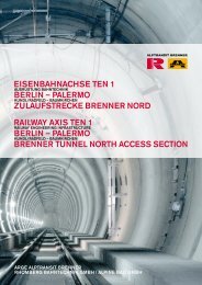
Fig.: 5: <strong>Safety</strong> scheme<br />
<strong>for</strong> <strong>the</strong> <strong>Wolfsgruben</strong><br />
<strong>tunnel</strong><br />
Fig. 6: Eastern portal<br />
with emergency/rescue<br />
area and barriers<br />
to <strong>the</strong> track area<br />
fax and emergency radio are situated near<br />
each <strong>tunnel</strong> portal and emergency exit in<br />
order to enable optimum two-way<br />
communication with rescue teams. The<br />
emergency operations centre is co-located<br />
with <strong>the</strong> train operations control centre<br />
in St. Anton am Arlberg station.<br />
Rescue area (1500 m2): Paved rescue<br />
areas covering about 1500 m2, equipped<br />
with sufficient lighting as well as appropriate<br />
barriers to keep <strong>the</strong>m permanently<br />
clear of obstructions, face each of <strong>the</strong><br />
communications/control rooms. These<br />
rescue areas provide space <strong>for</strong> emergency<br />
vehicles and <strong>for</strong> tents <strong>for</strong> first aid to <strong>the</strong><br />
injured. In <strong>the</strong> winter<br />
months, <strong>the</strong>se<br />
areas must also be<br />
kept clear of<br />
snow. If at all posssible,<br />
helicopter<br />
landing facilities<br />
should be available<br />
in <strong>the</strong> immediate<br />
vicinity (see<br />
Fig. 6).<br />
Water duct <strong>for</strong><br />
hydrants: Due to<br />
<strong>the</strong> delayed decision<br />
about <strong>the</strong><br />
need <strong>for</strong> this, <strong>the</strong><br />
firefighting water<br />
pipe has been<br />
installed at a height of about 4.2 m on <strong>the</strong><br />
lower right wall of <strong>the</strong> <strong>tunnel</strong>, as shown in<br />
Fig. 7.The hydrant duct consists of insulated<br />
pipes which are additionally equipped<br />
with a heater band. Hydrants are placed in<br />
<strong>the</strong> emergency niches, with a maximum<br />
spacing of 150 m.<br />
Moreover, <strong>the</strong> hydrant system has been designed<br />
with shutoff units every 450 m. The<br />
hydrant duct is a wet pipe, i.e. it is permanently<br />
filled, with a pressure of at least 7 bar.<br />
In accordance with a joint decision, <strong>the</strong> pipe,<br />
which is fed from one direction only, must<br />
provide water at a rate of 20 litres/second<br />
<strong>for</strong> a period of 90 minutes. A reservoir with<br />
a volume of 108 m3 as well as an additional<br />
deep well have <strong>the</strong>re<strong>for</strong>e been set up in <strong>the</strong><br />
feeding area. In order to achieve maximum<br />
availability of <strong>the</strong> water supply with its electrically<br />
operated pumps, an emergency<br />
power supply with its own generators was<br />
designed. On future new <strong>tunnel</strong> projects, <strong>the</strong><br />
water supply to fire hydrants will be incorporated<br />
beneath <strong>the</strong> cesses and water<br />
reservoirs will be provided at both <strong>tunnel</strong><br />
portals. This should prevent any damage in<br />
case of future disasters.<br />
Emergency niches: Emergency niches<br />
have been incorporated on both sides<br />
throughout <strong>the</strong> <strong>tunnel</strong>, with a maximum<br />
spacing of 50 m. The niches with fire<br />
hydrants are also equipped with electric<br />
power outlets (Fig. 7).<br />
Orientation lighting: Orientation lighting<br />
has been fitted above every emergency<br />
niche. Thanks to illuminated push<br />
button switches, anybody in <strong>the</strong> <strong>tunnel</strong> can<br />
switch it on. However, lighting can only be<br />
switched off from <strong>the</strong> emergency control<br />
centre.<br />
Cesses:The cess walkway is 1.30 m wide,<br />
generally arranged at <strong>the</strong> same level as <strong>the</strong><br />
top of <strong>the</strong> rails, and must be kept free<br />
from any fur<strong>the</strong>r installation which may<br />
cause obstruction.<br />
Drivability: To enable road vehicles to<br />
Fig. 7: Emergency niche with fire hydrant and orientation lighting<br />
3<br />
Published in EI - Eisenbahningenieur (52) 9/2001 site 32-37<br />
<strong>Rhomberg</strong> Bau AG<br />
A-6900 Bregenz<br />
Tel.: +43 (5574) 403 0<br />
Fax : +43 (5574) 403 249<br />
hubert.rhomberg@rhombergbau.at<br />
www.bahntechnik.com
SAFETY IN TUNNEL<br />
RHOMBERG<br />
BAHNTECHNIK<br />
Fig. 10: GRP grid at a switch<br />
Fig. 8: Drivability with concrete to top-of-sleeper<br />
level<br />
Fig. 9: Drivability with concrete to top-of-rail<br />
level<br />
4<br />
access <strong>the</strong> <strong>tunnel</strong> <strong>the</strong> acoustic panels have<br />
been streng<strong>the</strong>ned in accordance with<br />
static requirements. Thanks to <strong>the</strong> rail<br />
height of 19 cm, this did not cause any<br />
problem. However <strong>the</strong> design of <strong>the</strong><br />
sound-absorbing surfaces is critical; while<br />
damage cannot be excluded in a disaster<br />
situation, during emergency service training<br />
care should be taken to protect<br />
<strong>the</strong>m.<br />
Between <strong>the</strong> rails (<strong>the</strong> four-foot way), <strong>the</strong><br />
rolling surface <strong>for</strong> road vehicles is provided<br />
by means of drivable absorption panels,<br />
while in <strong>the</strong> six-foot way (between tracks),<br />
drivability has been ensured by filling with filtering<br />
concrete up to sleeper-top level. In<br />
<strong>the</strong> <strong>tunnel</strong> portal areas as well as in <strong>the</strong> area<br />
of <strong>the</strong> intersection with <strong>the</strong> escape gallery,<br />
<strong>the</strong> six-foot way has been filled fur<strong>the</strong>r, up to<br />
top-of-rail level, to enable those escaping to<br />
reach safety without obstacles.<br />
This also makes it easier <strong>for</strong> emergency vehicles<br />
to get onto <strong>the</strong> tracks or to turn round<br />
at specific places in <strong>the</strong> <strong>tunnel</strong>.Training exercises<br />
have shown that filling with concrete up<br />
to top-of-rail level offers significant advantages<br />
to emergency vehicles needing to pass<br />
each o<strong>the</strong>r in <strong>the</strong> <strong>tunnel</strong>.<br />
In <strong>the</strong> next <strong>tunnel</strong>, in Langen am Arlberg (<strong>the</strong><br />
Blisadona <strong>tunnel</strong>), filling will be to top-of-rail<br />
level throughout its length. As a result of<br />
having <strong>the</strong> same level over <strong>the</strong> whole cross<br />
section of <strong>the</strong> <strong>tunnel</strong>, <strong>the</strong> possibility of emergency<br />
vehicles driving on <strong>the</strong> cess walkways<br />
cannot be excluded, so <strong>the</strong> cable ducts situated<br />
in this area must also be equipped with<br />
drivable covers (Figs. 8 and 9).<br />
In <strong>the</strong> vicinity of switches, because of <strong>the</strong><br />
continuously varying distance between <strong>the</strong><br />
individual running rails, special constructions<br />
in <strong>the</strong> <strong>for</strong>m of gratings had to be used. Up to<br />
170 different components per switch had to<br />
be produced <strong>for</strong> this purpose. Moreover, <strong>for</strong><br />
safety reasons, <strong>the</strong>se components could not<br />
exceed 30 kg in weight, in order to enable<br />
one person to handle <strong>the</strong>m in case of failure.<br />
For switch diagnostic systems, which are<br />
particularly sensitive to magnetic disturbance,<br />
<strong>the</strong> grids had to be made of glassfibre-rein<strong>for</strong>ced<br />
plastic (GRP) (Fig. 10).<br />
Wherever escape routes cross <strong>the</strong> track, <strong>the</strong><br />
remaining 18 cm gaps between <strong>the</strong> running<br />
rail and <strong>the</strong> drivable acoustic panel on <strong>the</strong><br />
one hand, and <strong>the</strong> cess walkway on <strong>the</strong><br />
o<strong>the</strong>r hand, have been filled with plastic gap<br />
fillers (Fig. 11). In <strong>the</strong> future, this gap will be<br />
reduced to 13 cm, thus enabling <strong>the</strong>se plastic<br />
components to be dispensed with.<br />
Thanks to <strong>the</strong> drivability of <strong>the</strong> whole tunnnel<br />
area, after intensive negotiations <strong>the</strong> local<br />
fire services agreed that <strong>the</strong> railway authority<br />
could rely on <strong>the</strong>ir existing infrastructure.<br />
Thus, in contrast with <strong>the</strong> purchase and<br />
maintenance of a dedicated train <strong>for</strong> <strong>tunnel</strong><br />
emergencies, including provision of <strong>the</strong><br />
necessary staff, only small adaptations have<br />
been necessary to <strong>the</strong> equipment of <strong>the</strong><br />
local fire services.<br />
Construction design<br />
Published in EI - Eisenbahningenieur (52) 9/2001 site 32-37<br />
Drivability on prefabricated slab track<br />
The track design in <strong>the</strong> <strong>tunnel</strong>, enabling both<br />
drivability and noise absorption, is a special<br />
feature. Backed-up by comprehensive tests<br />
and research, this system, which is based on<br />
<strong>the</strong> BAFS drivable sound-absorbing guard<br />
rail system, approved in Germany <strong>for</strong> operational<br />
testing and already used on <strong>the</strong> new<br />
Hanover - Berlin line, and on sound-absorbing<br />
track covers, has now been practically<br />
implemented in <strong>the</strong> <strong>Wolfsgruben</strong> <strong>tunnel</strong> in<br />
cooperation with <strong>the</strong> Rieder and <strong>the</strong><br />
<strong>Rhomberg</strong> Bau companies.<br />
Figs. 12 and 13 show two cases of loading of<br />
<strong>the</strong> sound-absorbing track covers with a<br />
wheel load of 85 kN. Even with <strong>the</strong> loading<br />
shown in Fig. 13, which rarely occurs in practice,<br />
no damage has been observed. Only<br />
steering movements under full wheel load<br />
produce some damage to <strong>the</strong> edges. In <strong>the</strong><br />
access ramp areas, <strong>the</strong>se edges have <strong>the</strong>re<strong>for</strong>e<br />
been additionally protected by means<br />
of steel angles. The sound-absorbing track<br />
covers are manufactured in two separate<br />
<strong>Rhomberg</strong> Bau AG<br />
A-6900 Bregenz<br />
Fig. 11: Access area with plastic gap fillers<br />
Fig. 12: Loading of <strong>the</strong> track cover with 85 kN<br />
Fig. 13: Atypical loading of 85 kN during <strong>the</strong><br />
test<br />
Fig. 14: Design and placement of <strong>the</strong> soundabsorbing<br />
drivable track cover<br />
Tel.: +43 (5574) 403 0<br />
Fax : +43 (5574) 403 249<br />
hubert.rhomberg@rhombergbau.at<br />
www.bahntechnik.com
SAFETY IN TUNNEL<br />
RHOMBERG<br />
BAHNTECHNIK<br />
Fig. 15: Longitudinal section of <strong>the</strong> drivable cover panel (decoupled from<br />
<strong>the</strong> sleepers)<br />
Fig. 16: Transition from elastically supported individual sleepers to slab<br />
track with prefabricated components<br />
layers with supporting steel-rein<strong>for</strong>ced concrete<br />
plus absorbent porous concrete, and<br />
are <strong>the</strong>n laid elastically on <strong>the</strong> prefabricated<br />
track slabs using strips at <strong>the</strong> outer side of<br />
<strong>the</strong> plate, as shown in Fig. 14. These plates<br />
are bolted onto <strong>the</strong> substructure in order to<br />
prevent <strong>the</strong>m from shifting due to vibrations<br />
caused by <strong>the</strong> passage of trains.<br />
Drivability on elastically supported<br />
monobloc sleepers<br />
In <strong>the</strong> sections with <strong>the</strong> six drivable switches<br />
as well as in <strong>the</strong> intermediate tracks, a slab<br />
track design with monobloc sleepers elastically<br />
supported in rubber shoes has been<br />
chosen and implemented. In order not to<br />
alter <strong>the</strong> elastic properties of track and switches,<br />
all drivable parts of <strong>the</strong> construction<br />
design had to be decoupled from <strong>the</strong> sleepers.<br />
Fig. 15 shows <strong>the</strong> longitudinal section of<br />
this design. In <strong>the</strong> spaces between sleepers,<br />
mouldings are placed on iron pins previously<br />
set out in lean-mix concrete, are <strong>the</strong>n<br />
adjusted and grouted with concrete. The<br />
sound-absorbing panels are <strong>the</strong> laid on <strong>the</strong>se<br />
mouldings and bolted in place at <strong>the</strong>ir joints<br />
with <strong>the</strong> substructure.<br />
External track covers<br />
Areas outside <strong>the</strong> track are covered with<br />
prefabricated components up to a distance<br />
of 18 cm from <strong>the</strong> outer edge of <strong>the</strong> rail,<br />
thus ensuring that <strong>the</strong> elastically supported<br />
sleepers are entirely decoupled.<br />
Summary<br />
In spite of <strong>the</strong> extremely short construction<br />
schedule, numerous details used <strong>for</strong> <strong>the</strong> first<br />
time in this project were developed and efficiently<br />
implemented in <strong>the</strong> course of construction,<br />
thanks to <strong>the</strong> close cooperation<br />
between <strong>the</strong> ÖBB project management, <strong>the</strong><br />
project design engineers and <strong>the</strong> railway<br />
construction contractors under <strong>the</strong> technical<br />
direction of <strong>Rhomberg</strong> Bau GmbH.<br />
The integrated approach of all those involved<br />
to meeting <strong>the</strong> very wide variety of<br />
requirements, toge<strong>the</strong>r with <strong>the</strong>ir comprehensive<br />
technical and organisational solutions,<br />
enabled timely completion ready <strong>for</strong><br />
<strong>the</strong> skiing world cup in St. Anton in 2001.<br />
Tunnelsicherheitsmaßnahmen<br />
für den <strong>Wolfsgruben</strong><strong>tunnel</strong><br />
Auf Grund der letzten Katastrophen bei<br />
Tunnelbränden ist das Thema Tunnelsicherheit<br />
hoch aktuell. In St.Anton am Arlberg wurde der<br />
neue Wolfgruben<strong>tunnel</strong> derart ausgerüstet, dass<br />
er als Bahn<strong>tunnel</strong> mit den vorhandenen<br />
Einsatzfahrzeugen der örtlichen Feuerwehren<br />
direkt befahren werden kann. In diesem<br />
Zusammenhang beschreibt der vorliegende<br />
Artikel die sicherheits- und bautechnischen<br />
Maßnahmen im <strong>Wolfsgruben</strong><strong>tunnel</strong>.<br />
Mesures de sécurité pour le<br />
<strong>tunnel</strong> du <strong>Wolfsgruben</strong><br />
Compte tenu des dernières catastrophes dues à<br />
des incendies dans des <strong>tunnel</strong>s, le thème de la<br />
sécurité est à l’ordre du jour. A St. Anton am<br />
Arlberg, le nouveau <strong>tunnel</strong> du <strong>Wolfsgruben</strong> a été<br />
équipé de facon à pouvoir être emprunté directement<br />
par les véhicles actuels du service local<br />
des pompiers.<br />
5<br />
Published in EI - Eisenbahningenieur (52) 9/2001 site 32-37<br />
<strong>Rhomberg</strong> Bau AG<br />
A-6900 Bregenz<br />
Tel.: +43 (5574) 403 0<br />
Fax : +43 (5574) 403 249<br />
hubert.rhomberg@rhombergbau.at<br />
www.bahntechnik.com