Slab track surveying and set-up - Rhomberg Bahntechnik
Slab track surveying and set-up - Rhomberg Bahntechnik
Slab track surveying and set-up - Rhomberg Bahntechnik

You also want an ePaper? Increase the reach of your titles
YUMPU automatically turns print PDFs into web optimized ePapers that Google loves.
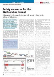
SLAB TRACK<br />
RHOMBERG<br />
BAHNTECHNIK<br />
Fig. 1: Track reference network scheme<br />
Fig. 2a: Clamping on top of the side wall of the<br />
concrete trough<br />
Fig. 2b: Special tripod<br />
with total station<br />
Fig. 2c: Special tripod<br />
with reflector<br />
curvature are used as transition curves.<br />
An important advantage of the procedure is<br />
that the measuring trolley does not have to<br />
follow any particular pattern of points but<br />
can be positioned at any required point on<br />
the <strong>track</strong>.<br />
Values needed to adjust the <strong>track</strong> such as left<br />
<strong>and</strong> right rail heights as well as lateral position<br />
correction are displayed on screen at a large<br />
scale <strong>and</strong> to 0.1 mm accuracy. Moreover, the<br />
km chainage ("km station"), the measured <strong>and</strong><br />
the theoretical s<strong>up</strong>erelevation (cant) as well<br />
as the <strong>track</strong> gauge values are available in any<br />
individual point.<br />
Depending on the quality required <strong>and</strong> the<br />
available timescale, the values s<strong>up</strong>plied to the<br />
measuring trolley will be <strong>up</strong>dated at intervals<br />
of about two seconds in <strong>track</strong>ing mode <strong>and</strong><br />
five seconds in precision mode. The operation<br />
team can immediately observe the position<br />
<strong>and</strong> height adjustment of the <strong>track</strong> within<br />
the 0.1 mm accuracy range.<br />
Adjusting <strong>and</strong> fixing system<br />
Starting from the st<strong>and</strong>ardised manufacturing<br />
procedures in use <strong>up</strong> to 1998, especially on<br />
the Hanover - Berlin high speed line, the problems<br />
are now described in detail <strong>and</strong> the<br />
new solutions are explained.<br />
Fig. 3: Hergie system<br />
measuring trolley<br />
Initial situation with the RHEDA<br />
system<br />
Up to now, monobloc sleepers have been<br />
used primarily with the RHEDA system.<br />
Horizontal <strong>and</strong> vertical screw spindles are<br />
incorporated in every second sleeper in<br />
order to adjust the <strong>track</strong> height. Because<br />
vertical spindles do not provide any lateral<br />
fixing, <strong>track</strong> adjustment by using this method<br />
can only be ensured by bracing the <strong>track</strong><br />
assembly against the side walls of the<br />
concrete trough.The principle of vertical <strong>and</strong><br />
horizontal adjustment <strong>and</strong> fixing of position<br />
of the <strong>track</strong> by means of the vertical spindles<br />
<strong>and</strong> the horizontal screw embedded in<br />
alternate sleepers are shown in the cross section<br />
(Fig. 4a) <strong>and</strong> the s<strong>up</strong>port scheme<br />
(Fig. 4b).<br />
Fig. 5a illustrates the s<strong>up</strong>port <strong>and</strong> clamping of<br />
the vertical spindles. It is easy to see that an<br />
accurate horizontal adjustment based on<br />
these s<strong>up</strong>ports is hardly possible. If lateral forces<br />
are applied, a moment will build <strong>up</strong> in the<br />
vertical spindle which will be released spontaneously<br />
when static friction is exceeded,<br />
thus preventing continuous horizontal<br />
adjustment of the <strong>track</strong>.<br />
Because of the highly elastic reaction of the<br />
whole system, the lateral screws shown in Fig.<br />
5b need to be used in order to brace the<br />
<strong>track</strong> assembly against the concrete trough<br />
on both sides of the sleeper.This implies that<br />
two screws must always be used for the lateral<br />
adjustment of the <strong>track</strong>. One detail which<br />
has not received much attention <strong>up</strong> to now is<br />
the free play of the rail within its fastening.<br />
The manufacturing tolerances of sleepers,<br />
baseplates <strong>and</strong> of the rail itself require an average<br />
clearance of 1 mm. In case of accidental<br />
unfavourable addition of individual<br />
tolerances, this clearance may increase to <strong>up</strong><br />
to 2 mm. This aspect is especially important<br />
when replacing rails at the end of their life or<br />
pulling them back after welding.<br />
Track alignment by means of the abovementioned<br />
vertical <strong>and</strong> horizontal spindles<br />
requires several iterative adjustments<br />
because the elastic mounting <strong>and</strong> the<br />
resulting residual stress within the <strong>track</strong> will<br />
always affect previously adjusted <strong>track</strong> as the<br />
work proceeds.<br />
Varying rail lengths caused by changes of rail<br />
temperature lead to additional problems<br />
which cannot be managed with this<br />
adjustment system. It happened several times<br />
that with significant rail temperature<br />
differences (<strong>up</strong> to 40°C between day <strong>and</strong><br />
night) the already adjusted <strong>track</strong> builds <strong>up</strong><br />
high stresses which are released<br />
spontaneously when adhesive forces are<br />
exceeded.Thus a further adjustment, with all<br />
its disadvantages in terms of delaying other<br />
construction work, is required.<br />
2<br />
Veröffentlicht im EI - Eisenbahningenieur (52) 9/2001 Seite 15-21<br />
<strong>Rhomberg</strong> Bau AG<br />
A-6900 Bregenz<br />
Tel.: +43 (5574) 403 0<br />
Fax : +43 (5574) 403 249<br />
hubert.rhomberg@rhombergbau.at<br />
www.bahntechnik.com