Slab track surveying and set-up - Rhomberg Bahntechnik
Slab track surveying and set-up - Rhomberg Bahntechnik
Slab track surveying and set-up - Rhomberg Bahntechnik

Create successful ePaper yourself
Turn your PDF publications into a flip-book with our unique Google optimized e-Paper software.
Peter Ablinger<br />
SLAB TRACK<br />
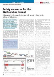
<strong>Slab</strong> <strong>track</strong> <strong>surveying</strong> <strong>and</strong> <strong>set</strong>-<strong>up</strong><br />
- a system concept<br />
RHOMBERG<br />
BAHNTECHNIK<br />
Efficient <strong>and</strong> high-quality manufacture<br />
of slab <strong>track</strong> entails using specific<br />
methods for <strong>surveying</strong> <strong>and</strong><br />
<strong>set</strong>ting <strong>up</strong> that function reliably in<br />
construction site conditions.The<br />
methods described in the article<br />
can be used both for all monolithic<br />
designs (e.g. Rheda) <strong>and</strong> for slab<br />
<strong>track</strong> designs with elastic-mounted<br />
sleepers (e.g. Bözberg, Euroblock);<br />
at the same time, they open <strong>up</strong><br />
new possibilities for construction<br />
site logistics.These industrial-type<br />
working methods were successfully<br />
used to lay 126 km of slab <strong>track</strong> on<br />
the new Cologne - Rhein/Main line.<br />
Surveying<br />
Surveying work on the new Hanover - Berlin<br />
high speed line proved that the behaviour of<br />
<strong>track</strong> displacement monitoring control points<br />
(GVP = Gleisvermarkungspunkte) mounted<br />
on catenary s<strong>up</strong>ports is relatively unstable<br />
over the course of construction. Given the<br />
tight manufacturing tolerances with regard to<br />
internal <strong>track</strong> accuracy, it is the unstable control<br />
point network which leads to extreme<br />
difficulty in meeting the required accuracy of<br />
<strong>track</strong> positioning.<br />
Independent measurements of individual<br />
<strong>track</strong> points using the arbitrary stationing<br />
method produced measuring differences of<br />
<strong>up</strong> to 5 mm.These differences occurred particularly<br />
in areas of transition between instrument<br />
stations.<br />
In 1999, the Stuttgart University Institute for<br />
Geodetic Applications in Civil Engineering<br />
(IAGB = Institut für Anwendungen der<br />
Geodäsie im Bauwesen) carried out a comprehensive<br />
analysis of basic <strong>surveying</strong> principles<br />
for slab <strong>track</strong> construction work. It was<br />
found in the course of this project that<br />
without special additional measures the existing<br />
control points (GVP) were scarcely adequate<br />
as a basis for slab <strong>track</strong> construction<br />
work.<br />
The author<br />
Dipl.-Ing. Dr. Peter Ablinger, ibt <strong>Bahntechnik</strong><br />
- Innovation Beratung Technologie,<br />
(Railway technology consultancy),<br />
Lambach (Austria)<br />
Track reference network<br />
While preparing construction work for the<br />
Cologne - Rhein/Main line, a <strong>surveying</strong> approach<br />
using <strong>track</strong> reference points (GRP =<br />
Gleisreferenzpunkte) was established in cooperation<br />
with, <strong>and</strong> based on the research<br />
results of, the IAGB [1].<br />
This <strong>surveying</strong> approach is based on its own<br />
reference point network with fixed points in<br />
the concrete troughs.This has several advantages:<br />
These <strong>track</strong> reference points (GRP) are<br />
formed by M12-type threaded pins<br />
incorporated in the side walls of the<br />
troughs, thus representing the most stable<br />
reference for <strong>track</strong> production;<br />
The position of the control points (GVP)<br />
varies over the whole construction process<br />
due to ground <strong>set</strong>tlement <strong>and</strong> other<br />
influences. They should therefore be<br />
considered as "changing fixed points".Thus,<br />
to keep the <strong>track</strong>-laying process free of<br />
these changes, the <strong>track</strong> reference point<br />
(GRP) network is used;<br />
The total station or reflector is <strong>set</strong> <strong>up</strong> at<br />
<strong>track</strong> reference points by means of special<br />
tripods following the forced centring<br />
method. In contrast to arbitrary or "free"<br />
station positioning, this system provides<br />
repeatable station positions, integrating the<br />
respective neighbouring <strong>track</strong> reference<br />
points as measuring stations.<br />
A specific network will be measured, based<br />
on these <strong>track</strong> reference points (GRP). The<br />
network adjustment scheme is outlined in Fig.<br />
1. When carrying out the network adjustment,<br />
the <strong>track</strong> reference points (GRP) are<br />
calculated as a rigid network with elastic links<br />
to the control points (GVP) thus resulting in<br />
the highest possible stability of the GRP-network<br />
used later on to adjust the actual <strong>track</strong><br />
position.<br />
Special tripods<br />
The special tripod is clamped against the<br />
screw bolt with the base plate. The tripod is<br />
then levelled by means of the ball joint whose<br />
centre is situated 40 mm above the lower<br />
edge of the s<strong>up</strong>port plate. This levelling process<br />
is carried out in two phases: first (coarsely)<br />
by means of a circular bubble <strong>and</strong> after<br />
that, by means of a precise spirit level or the<br />
relevant centring device of the total station.<br />
These special tripods have the following<br />
advantages:<br />
Every forward <strong>and</strong> back station can be<br />
incorporated in the measurement thus<br />
reducing the error in intermediate areas<br />
between pairs of instrument stations to a<br />
minimum.<br />
Thanks to the use of forced centring,<br />
coordinates of the instrument stations are<br />
known. Costly signalisation <strong>and</strong> pointing to<br />
6 - 8 control points (GVP) to fix the free<br />
stations can thus be avoided.<br />
The clamp arrangement ensures that the<br />
tripods are very well connected to the<br />
subsoil so that even short period vibrations<br />
caused by construction site traffic do<br />
not affect instrument station quality.<br />
Thanks to the stable connection to the<br />
ground, acceleration <strong>and</strong> deceleration forces<br />
occurring with motorised total stations<br />
can be absorbed.<br />
Figs. 2a - 2c show the individual steps in<br />
detail.<br />
Measuring trolley <strong>and</strong> Hergie system<br />
Track measurement coordinates are transferred<br />
to the <strong>track</strong> to be adjusted using a<br />
Sinning measuring trolley <strong>and</strong> special software<br />
(the Hergie system) for high-precision<br />
<strong>track</strong> adjustment in real time, developed in<br />
cooperation with IAGB.<br />
The measuring trolley is equipped with a<br />
reflector, a s<strong>up</strong>erelevation (cant) sensor, a<br />
<strong>track</strong> gauge sensor <strong>and</strong> an industry-st<strong>and</strong>ard<br />
PC with local 12V (car battery) power s<strong>up</strong>pply.<br />
Communication between measuring trollley<br />
<strong>and</strong> total station is ensured by a st<strong>and</strong>ardised<br />
data radio link. In order to improve the<br />
workflow, a second display is mounted on the<br />
trolley enabling operators to follow <strong>and</strong> read<br />
the adjustment information both left <strong>and</strong><br />
right of the <strong>track</strong> at the same time (Fig. 3).<br />
From any position of the measuring trolley,<br />
the specially developed software determines<br />
the actual <strong>track</strong> position, the s<strong>up</strong>erelevation<br />
(cant) information as well as the <strong>track</strong> gauge,<br />
<strong>and</strong> compares this data with the theoreticallly<br />
calculated <strong>track</strong> alignment values. The theoretical<br />
values for each position of the measuring<br />
trolley are calculated from the gradient<br />
(longitudinal profile), the curve alignment, the<br />
s<strong>up</strong>erelevation (cant) alignment <strong>and</strong> the<br />
coordinates of the tangent points. Clothoids<br />
with linearly increasing cant gradients <strong>and</strong><br />
curvatures as well as Bloss curves with gradual<br />
non-linear changes of cant gradient <strong>and</strong><br />
1<br />
Published in EI - Eisenbahningenieur (52) 9/2001 site 15-21<br />
<strong>Rhomberg</strong> Bau AG<br />
A-6900 Bregenz<br />
Tel.: +43 (5574) 403 0<br />
Fax : +43 (5574) 403 249<br />
hubert.rhomberg@rhombergbau.at<br />
www.bahntechnik.com
SLAB TRACK<br />
RHOMBERG<br />
BAHNTECHNIK<br />
Fig. 1: Track reference network scheme<br />
Fig. 2a: Clamping on top of the side wall of the<br />
concrete trough<br />
Fig. 2b: Special tripod<br />
with total station<br />
Fig. 2c: Special tripod<br />
with reflector<br />
curvature are used as transition curves.<br />
An important advantage of the procedure is<br />
that the measuring trolley does not have to<br />
follow any particular pattern of points but<br />
can be positioned at any required point on<br />
the <strong>track</strong>.<br />
Values needed to adjust the <strong>track</strong> such as left<br />
<strong>and</strong> right rail heights as well as lateral position<br />
correction are displayed on screen at a large<br />
scale <strong>and</strong> to 0.1 mm accuracy. Moreover, the<br />
km chainage ("km station"), the measured <strong>and</strong><br />
the theoretical s<strong>up</strong>erelevation (cant) as well<br />
as the <strong>track</strong> gauge values are available in any<br />
individual point.<br />
Depending on the quality required <strong>and</strong> the<br />
available timescale, the values s<strong>up</strong>plied to the<br />
measuring trolley will be <strong>up</strong>dated at intervals<br />
of about two seconds in <strong>track</strong>ing mode <strong>and</strong><br />
five seconds in precision mode. The operation<br />
team can immediately observe the position<br />
<strong>and</strong> height adjustment of the <strong>track</strong> within<br />
the 0.1 mm accuracy range.<br />
Adjusting <strong>and</strong> fixing system<br />
Starting from the st<strong>and</strong>ardised manufacturing<br />
procedures in use <strong>up</strong> to 1998, especially on<br />
the Hanover - Berlin high speed line, the problems<br />
are now described in detail <strong>and</strong> the<br />
new solutions are explained.<br />
Fig. 3: Hergie system<br />
measuring trolley<br />
Initial situation with the RHEDA<br />
system<br />
Up to now, monobloc sleepers have been<br />
used primarily with the RHEDA system.<br />
Horizontal <strong>and</strong> vertical screw spindles are<br />
incorporated in every second sleeper in<br />
order to adjust the <strong>track</strong> height. Because<br />
vertical spindles do not provide any lateral<br />
fixing, <strong>track</strong> adjustment by using this method<br />
can only be ensured by bracing the <strong>track</strong><br />
assembly against the side walls of the<br />
concrete trough.The principle of vertical <strong>and</strong><br />
horizontal adjustment <strong>and</strong> fixing of position<br />
of the <strong>track</strong> by means of the vertical spindles<br />
<strong>and</strong> the horizontal screw embedded in<br />
alternate sleepers are shown in the cross section<br />
(Fig. 4a) <strong>and</strong> the s<strong>up</strong>port scheme<br />
(Fig. 4b).<br />
Fig. 5a illustrates the s<strong>up</strong>port <strong>and</strong> clamping of<br />
the vertical spindles. It is easy to see that an<br />
accurate horizontal adjustment based on<br />
these s<strong>up</strong>ports is hardly possible. If lateral forces<br />
are applied, a moment will build <strong>up</strong> in the<br />
vertical spindle which will be released spontaneously<br />
when static friction is exceeded,<br />
thus preventing continuous horizontal<br />
adjustment of the <strong>track</strong>.<br />
Because of the highly elastic reaction of the<br />
whole system, the lateral screws shown in Fig.<br />
5b need to be used in order to brace the<br />
<strong>track</strong> assembly against the concrete trough<br />
on both sides of the sleeper.This implies that<br />
two screws must always be used for the lateral<br />
adjustment of the <strong>track</strong>. One detail which<br />
has not received much attention <strong>up</strong> to now is<br />
the free play of the rail within its fastening.<br />
The manufacturing tolerances of sleepers,<br />
baseplates <strong>and</strong> of the rail itself require an average<br />
clearance of 1 mm. In case of accidental<br />
unfavourable addition of individual<br />
tolerances, this clearance may increase to <strong>up</strong><br />
to 2 mm. This aspect is especially important<br />
when replacing rails at the end of their life or<br />
pulling them back after welding.<br />
Track alignment by means of the abovementioned<br />
vertical <strong>and</strong> horizontal spindles<br />
requires several iterative adjustments<br />
because the elastic mounting <strong>and</strong> the<br />
resulting residual stress within the <strong>track</strong> will<br />
always affect previously adjusted <strong>track</strong> as the<br />
work proceeds.<br />
Varying rail lengths caused by changes of rail<br />
temperature lead to additional problems<br />
which cannot be managed with this<br />
adjustment system. It happened several times<br />
that with significant rail temperature<br />
differences (<strong>up</strong> to 40°C between day <strong>and</strong><br />
night) the already adjusted <strong>track</strong> builds <strong>up</strong><br />
high stresses which are released<br />
spontaneously when adhesive forces are<br />
exceeded.Thus a further adjustment, with all<br />
its disadvantages in terms of delaying other<br />
construction work, is required.<br />
2<br />
Veröffentlicht im EI - Eisenbahningenieur (52) 9/2001 Seite 15-21<br />
<strong>Rhomberg</strong> Bau AG<br />
A-6900 Bregenz<br />
Tel.: +43 (5574) 403 0<br />
Fax : +43 (5574) 403 249<br />
hubert.rhomberg@rhombergbau.at<br />
www.bahntechnik.com
SLAB TRACK<br />
RHOMBERG<br />
BAHNTECHNIK<br />
Fig. 4a: Cross section of the RHEDA system including spindles incorporated in<br />
the sleepers<br />
Fig. 4b: S<strong>up</strong>port scheme with the RHEDA system<br />
After removing the vertical spindles, the holes<br />
in the sleepers must be closed <strong>up</strong> with sealing<br />
mortar.<br />
The alternation of s<strong>up</strong>ported/spindled sleepers<br />
<strong>and</strong> those hanging on the rails as well as<br />
the interaction with the elastic link between<br />
rail <strong>and</strong> sleeper lead to systematic height diffferences<br />
in the s<strong>up</strong>port of the rail.<br />
Aims for the development of the new<br />
adjustment system<br />
On the basis of this experience, the following<br />
aims <strong>and</strong> requirements were fixed for the<br />
development of the new adjustment system.<br />
Manageability of the thermal expansion<br />
of the rails<br />
Due to temperature variations between day<br />
<strong>and</strong> night or between sunny <strong>and</strong> cloudy<br />
weather, the length of rails varies significantly.<br />
When using 120m long rails, their length may<br />
vary by <strong>up</strong> to 40 mm. The adjustment <strong>and</strong><br />
fixing system must therefore allow for these<br />
expansion effects while fixing the rails both<br />
horizontally <strong>and</strong> vertically.<br />
Adjustment system free of elasticity<br />
The adjustment <strong>and</strong> fixing system has to be<br />
as free as possible of elastic behaviour. With<br />
conventional systems, s<strong>up</strong>ports are generally<br />
used which absorb the moment of the load.<br />
In order to keep weight as low as possible,<br />
higher elastic deformation is accepted with<br />
loading due to adjustment <strong>and</strong> fixing.<br />
However, these deformations cause elastic<br />
behaviour in the <strong>track</strong> which is to be<br />
adjusted.<br />
In order to ensure that the adjustment process<br />
is as efficient as possible, the new adjustment<br />
systems must be designed to act exclusively<br />
via pressure forces without any effect<br />
of moments.<br />
High position <strong>and</strong> height adjustment<br />
accuracy<br />
The adjustment <strong>and</strong> fixing system should<br />
enable the <strong>track</strong> to be moved smoothly <strong>and</strong><br />
without jerkiness, both horizontally <strong>and</strong> vertically,<br />
to an accuracy in the region of 0.1 mm,<br />
<strong>and</strong> to be maintained in this position.<br />
High loading capacity in order to enable<br />
the use of st<strong>and</strong>ard systems<br />
The adjustment <strong>and</strong> fixing system should<br />
withst<strong>and</strong> axle loads <strong>up</strong> to 20 tons on the<br />
adjusted <strong>track</strong> to enable the use of st<strong>and</strong>ard<br />
<strong>track</strong> lining devices (modified tamping machines).<br />
These loads must be absorbed in spite<br />
of the very high positioning accuracy. This<br />
aspect is especially important in long single<strong>track</strong><br />
tunnels where the single <strong>track</strong> will also<br />
be used for the s<strong>up</strong>ply of construction material.<br />
Constraint-free adjustment<br />
In order to achieve a continuous <strong>track</strong> alignment,<br />
the rail is considered as a flexible<br />
curve. The adjustment system should avoid<br />
any constraints causing high residual stresses<br />
Fig. 5a: Sleeper<br />
spindle on its seat<br />
Fig. 5b: Lateral<br />
screw bracing<br />
against the side<br />
wall of the concrete<br />
trough<br />
in the aligned <strong>track</strong>.<br />
Simple operation <strong>and</strong> practical use<br />
In contrast to conventional <strong>track</strong> adjustment<br />
frames with weights of <strong>up</strong> to 100 kg, the new<br />
system should be designed to be as light <strong>and</strong><br />
flexible as possible. The weight of the individual<br />
alignment tool should be under 5 kg to<br />
enable its efficient h<strong>and</strong>ling <strong>and</strong> use. The<br />
adjustment wedges are designed to enable<br />
the alignment systems for a 200m <strong>track</strong> section<br />
to be stored <strong>and</strong> transported in one<br />
wire-mesh case only.<br />
Process-oriented for multi-purpose<br />
application<br />
3<br />
Veröffentlicht im EI - Eisenbahningenieur (52) 9/2001 Seite 15-21<br />
<strong>Rhomberg</strong> Bau AG<br />
A-6900 Bregenz<br />
Tel.: +43 (5574) 403 0<br />
Fax : +43 (5574) 403 249<br />
hubert.rhomberg@rhombergbau.at<br />
www.bahntechnik.com
SLAB TRACK<br />
RHOMBERG<br />
BAHNTECHNIK<br />
Fig. 6a: Lifting wedge (Hanover - Berlin line)<br />
Fig 6b: Lifting <strong>and</strong> slewing wedge (Wolfsgrubentunnel)<br />
The adjustment procedure should be designed<br />
to be independent of specific slab <strong>track</strong><br />
features such as different systems or cross<br />
sections. It may be used for both monobloc<br />
<strong>and</strong> twin block sleepers as well as for monolithic<br />
or elastically s<strong>up</strong>ported sleepers <strong>and</strong><br />
sleeper blocks.<br />
Highly reproducible quality<br />
The procedures as a whole are designed to<br />
ensure reliable <strong>and</strong> highly reproducible quality<br />
<strong>and</strong> performance throughout all manufacturing<br />
steps on site.<br />
Maximum structure clearance for the<br />
placement of lean concrete<br />
The adjustment system is designed to offer<br />
maximum freedom of movement for subsequent<br />
pouring of lean-mixed filling concrete.<br />
Especially when using concrete mixing machines,<br />
obstructionless operation is an essential<br />
requirement.<br />
Independent s<strong>up</strong>port for the left <strong>and</strong><br />
right rails<br />
The independent s<strong>up</strong>port of the left <strong>and</strong><br />
right rails is of particular importance for special<br />
applications such as switch <strong>and</strong> crossing<br />
work or for expansion joints. Because the<br />
whole system is designed to treat the left <strong>and</strong><br />
right rails separately, it can also be used in<br />
switches without any restriction.<br />
Development steps<br />
In the first step, a simple lifting wedge was<br />
developed <strong>and</strong> used for top correction on<br />
the construction of the new Hanover - Berlin<br />
line (Fig. 6a). In this project, <strong>track</strong>s were aligned<br />
by means of a tamping <strong>and</strong> lining machine.<br />
The wedges were positioned under the<br />
adjusted <strong>track</strong> near the tamping head <strong>and</strong><br />
then tightened. Performances <strong>up</strong> to 950 m<br />
per working shift could be reached by using<br />
this procedure. In the next step, these lifting<br />
wedges were additionally equipped with<br />
horizontal adjustment facilities <strong>and</strong> then used<br />
for <strong>set</strong>ting-<strong>up</strong> six switches <strong>and</strong> 1000 m of<br />
branch line <strong>track</strong> in the Wolfsgruben tunnel<br />
(St. Anton, Austria) (Fig. 6b). Later, this system<br />
was further developed for the new Cologne<br />
- Rhein/Main line.<br />
Loading tests<br />
Extensive preliminary tests were carried out<br />
on a test <strong>track</strong> at the <strong>Rhomberg</strong> company<br />
yard in order to ensure the correct functioning<br />
of the system, especially with regard to<br />
lateral stability.<br />
The <strong>track</strong> was <strong>set</strong> <strong>up</strong> on a carrier plate with<br />
a lateral tilt of 12% (= 180 mm cant). The<br />
<strong>track</strong> was then adjusted <strong>and</strong> exposed to lateral<br />
forces. Track deformations were monitored<br />
to an accuracy of 0.01 mm at the point<br />
of application of the load as well as at both<br />
adjacent s<strong>up</strong>port points on the rail, at the<br />
wedge <strong>and</strong> at the concrete s<strong>up</strong>porting structure,<br />
by means of dial gauges (Fig. 7).<br />
Forces of 1 kN, 2 kN, 3 kN, 4 kN <strong>and</strong> 5 kN<br />
were applied <strong>and</strong> released. In spite of a 2 mm<br />
deformation with 5 kN, the residual deformation<br />
after release was only 0.3 mm.<br />
After this test, the <strong>track</strong> was exposed to an<br />
oscillating load of about 20 kN <strong>and</strong> to vehicle<br />
movement. The residual deformations of 0.3<br />
mm were further reduced through these<br />
vibrations.<br />
This test proved the stability of the adjustment<br />
system to be extremely high <strong>and</strong> the<br />
sensitivity of the adjusted <strong>track</strong> to vibrations,<br />
especially during subsequent pouring of concrete,<br />
to be very low. The concept of the<br />
constraint-free adjustment system treating<br />
the rail as a flexible curve responds benignly<br />
to loads resulting from the construction process.<br />
The experience gained in these tests<br />
was confirmed throughout the Cologne -<br />
Rhein/Main construction site.<br />
RSS <strong>set</strong>-<strong>up</strong> system on the new<br />
Cologne - Rhein/Main line<br />
The RSS survey <strong>and</strong> <strong>set</strong>-<strong>up</strong> system created by<br />
Bahnbau Wels has been used for the construction<br />
of 126 km of slab <strong>track</strong> for the new<br />
Cologne - Rhein/Main line, or 50% of the<br />
whole line.<br />
This <strong>track</strong> alignment system is based on the<br />
following principles (Figs. 8a - 8e):<br />
The rails themselves form the ideal curve<br />
template for an accurate adjustment of the<br />
<strong>track</strong>.<br />
S<strong>up</strong>ports are <strong>set</strong> <strong>up</strong> with lifting <strong>and</strong> slewing<br />
wedges in the space between every third<br />
sleeper, enabling accurate horizontal <strong>and</strong><br />
vertical <strong>track</strong> adjustment <strong>and</strong> fixing directly<br />
on the rail.<br />
The wedges are placed directly on concrete<br />
s<strong>up</strong>ports which are mounted on the<br />
concrete slab base. Set on these nonelastic<br />
s<strong>up</strong>ports, the behaviour of the rails<br />
as curve templates can thus be optimally<br />
exploited.<br />
The lateral forces needed for <strong>track</strong> adjustment<br />
<strong>and</strong> fixing can be discharged by pure<br />
pressure forces directly into the subsoil<br />
without any additional measures. Even with<br />
cant values of 170 mm, this does not present<br />
any problem.<br />
When using long rails, these lifting <strong>and</strong> slewing<br />
wedges are additionally equipped<br />
with longitudinal sliding bearings, thereby<br />
allowing thermal expansion of the rail<br />
without influencing its position <strong>and</strong> height.<br />
The individual components are described as<br />
follows.<br />
Concrete s<strong>up</strong>ports<br />
Pre-fabricated concrete s<strong>up</strong>ports whose qua-<br />
4<br />
Published in EI - Eisenbahningenieur (52) 9/2001 site 15-21<br />
<strong>Rhomberg</strong> Bau AG<br />
A-6900 Bregenz<br />
Tel.: +43 (5574) 403 0<br />
Fax : +43 (5574) 403 249<br />
hubert.rhomberg@rhombergbau.at<br />
www.bahntechnik.com
SLAB TRACK<br />
RHOMBERG<br />
BAHNTECHNIK<br />
lity corresponds to lean concrete are used as<br />
the foundation of the <strong>set</strong>-<strong>up</strong> system. The<br />
height of these concrete s<strong>up</strong>ports can be<br />
adapted to the relevant <strong>track</strong> cross section.<br />
Lifting <strong>and</strong> slewing wedges<br />
Several different types of wedges are available<br />
for the system.<br />
Adjusting wedges specifically optimised for<br />
use with temporary construction rails have<br />
been used in contract section C. Each adjusting<br />
wedge can be clamped onto the temporary<br />
rail enabling the wedges to be transported<br />
at the same time when the temporary<br />
rails are moved. Because of the short length<br />
of the temporary rails (18.2 m), no longitudinal<br />
slide is needed with this system. Both<br />
screw spindles can be operated from one<br />
side in order to adjust <strong>track</strong> position <strong>and</strong><br />
height. The minimum height clearance between<br />
the rail foot <strong>and</strong> the <strong>up</strong>per edge of the<br />
concrete s<strong>up</strong>port is about 80 mm (Fig. 8b).<br />
Wedges with longitudinal sliding bearings are<br />
used in <strong>track</strong> sections with long welded rails<br />
(contract section B) (Fig. 8e).This type has an<br />
optimised height clearance of about 60 mm,<br />
ensuring vertical adjustment by means of the<br />
exterior (visible) spindle <strong>and</strong> horizontal<br />
adjustment by means of the interior spindle.<br />
This wedge offers a height of lift of 30 mm, a<br />
horizontal correction of ±15 mm <strong>and</strong> <strong>up</strong> to<br />
±30 mm of longitudinal movement of the rail.<br />
Manual lifting/slewing unit<br />
Simple, manually-operated lifting/slewing<br />
units consisting of three rail-lifting jacks are<br />
used for preliminary coarse adjustment. By<br />
means of this adjustment unit, the <strong>track</strong> is<br />
brought into its appropriate vertical position<br />
on both the left <strong>and</strong> right sides.A slewing jack<br />
provides for a very exact horizontal position<br />
(Fig. 9).<br />
This apparatus ensures preliminary adjustment<br />
to an accuracy of about ±2 mm.<br />
The construction process<br />
After distribution of the concrete s<strong>up</strong>ports<br />
<strong>and</strong> the lifting/slewing wedges, the prefabricated<br />
<strong>track</strong> assembly is lifted using Mammut<br />
equipment <strong>and</strong>, with orientation in relation to<br />
the concrete trough <strong>and</strong> its side walls, is prelaid<br />
on the prepared s<strong>up</strong>ports <strong>and</strong> wedges to<br />
an accuracy of about ±20 mm horizontally<br />
<strong>and</strong> -20 mm to 0 mm vertically.<br />
By using the Hergie measuring system in a<br />
first <strong>surveying</strong> stage (pre-adjustment), the<br />
<strong>track</strong> is brought approximately into its corrrect<br />
horizontal <strong>and</strong> vertical position to an<br />
accuracy of about ±2 mm by means of the<br />
manual lifting/slewing unit (see Fig. 9). The<br />
wedges are locked beneath this unit enabling<br />
the <strong>track</strong> to be s<strong>up</strong>ported accordingly.<br />
Because the <strong>track</strong> is already relatively free of<br />
stresses, the fine adjustment can be achieved<br />
Fig. 7: Measurement on<br />
the rail, on the wedge<br />
<strong>and</strong> on the concrete<br />
s<strong>up</strong>port<br />
with the spindles of the wedges alone. With<br />
the aid of gravity, these screws are sufficient to<br />
enable jerk-free horizontal <strong>and</strong> vertical adjustment<br />
<strong>and</strong> fastening of the <strong>track</strong> to an<br />
extraordinary accuracy of a few tenths of a<br />
millimetre (see also Fig. 3).<br />
Where cant values exceed about 100 mm,<br />
s<strong>up</strong>porting bolts are welded on the inner side<br />
of the sleepers <strong>and</strong> braced against the side<br />
wall of the concrete trough. However, these<br />
s<strong>up</strong>porting bolts only form an additional safety<br />
measure to prevent the <strong>track</strong> from slipping<br />
inwards during concreting on highly s<strong>up</strong>erelevated<br />
<strong>track</strong> sections.<br />
Survey data from the fine adjustment process<br />
are suitably logged <strong>and</strong> are available for <strong>track</strong><br />
quality documentation purposes as well as for<br />
release of the <strong>track</strong> for concreting (Fig. 10).<br />
Fig. 8a: Layout of<br />
s<strong>up</strong>ports for the <strong>set</strong><strong>up</strong><br />
system<br />
Fig. 8b: Cross section<br />
of the adjusted <strong>track</strong><br />
Fig. 8c: Cross section<br />
of the completed<br />
<strong>track</strong><br />
Construction site logistics<br />
In the absence of adjacent <strong>track</strong> enabling<br />
access, slab <strong>track</strong> in contract section C (awarded<br />
to Walter Heilit Verkehrswegebau) has<br />
been built for the most part using temporary<br />
construction rails.<br />
The 15 - 18m long rails are laid down <strong>and</strong><br />
mounted on the prepared sleepers. After the<br />
lean concrete has <strong>set</strong>, they can be removed<br />
<strong>and</strong> reused. About 1700m of temporary<br />
<strong>track</strong> was necessary to equip one construction<br />
team.This method allows flexible assembly<br />
of slab <strong>track</strong>, independently of adjacent<br />
<strong>track</strong>s which would otherwise be needed to<br />
bring continuously welded rails to the construction<br />
site <strong>and</strong> to unload them on site. Fig.<br />
11 shows a special vehicle used to remove<br />
5<br />
Published in EI - Eisenbahningenieur (52) 9/2001 site 15-21<br />
<strong>Rhomberg</strong> Bau AG<br />
A-6900 Bregenz<br />
Tel.: +43 (5574) 403 0<br />
Fax : +43 (5574) 403 249<br />
hubert.rhomberg@rhombergbau.at<br />
www.bahntechnik.com
SLAB TRACK<br />
RHOMBERG<br />
BAHNTECHNIK<br />
the temporary rails.<br />
With this procedure, continuous welded rail<br />
is introduced only at a very late stage, thus<br />
offering the advantage of preventing contact<br />
between rail <strong>and</strong> wet concrete at any stage of<br />
construction. Rail surface defects which could<br />
result from contamination by concrete are<br />
thus eliminated.<br />
Another advantage of this construction procedure<br />
is that the already concreted first<br />
<strong>track</strong> is available for the laying of the second<br />
<strong>track</strong> along its full length.Tracks (as shown in<br />
Fig. 11) as well as concrete can be delivered<br />
using the completed <strong>track</strong>. Parallel construction<br />
roads or costly transport of rail are thus<br />
avoided.<br />
Besides the developments described in this<br />
article, slab <strong>track</strong> technology offers significant<br />
potential for the integrated planning of construction<br />
work <strong>and</strong> of specific manufacturing<br />
processes.<br />
Fig. 8d: Lifting <strong>and</strong> slewing wedge for temporary<br />
construction rails (contract section C of the<br />
Cologne - Rhein/Main line)<br />
Fig. 9: Manual adjusting<br />
unit for preadjustment<br />
Fig. 8e: Lifting <strong>and</strong> slewing wedge for long rails<br />
(contract section B of the Cologne - Rhein/Main<br />
line)<br />
References<br />
[1] Baubegleitendes Festpunktfeld bei der Einrichtung und<br />
Kontrolle der Festen Fahrbahn, Matthias Dünisch, Heiner<br />
Kühlmann, Wolfgang Möhlenbrink, Allgemeine Vermessungs-<br />
Nachrichten 10/2000, pp 353-359<br />
Vermessen und Einrichten von<br />
Festen Fahrbahnen -<br />
Systemkonzept<br />
Die effiziente und qualitativ hochwertige Herstellung<br />
von Festen Fahrbahnen erfordert für das Vermessen<br />
und das Einrichten spezifische, unter Baustellenbedingungen<br />
sicher arbeitende Verfahren. Die in<br />
diesem Artikel beschriebenen Methoden können<br />
sowohl auf monolithische Bauarten des Typs Rheda<br />
als auch auf Bauarten mit elastisch gelagerten<br />
Schwellen (wie Bözberg oder Euroblock) einge<strong>set</strong>zt<br />
werden und ermöglichen zusätzlich komplett neue<br />
Wege der Baustellenlogistik. Unter Einsatz dieser,<br />
industrialisierten Arbeitsabläufe wurden an der<br />
Neubaustrecke Köln -Rhein/Main erfolgreich 126 km<br />
Fester Fahrbahn eingebaut.<br />
Mesurages et aménagement<br />
de voies sans ballast - Concept<br />
du système<br />
Pour être efficace et de haute qualité, la<br />
construction des voies sans ballast nécessite, en<br />
matière de mesurage et d’aménagement, des<br />
procédés spécifiques qui fonctionnent de facon<br />
sûre dans les conditions des chantiers. Les<br />
méthodes décrites dans cet article peuvent être<br />
utilisées sur tous les types de construction<br />
monolithiques du système Rhéda et sur les types<br />
de voies sans ballast comportant des traverses à<br />
pose élastique (tels que Bözberg et Euroblock).<br />
Elles permettent, en outre, d’ouvrir de nouvelles<br />
voies pour la logistique des chanties. Le recours à<br />
ces déroulement industrialisés du travail a permis<br />
de construire, avec succès, 126 km de voies sans<br />
ballast sur la ligne nouvelle Cologne - Rhin/Main.<br />
Fig. 10: Adjusted<br />
<strong>track</strong> (contract section<br />
B of the Cologne<br />
- Rhein/Main line)<br />
Fig. 11: Special vehicle<br />
removing temporary<br />
construction rails<br />
6<br />
Published in EI - Eisenbahningenieur (52) 9/2001 site 15-21<br />
<strong>Rhomberg</strong> Bau AG<br />
A-6900 Bregenz<br />
Tel.: +43 (5574) 403 0<br />
Fax : +43 (5574) 403 249<br />
hubert.rhomberg@rhombergbau.at<br />
www.bahntechnik.com