Download PDF - RF Connectors
Download PDF - RF Connectors
Download PDF - RF Connectors

You also want an ePaper? Increase the reach of your titles
YUMPU automatically turns print PDFs into web optimized ePapers that Google loves.
<strong>RF</strong><br />
Optimize Your <strong>RF</strong>/MW Coaxial Connections<br />
Dave McReynolds<br />
Director of Engineering<br />
<strong>RF</strong> Industries<br />
/microwave connectors are small and often overlooked, but they serve as gateways for many<br />
electronic devices and systems, linking components and systems together to enable proper<br />
operation. Coaxial connectors are often taken for granted—until they fail. They are instrumental to the<br />
operation of many electronic devices and systems, from cellular telephones and wireless data networks to<br />
the most advanced radar and electronic-warfare (EW) systems. Whether designing or simply maintaining<br />
electronic devices and systems, understanding the role of the <strong>RF</strong>/microwave connector can help to boost<br />
both performance and reliability.<br />
Before exploring technical details about connectors, it might help to review some of their history.<br />
<strong>Connectors</strong> come in many shapes and sizes. They are used in a variety of electronic devices, from audio<br />
through millimeter-wave frequencies. The interface dimensions, machine tolerances, materials, even the<br />
plating and finish on those materials, all contribute to how well and how reliably a connector performs.<br />
Coaxial connectors are designed for mounting on the end of coaxial cables, on printed-circuit boards<br />
(PCBs), on panels, and on many different electronic component and device packages. Why there are so<br />
many different types of coaxial connectors and adapters is largely a matter of <strong>RF</strong>/microwave history and<br />
the evolution of high-frequency technology. With the evolving demands of higher-frequency applications,<br />
connector developers are pushed to achieve ever higher frequencies, smaller footprints, unique interfaces,<br />
and better performance with their designs.<br />
Anyone who has assembled a cable-television (CATV) system, with its F-type connector/cable assemblies,<br />
will appreciate the convenience of an electrical connector without necessarily being aware of its electrical<br />
and mechanical benefits. First and foremost, the use of a coaxial connector saves time and effort. In<br />
the case of assembling components such as amplifiers and filters with coaxial connectors, joining two<br />
components by mating male (plug) and female (jack) connector pairs is simpler and faster than soldering<br />
or hard-wiring a connection between the two components. And most coupled connectors can be readily<br />
disengaged when needed, to simplify component maintenance within a system.<br />
The number of coaxial connectors currently in use is largely a function of the expanded number of<br />
frequency bands in use at <strong>RF</strong>/microwave frequencies needed to satisfy growing demands for such<br />
applications as voice, video, and data communications. Small connector dimensions usually translate into<br />
higher operating frequencies. Currently, coaxial connector designs are available for frequency ranges as<br />
wide as DC through 125 GHz. <strong>RF</strong>/microwave coaxial connector configurations include straight and rightangle<br />
versions for use terminating coaxial cables, bulkhead and flange-mount connectors for use on<br />
equipment panels and component packages, end-launch, right-angle, or vertical PCB connectors, and even<br />
push-on connectors for hard-to-reach electrical connections. But prior to World War II, the UHF connector,<br />
with a frequency range of about DC to 300 MHz, was the only coaxial connector in use for <strong>RF</strong> components<br />
and systems.<br />
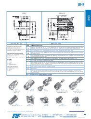
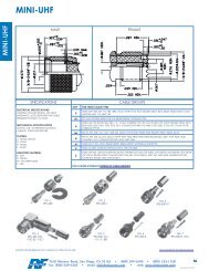
For many years, the UHF connector provided reliable service for applications through about 300 MHz.<br />
(FIG. 1) But with World War II, and emerging military needs for higher-frequency applications including<br />
communications and radar systems, the UHF connector—with its nonconstant impedance—was distinctly<br />
.CONNECTING THE WORLD.<br />
7610 Miramar Rd, San Diego, CA 92126 800-233-1728 858-549-6340 F:858-549-6345 E:rfi@rfindustries.com I:www.rfindustries.com
unsuitable for higher-frequency applications. A joint US<br />
Army-Navy <strong>RF</strong> Cable Coordinating Committee (AN<strong>RF</strong>CCC)<br />
was established in the early 1940s to develop electrical and<br />
mechanical standards for coaxial cables, connectors, and rigid<br />
high-frequency transmission lines for use with communications<br />
radios and radar systems. The committee’s goals and findings<br />
were later incorporated into the Armed Services Electro-<br />
Standards Agency (ASESA) and eventually wrapped into the<br />
Defense Electronics Supply Center (DESC), which continues<br />
present-day work on connector standardization for the US<br />
military.<br />
FIG. 1 – UHF Male and Female<br />
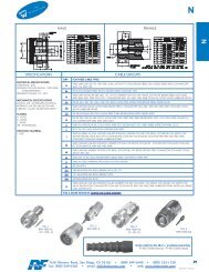
The AN<strong>RF</strong>CCC introduced the Type N connector with its threaded coupling nut and air interface in 1942.<br />
The new connector was named after Paul Neill of Bell Laboratories, also a member of the AN<strong>RF</strong>CCC. A<br />
high-voltage version of the Type N connector, the HN connector, was later released and then the Type C<br />
connector with a twist-lock coupling mechanism for rapid connection and disconnection. It was named<br />
after its inventor, Carl Concelman of Amphenol Corporation. Smaller coaxial connectors would follow<br />
including the bayonet-type BNC and threaded TNC connectors developed by Neill and Concelman.<br />
Type N connectors were originally covered in specifications written by the US Navy Bureau of Ships,<br />
which eventually became military specification MIL-C-71 until MIL-C-39012, was issued in 1964 to control<br />
the specifications for the Type N connector for military applications. Early Type N connectors had<br />
many shortcomings, prompting industrial suppliers to modify dimensions in their attempts to improve<br />
performance. A number of interface variations were developed, particularly by test and measurement<br />
companies for instrumentation applications, enabling Type N performance through about 18 GHz. But<br />
general-purpose Type N connectors, which perform to about 11 GHz, are covered under MIL-C-39012 for<br />
military applications.<br />
At present, one of the more popular coaxial <strong>RF</strong>/microwave connectors is the subminiature Type A or SMA<br />
connector. It began life as the Bendix real miniature (BRM) connector, designed by James Cheal of Bendix<br />
Research Laboratories in 1958 and eventually becoming the SMA connector as a result of work by Omni-<br />
Spectra (now M/A-COM Technology Solutions) to convert it into their Omni Spectra miniature (or OSM)<br />
connector. The SMA connector was originally intended for use with 0.141-in.-diameter semirigid coaxial<br />
cable, with the center conductor of the cable serving as the center pin for the connector. It would later be<br />
modified for use with flexible cables, using center pins directly soldered to the cable’s center conductor.<br />
In 1968, the SMA connector was incorporated into the MIL-C-39012 specifications where it was given its<br />
current designation as a subminiature A or SMA connector. Standard versions of SMA connectors can<br />
readily operate from DC to 18 GHz, with precision versions available for DC to 26.5 GHz.<br />
Connector pairs mate by means of different coupling techniques, including twist or bayonet locks, snapon<br />
fixtures, and threaded connections. As the table shows, most connectors employ threaded coupling,<br />
including Type N and SMA connectors. Some connectors, such as SMB connectors, use a snap-on mating<br />
technique. One of the early, unique mating approaches is used in the BNC connector, which has a typical<br />
frequency range of DC to 4 GHz and can be fabricated for 50 or 75 Ω applications. Commonly found in<br />
low-power signal generators, oscilloscopes, and other test equipment, the BNC employs a bayonet-type<br />
retention collar that enables simple mating, but also provides a sound and repeatable electrical connection<br />
and helps prevent accidental disconnections, especially in high-vibration environments. The BNC features<br />
two bayonet lugs on the female connector, and quickly connects and disconnects with only a quarter<br />
turn of the coupling nut required for positive mating. Unfortunately, this coupling approach has its<br />
shortcomings at higher frequencies, when the standard BNC is subjected to EM radiation above 4 GHz. The<br />
— 2 —<br />
<strong>RF</strong> Industries (Nasdaq: <strong>RF</strong>IL)<br />
7610 Miramar Rd, San Diego, CA 92126 800-233-1728 858-549-6340 F:858-549-6345 E:rfi@rfindustries.com I:www.rfindustries.com
TNC connector is a threaded version of the BNC connector for use beyond 4 GHz, and shares all interface<br />
dimensions with the exception of their coupling nuts and mating surfaces.<br />
Numerous stories claim to tell the origins of the three-letter abbreviation for this connector, including the<br />
British Navy <strong>Connectors</strong> and the Bayonet Node <strong>Connectors</strong>. But, as yet another creation of connector gurus<br />
Neill and Concelman, the most likely full name is the Bayonet Neil-Concelman connector. BNC connectors<br />
are suitable for use with cables ranging in size from RG-174/U to RG-213/U, including RG59/U coaxial<br />
cables common in closed-circuit-television (CCTV) systems. The certainty and security of their coupling<br />
mechanism also makes them popular candidates for medical electronic equipment. Their specifications are<br />
covered by International Electrotechnical Commission (IEC) standard IEC60169-8 and MIL-C-39012.<br />
Antennas and replacements that must<br />
be tightly controlled according to<br />
Federal Communications Commission<br />
(FCC) requirements not to exceed a<br />
specified power level and/or operating<br />
bandwidth are subject to FCC Part<br />
15 unique connector requirements.<br />
By incorporating reverse-polarity<br />
interfaces, where gendered center<br />
conductors are reversed, or by the<br />
use of reverse threading on the<br />
connectors, it is possible to ensure<br />
that components using Part 15<br />
compliant interfaces or coupling will<br />
not mate with standard connectors<br />
and their components. The reversepolarity/reverse-threading<br />
approaches<br />
are used with various coaxial<br />
connector types, including Type N,<br />
BNC, TNC, MMCX, SMB, and SMA<br />
connectors.<br />
FIG. 2 – A 50 Ω impedance was chosen for high frequency connectors<br />
as the best compromise between the optimal impedance for handling<br />
power (30 Ω) and lowest attenuation (77 Ω).<br />
High-frequency connector impedances are typically 50 or 75 Ω. The impedance value for maximum<br />
power transfer is 30 Ω while the impedance for theoretical minimum attenuation is 77.5 Ω. High-frequency<br />
connectors represent something of a compromise between these two values, since their average is about<br />
50 Ω. (FIG. 2) When long transmission runs are needed, with minimal attenuation, such as in CATV systems,<br />
the concern is less with optimizing power transfer, so the higher-impedance 75 Ω connectors are typically<br />
used in those systems.<br />
Coaxial connectors are differentiated by gender: jack or female connectors and plug or male connectors.<br />
Standard connectors with male and female configurations join in a mated pair. The male contact is a pin and<br />
the female contact is a socket. Coaxial adapters make it possible to join connectors of the same sex, or to<br />
ease wear on a precision connector used on an expensive test instrument. Such adapters are often referred<br />
to as “connector savers” since they mate to the test connector and also provide a mating end for a cable<br />
assembly or coaxial component to be tested, putting the wear on the adapter rather than on the precision<br />
connector.<br />
Gendered connectors can be coplanar (FIG. 3) or noncoplanar (FIG. 4), and are usually gender matched in<br />
both inner and outer conductors, like Type N and SMA connectors. For a coplanar connector, the center<br />
and outer conductors mate in the same plane (such as SMA connectors). For noncoplanar connectors,<br />
— 3 —<br />
<strong>RF</strong> Industries (Nasdaq: <strong>RF</strong>IL)<br />
7610 Miramar Rd, San Diego, CA 92126 800-233-1728 858-549-6340 F:858-549-6345 E:rfi@rfindustries.com I:www.rfindustries.com
the center conductors do<br />
Coplanar<br />
not mate in the same plane<br />
as the outer conductors<br />
(such as Type N, BNC, and<br />
TNC connectors). Coaxial<br />
connectors can be designed<br />
with air or solid dielectrics,<br />
with polytetrafluoroethylene<br />
Male<br />
Female<br />
(PTFE or Teflon®), Delrin®,<br />
FIG. 3 – This cross sectional view represents a mated pair of SMA connectors.<br />
or thermoplastics serving as<br />
Noncoplanar<br />
common solid dielectric materials.<br />
Male<br />
Air serves as the optimum<br />
Female<br />
dielectric, followed by PTFE, then<br />
Delrin. <strong>Connectors</strong> with solid<br />
dielectrics can be flush or have<br />
overlapping configurations, with<br />
75 Ω BNC and 50 Ω SMA and<br />
SSMA connectors examples of<br />
flush connector configurations.<br />
Both 50 Ω TNC and BNC are<br />
examples of overlapping<br />
FIG. 4 – This cross sectional view represents a mated pair of Type N connectors.<br />
connector constructions, which<br />
are typically employed to prevent voltage breakdown and handle higher power levels.<br />
Comparing Building Materials<br />
Leading suppliers like <strong>RF</strong> Industries offer a wide range of coaxial connectors and adapters, among them<br />
SMA, Type N, 7/16 DIN, QMA, and 3.5 mm connectors. As has been noted, different connectors provide<br />
different features and benefits, including size, frequency range, and power-handling capabilities. But <strong>RF</strong><br />
Industries also provides some connectors, for example SMA or Type N, with a choice of different materials,<br />
such as brass or stainless-steel base material, with a variety of finishes, including gold, silver, nickel, white<br />
bronze, and passivation. But why so many choices?<br />
It may help to compare some of the different metals used in constructing coaxial connectors to understand<br />
their advantages and disadvantages in terms of connector performance. Materials for connectors can be<br />
evaluated in terms of their mechanical, electrical, and environmental properties, as well as how well the<br />
materials allow attachment to other materials, via soldering, crimping, or other process. Chosen materials<br />
should have good electrical conductivity, minimal resistance, good machinability, good stability over<br />
time, and good hardness to withstand repeated coupling cycles with minimal wear and performance<br />
deterioration. Many metals can suffer from surface corrosion, which can degrade electrical performance<br />
over time, so only appropriate metals are used. The choice of materials for a coaxial connector can greatly<br />
determine both reliability and electrical performance.<br />
Stainless steel, for example, is a steel alloy with a small amount of chromium content. It is formulated not<br />
to rust or corrode when exposed to moisture. It is a hard material that is extremely durable and often used<br />
for connector housings, although not for contact parts because of its hardness and relatively low electrical<br />
conductivity. It is higher in cost than bronze or brass, but features high stability, high durability, and<br />
outstanding corrosion resistance for high reliability in a variety of operating environments.<br />
— 4 —<br />
<strong>RF</strong> Industries (Nasdaq: <strong>RF</strong>IL)<br />
7610 Miramar Rd, San Diego, CA 92126 800-233-1728 858-549-6340 F:858-549-6345 E:rfi@rfindustries.com I:www.rfindustries.com
Less durable but lower in cost, brass is also used for connector housings as well as for connector contacts.<br />
It is essentially a copper-zinc alloy that is easily machined, being considerably softer than stainless steel. It<br />
is an excellent conductor of both heat and electricity, and provides good durability in most industrial and<br />
marine environments because it is not subject to corrosion from contaminants found in those environments.<br />
Connector parts are plated with different metals for various reasons, including: to improve the electrical and<br />
thermal conductivity, to improve the contact between conductors, and even to improve the solderability<br />
or weldability of a part. Noble metals, among them gold and silver, tend to be excellent conductors, and<br />
they are resistant to corrosion, but these are expensive materials, so thin layers are used on top of other<br />
metals when fabricating connectors. This makes it possible to take advantage of the electrical and thermal<br />
properties of the plated metal while using as little of the material as possible.<br />
Gold, for example, is an excellent conductor and it features very good oxidation resistance. It greatly<br />
enhances the electrical conductivity of connector parts made from copper or brass. But because of its high<br />
cost, gold is plated in thin layers, which can sometimes suffer from diffusion or a wearing away of the gold<br />
finish. To minimize gold diffusion, nickel (and sometimes copper) is used as an underplating beneath the<br />
gold layer.<br />
Silver is also a fine electrical and thermal conductor, but less expensive than gold. It also can be plated on<br />
materials like copper and brass to improve their electrical performance, can carry high current loads with<br />
very low loss, and is particularly good at minimizing PIM at high power levels. But, as with gold, silver has<br />
its drawbacks, and its main disadvantage is its tendency to tarnish when exposed to some contaminants,<br />
including sulphur-based materials and ozone. Fortunately, the effects of tarnishing can be minimized by<br />
passivation. Passivation, which can mean different things, usually refers to a process that restores the<br />
protective oxide layer to the surface of a metal, making it more resistant to rust and corrosion.<br />
These are some of the metals used in coaxial connector fabrication, and used by <strong>RF</strong> Industries in the<br />
construction of their high-performance SMA, Type N, 7/16 DIN, QMA, and 3.5 mm connectors. The firm’s<br />
SMA and Type N connectors are available with either stainless steel or brass housings, with numerous finish<br />
types. The SMA connectors can have passivated, nickel, or gold finishes, while the Type N connectors can<br />
be passivated or plated with nickel, silver, or white bronze. The white bronze finish offers an alternative to<br />
silver, without the tarnish problems, and without the PIM-inducing tendencies of nickel plating. The 7/16<br />
DIN connectors feature brass bodies with silver or white bronze finish, QMA connectors use brass with<br />
white bronze finish, and 3.5 mm connectors are constructed of 303 stainless steel with passivated finish to<br />
deter corrosion. In the cases where there are choices, it is often a clear tradeoff between lower cost (brass)<br />
and higher performance and operating lifetime (stainless steel). But the needs of a particular application<br />
may not be that obvious, and specifiers are invited to contact Technical Support for assistance in selecting<br />
coaxial connectors with the best combination of base materials and finishes.<br />
Sorting Through Specs<br />
Choosing a connector can be as simple as matching the type of connector already being used in a system,<br />
or as complex as evaluating a set of design requirements to find a connector that best meets those<br />
requirements. The starting point in specifying a coaxial connector for any <strong>RF</strong>/microwave design is frequency<br />
range, since any connector choice must provide adequate bandwidth for the application. As the table<br />
shows, coaxial connectors are available for many different frequency ranges, some broadband, and well<br />
into the millimeter-wave frequency range. Most applications will require connectors with a characteristic<br />
impedance of 50 Ω, but for those systems operating at 75 Ω, a number of connector types are available,<br />
including BNC and TNC connectors, which are typically used in applications below 3 GHz.<br />
— 5 —<br />
<strong>RF</strong> Industries (Nasdaq: <strong>RF</strong>IL)<br />
7610 Miramar Rd, San Diego, CA 92126 800-233-1728 858-549-6340 F:858-549-6345 E:rfi@rfindustries.com I:www.rfindustries.com
Electrically, coaxial connectors are evaluated by a number of different parameters, including maximum<br />
insertion loss (IL) and maximum voltage-standing-wave ratio (VSWR) as functions of frequency. The IL<br />
for a mated connector pair is simply 10log10(PR/PT), where PT is the power transmitted (or applied to a<br />
connector) and PR is the power received from the connector after losses. The maximum IL for a mated<br />
connector pair as a function of frequency, F (in GHz), can be found from the simple relationship:<br />
Maximum IL = X( F )0.5<br />
where X is a multiplication factor which varies from<br />
connector to connector pair.<br />
VSWR is the ratio of maximum and minimum<br />
voltages on a transmission line caused by the<br />
combination of a forward and reflected wave:<br />
VSWR = [1 + (Pr/Pf)0.5]/ [1 - (Pr/Pf)0.5]<br />
where<br />
Pr = the reflected power (in W) and<br />
Pf = the forward power (in W).<br />
FIG. 5 – This plot shows insertion loss versus<br />
frequency for a pair of SMA connectors as part of<br />
a 15-ft. cable assembly.<br />
Maximum VSWR can also be found as a function of<br />
frequency for a given mated connector pair from the relationship:<br />
Maximum VSWR = Y( F )0.5<br />
where Y is a factor that will yield some value of maximum VSWR,<br />
such as 1.02 + 0.1( F )0.5 which is 1.22:1 at 4 GHz and 1.32:1 at 9 GHz.<br />
Additional coaxial connector electrical parameters include maximum operating voltage (in VDC), insulation<br />
resistance (in MΩ), dielectric withstanding voltage, operating temperature range, and operating lifetime,<br />
in maximum number of matings. Some connectors, such as 7/16 DIN connectors, are designed for lowdistortion<br />
performance, in particular low passive intermodulation distortion (PIM). High PIM can impact<br />
the performance of communications systems that rely on digital modulation formats, and these specially<br />
characterized connectors can ensure minimal levels of connector PIM. The PIM characterization is usually<br />
applied to any coaxial cables as well, with the connectors considered as part of the system’s cable<br />
assemblies.<br />
All connectors have a finite operating lifetime, and any connector’s operating lifetime is specified by the<br />
number of mating cycles. No matter how well designed, a connector will eventually wear out and its<br />
performance will degrade with extended use. Connections and disconnections result in wear and tear on<br />
any connector.<br />
Some connector types are compatible with others, a trait that can serve well in some test-and-measurement<br />
applications. For example, SMA connectors tend to be compatible with 2.92 and 3.5 mm connectors,<br />
although they may not provide the full frequency range of those smaller connectors. Stainless steel<br />
connectors with air dielectrics are typically designed for 500 mating cycles, in comparison to a lesser<br />
number of mating cycles for most SMA connectors. Smaller, higher-frequency connectors, such as 2.4,<br />
1.85, and 1 mm connectors, do not cross-mate with SMA connectors, however. Especially for measurement<br />
applications, repeatability between different (although compatible) connector types can be achieved by<br />
using a torque wrench and maintaining a standard amount of torque, such as 8 to 12 in.-lbs. for most <strong>RF</strong>/<br />
— 6 —<br />
<strong>RF</strong> Industries (Nasdaq: <strong>RF</strong>IL)<br />
7610 Miramar Rd, San Diego, CA 92126 800-233-1728 858-549-6340 F:858-549-6345 E:rfi@rfindustries.com I:www.rfindustries.com
microwave connectors. It is important to note that insufficient coupling torque can result in degraded <strong>RF</strong>/<br />
microwave performance, while too much torque can damage a connector and shorten its operating lifetime.<br />
Connector suppliers like <strong>RF</strong> Industries characterize their connectors as mated pairs using microwave vectornetwork-analyzer<br />
(VNA) systems with wideband <strong>RF</strong>/microwave signal generators to measure forward and<br />
reverse power levels (i.e., transmission and reflection) through the mated connector pair. Additional test<br />
equipment, such as broadband power amplifiers, is also employed for evaluating maximum power levels<br />
through the connectors.<br />
Designers should be aware that some connector suppliers offer connectors in three different grades:<br />
commercial grade (for production and general-purpose use on standard components), general precision<br />
grade (as used on instrumentation and test equipment), and laboratory precision grade (for calibration<br />
and measurement standards) (FIG. 6). In many cases, the tighter tolerances required by some demanding<br />
applications can be met by one of these different grades of coaxial connector.<br />
Design engineers should let their list of electrical and mechanical requirements, including frequency<br />
range, insertion loss, VSWR, and performance in terms of operating temperature, shock, and vibration,<br />
help guide their choice of coaxial connectors. In addition to the starting electrical points of frequency,<br />
IL, and VSWR, specifiers consider not only how many mating cycles will be required, but the effects of<br />
shock, vibration, and operating temperature on the connector’s performance contributions to a system.<br />
Another consideration is which special connector configuration, such as crimp, clamp, PCB, or panel-mount<br />
connector, might be available for a particular application. Not to be forgotten, cost should also be factored<br />
in when considering the different benefits of a particular coaxial connector choice.<br />
As an example of a selection process for a design operating to 10 GHz, connectors under consideration<br />
would include Type N and SMA connectors, based on their operating frequency ranges. Both are 50 Ω<br />
connectors, with excellent electrical characteristics. The Type N connector exhibits maximum IL of about<br />
0.2 dB with maximum VSWR of 1.30:1 at 10 GHz. The SMA connector has the same IL performance, with<br />
lower maximum VSWR of about 1.25:1 at 10 GHz. Both are rated for 500 minimum mating operations and<br />
operating temperature ranges as wide as -65 to +165°C. The larger Type N connector achieves lower <strong>RF</strong><br />
FIG. 6 – Precision SMA connectors provide outstanding performance from DC through 26.5 GHz.<br />
— 7 —<br />
<strong>RF</strong> Industries (Nasdaq: <strong>RF</strong>IL)<br />
7610 Miramar Rd, San Diego, CA 92126 800-233-1728 858-549-6340 F:858-549-6345 E:rfi@rfindustries.com I:www.rfindustries.com
leakage at higher voltage and power than an SMA, at -80 dB compared to -60 dB for the SMA. The Type<br />
N connector is also rated for higher working voltage, at about 1500 V compared to about 500 V maximum<br />
for the SMA. In the case of this comparison, system requirements for high voltage and low <strong>RF</strong> leakage<br />
would put the choice in favor of the Type N connector. In addition, when a connector is being considered<br />
as part of a cable assembly, and a performance parameter such as power-handling performance (such as<br />
for a transmitter application) is a key consideration, it will be limited by the combination of the connector(s)<br />
and the cable. (For more on specifying coaxial cable assemblies, refer to the free white paper soon to be<br />
available from <strong>RF</strong> Industries.)<br />
In Summary<br />
Coaxial connectors range from DC through millimeter-wave frequencies and are available for <strong>RF</strong>/microwave<br />
applications through 125 GHz. Some high-frequency connectors increase in cost as they decrease in size.<br />
<strong>Connectors</strong> are available in grades from commercial to high precision. By carefully considering the needs of<br />
an application, however, the right connector can be found to best match that connector’s set of tradeoffs to<br />
that application.<br />
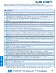
Comparing connectors: from audio to millimeter-wave frequencies<br />
Connector Type Frequency Range Coupling Impedance<br />
RCA DC to 10 MHz push on 75 Ω<br />
UHF DC to 300 MHz threaded 50 Ω<br />
BNC DC to 4 GHz twist-lock 50, 75 Ω<br />
TNC DC to 12.4 GHz threaded 50, 75 Ω<br />
TNC DC to 12.4 GHz reverse threaded 50 Ω<br />
Type N DC to 11 GHz threaded 50 Ω<br />
Type N DC to 11 GHz reverse threaded 50 Ω<br />
SMA DC to 18 GHz threaded 50 Ω<br />
SMA DC to 18 GHz reverse threaded 50 Ω<br />
SMB DC to 4 GHz snap on 50 Ω<br />
SMC DC to 10 GHz threaded 50 Ω<br />
SSMA DC to 40 GHz threaded 50 Ω<br />
C DC to 10 GHz twist-lock 50 Ω<br />
SC DC to 11 GHz twist-lock 50 Ω<br />
7 mm DC to 18 GHz threaded 50 Ω<br />
3.5 mm DC to 34 GHz threaded 50 Ω<br />
2.92 mm DC to 40 GHz threaded 50 Ω<br />
2.40 mm DC to 50 GHz threaded 50 Ω<br />
1.85 mm DC to 65 GHz threaded 50 Ω<br />
1.00 mm DC to 110 GHz threaded 50 Ω<br />
0.8 mm DC to 125 GHz threaded 50 Ω<br />
— 8 —<br />
<strong>RF</strong> Industries (Nasdaq: <strong>RF</strong>IL)<br />
7610 Miramar Rd, San Diego, CA 92126 800-233-1728 858-549-6340 F:858-549-6345 E:rfi@rfindustries.com I:www.rfindustries.com