Instruction Sheet - Vance & Hines
Instruction Sheet - Vance & Hines
Instruction Sheet - Vance & Hines

You also want an ePaper? Increase the reach of your titles
YUMPU automatically turns print PDFs into web optimized ePapers that Google loves.
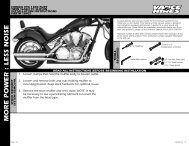
WHEN YOU KNOW THE DIFFERENCE<br />
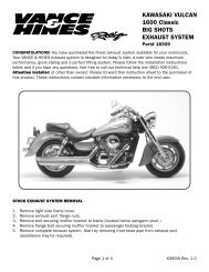
HARLEY-DAVIDSON ® DRESSER<br />
BIG SHOT DUALS<br />
INSTALLATION INSTRUCTIONS<br />
PART# 17917<br />
STOCK EXHAUST<br />
SYSTEM REMOVAL<br />
1. Remove both left and right saddlebags and set them aside.<br />
2. Loosen the bolt from the pinch clamp on the front end of each muffler.<br />
Note: On older model Dressers, spread the clamps just enough to remove<br />
them.<br />
3. Remove the two 5/16” bolts that mount the muffler to the saddlebag<br />
supports. Repeat this step on the opposite muffler.<br />
4. Remove the stock mufflers with sliding hangers and set them aside. Note: It<br />
may be necessary to use a penetrating lubricant to loosen the muffler from<br />
the head pipe.<br />
5. Remove the right hand floor board.<br />
6. Remove both passenger floor boards.<br />
7. Loosen the heat shield clamps on both front and rear exhaust pipes.<br />
8. Loosen the rear head pipe clamp located behind the rear cylinder. Remove<br />
the section of head pipe connecting the left side muffler.<br />
Congratulations, you have purchased the finest exhaust system<br />
for your motorcycle on the market. Your <strong>Vance</strong> & <strong>Hines</strong> exhaust<br />
system is designed and crafted for maximum performance, a<br />
perfect fit, a great sound and unbeatable style. Please follow the<br />
installation instructions below and if you have any questions,<br />
please call our technical support line at (562) 926-5291.<br />
Attention installer (if other than owner), please forward this<br />
instruction sheet to the owner of this product. These instructions<br />
contain valuable information to the end user.<br />
TOOLS<br />
REQUIRED<br />
READ ALL INSTRUCTIONS BEFORE BEGINNING INSTALLATION<br />
9. Remove the clamp holding the front head pipe to the transmission housing.<br />
10. Remove the two mounting nuts from each head pipe, located at the<br />
cylinder head. Carefully remove the head pipes and set them aside.<br />
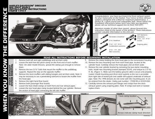
11. Remove the rear cylinder bracket by removing the two starter mounting<br />
bolts. Install new mounting bracket (stamped 353-P), and torque to (13-16)<br />
ft. lbs. (Figure 1). Make sure the battery ground cable is secure and properly<br />
routed. Install mounting post (from stock system) so the nut is accessible<br />
from right side of motorcycle and saddle will support underside of exhaust<br />
pipe. Note: Pre 1998 dressers do not come with this mounting post. It can<br />
be ordered from the dealer. Harley part number: 17048-98 or 65324-83A.<br />
12. Carefully remove the exhaust port flanges and circlips from the stock<br />
exhaust system using snapring pliers. Note: If circlips look bent or twisted<br />
replace them.<br />
FIGURE 1 FIGURE 2FIGURE 3 FIGURE 4<br />
T-bolt clamp location<br />
Install bracket<br />
353-P<br />
Install rear<br />
brackets<br />
377-P & 378-P<br />
Mark<br />
outside<br />
edge<br />
Flat blade screwdriver<br />
5/16” Nutdriver<br />
7/16”, 1/2”, 9/16”<br />
Combination wrenches<br />
3/16”, 1/4”, 3/8”<br />
Allen wrenches<br />
3/8” Ratchet &<br />
extensions<br />
7/16”, 1/2”, 9/16”<br />
sockets<br />
Snapring pliers<br />
Arrows indicate clamp head direction<br />
Page 1 of 4<br />
D485IN Rev. 1.0
FIGURE 5 FIGURE 6 FIGURE 7<br />
WHEN YOU KNOW THE DIFFERENCE<br />
FUELPAK VANCE & HINES EXHAUST<br />
SYSTEM INSTALLATION<br />
Install<br />
dogbone nutplate<br />
1. Install mounting brackets into rubber grommets in saddlebag mounting bar by<br />
sliding them in from the front (some light lubricant may be required)(Figure 2).<br />
Bracket marked 377-P is for the right side, and bracket 378-P is for the left.<br />
2. Remove head pipes and heat shields from protective packaging. Note: Removal<br />
of end cap may be required. Place each heat shield on a non-abrasive surface<br />
such as a blanket or carpet. Using a felt tip pen, mark outside edge of each heat<br />
shield to show location of mounting clips that hose clamps will loop through<br />
(Figure 3).<br />
3. Starting with the rear cylinder pipe, slide the T-bolt clamp onto the pipe so that<br />
it sits on the straight section of pipe closest to the cylinder head. When pipe is<br />
installed, clamp nut should hang under head pipe and point towards engine<br />
(Figure 4 & 6).<br />
4. Lay the head pipe into the heat shield and install each hose clamp by feeding tail<br />
end of clamps into heat shield clips. Take note of location of clamp screw head<br />
direction (Figure 3 & 4) (screw head must be accessible when system is installed<br />
on motorcycle for adjustment purposes).<br />
5. Install exhaust port flanges and circlips (from stock system) onto head pipes.<br />
6. Check the stock exhaust gaskets to be sure they are in good shape. If you have<br />
any doubts as to their condition, replace them. (Recommended replacement<br />
exhaust port gaskets, Harley part number:17048-98 or 65324-83A)<br />
7. Install complete assembly into rear exhaust port. Use stock flange nuts, do not<br />
tighten at this time.<br />
8. Attach exhaust pipe to bracket (378-P) using two 5/16“x 5/8” flange bolts and<br />
nutplate (supplied). Slide nutplate inside bracket which is welded to the backside<br />
of each muffler (Figure 5). Leave them loose at this time.<br />
9. Slide T-bolt clamp into position on pipe support bracket, do not tighten at this<br />
time (Figure 6).<br />
10. Install front head pipe, without heat shield, into front exhaust port. Use stock<br />
flange nuts. Attach exhaust pipe to bracket (377-P) using two 5/16“x 5/8” flange<br />
bolts and nutplate (supplied). Repeat procedure from left side.<br />
11. Install T-bolt clamp onto front head pipe looping through stock support bracket<br />
under transmission cover (Figure 7). Do not tighten at this time. It may be<br />
necessary to loosen two inside bolts of stock bracket to allow T-bolt clamp to slide<br />
through. Re-tighten once clamp is in place.<br />
12. Install each hose clamp into front heat shield by feeding tail end of clamps into<br />
heat shield clips. Take note of clamp screw head direction (Figure 4).<br />
13. Slide heat shield onto front head pipe from the rear and loosely tighten clamps.<br />
14. Install end caps (if removal was necessary) into tail end of each heat shield<br />
engaging head pipe and heat shield. Align mounting hole with end cap hole.<br />
Install and tighten 1/4”-20 button head screws. Note: Removable thread locking<br />
compound is recommended.<br />
15. Tighten cylinder port exhaust flange nuts on front and rear cylinders.<br />
16. Tighten the T-bolt clamps on the head pipes.<br />
17. Adjust the rear cylinder support bracket if necessary and tighten the securing nut.<br />
18. Tighten the hose clamps securing the heat shields<br />
19. Tighten the bolts securing the mufflers to the mounting brackets.<br />
20. Replace the right hand floor board using 1/2”x3/16” washers to space the<br />
floorboard away from the front head pipe.<br />
21. Replace both passenger floor boards. Note: Floorboards can be installed in three<br />
positions. Install both floorboards at the same height.<br />
22 Wipe any finger prints or oil off of the exhaust system.<br />
23. Be sure to tighten all hardware before starting your motorcycle.<br />
EXHAUST CARE - HELPFUL HINTS TO AVOID DISCOLORATION OF EXHAUST SYSTEM<br />
1. When installing a new set of chrome pipes, make sure your hands are clean and<br />
free of oil. After installation, thoroughly clean pipes with a soft cloth and cleaning<br />
solvent that will leave no residue (chrome wax / polish, glass cleaner, alcohol,<br />
ammonia, etc...) before starting the motorcycle.<br />
2. Follow owners manual instructions regarding use of the choke (starter enricher). If<br />
left on longer than recommended, discoloration may be accelerated.<br />
RE-JETTING FOR CARBURETED MODELS:<br />
Re-jetting the carburetors will result in realizing the “full” potential of this performance exhaust<br />
system. <strong>Vance</strong> & <strong>Hines</strong> offers Jet Kits for most applications, call (562) 921-7461 for more information.<br />
Page 2 of 4<br />
T-bolt clamp<br />
position<br />
3. Avoid long periods of idling as this can cause discoloraion.<br />
4. Intake leaks can cause the engine to run lean and overheat, this could lead to<br />
discoloration.<br />
5. Make sure there are no exhaust leaks at the junction of the exhaust pipes and<br />
cylinder head. We recommend replacing gaskets if they are worn.<br />
VANCE & HINES OPTIONAL ACCESSORIES<br />
FUEL MANAGEMENT FOR FUEL INJECTED MODELS:<br />
Take the guess work out of fuel injection with the new<br />
Fuelpak Fuel Management System, P/N 61003. Contact<br />
your local dealer or call (562) 921-7461 to order. Visit<br />
vanceandhines.com for more information.<br />
Install T-bolt<br />
clamp<br />
QUIET<br />
BAFFLE<br />
Quiet baffle P/N 21869 is available for this<br />
system. The quiet baffle will lower the sound<br />
level by 2-3db on average.Contact your local<br />
dealer to order.<br />
PLEASE NOTE:<br />
Every effort is made for <strong>Vance</strong> & <strong>Hines</strong> Exhaust Systems to provide improved cornering clearance.<br />
However, due to design and space limitations on some motorcycle models, ground and cornering<br />
clearance may not be improved and in some cases may be reduced. Be sure to follow proper<br />
installation instructions.<br />
D485IN Rev. 1.0
WHEN YOU KNOW THE DIFFERENCE<br />
HARLEY-DAVIDSON ® DRESSER<br />
BIG SHOT DUALS<br />
INSTALLATION INSTRUCTIONS<br />
PART# 17917<br />
ALL PARTS SHOWN ARE ACTUAL SIZE<br />
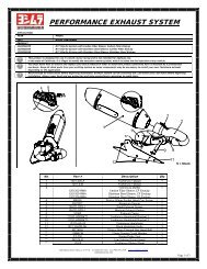
#28 Hose clamps<br />
x 2<br />
1/2” x 3/16”<br />
Washer x 4<br />
PACKING LIST<br />
#20 Hose clamps<br />
x 7<br />
#62 T-bolt clamp<br />
x 2<br />
WARRANTY<br />
5/16” x 5/8”<br />
Flange head bolt<br />
x 4<br />
Nutplate<br />
x 2<br />
PARTS NOT SHOWN:<br />
353-P Bracket x 1<br />
377-P Bracket x 1<br />
378-P Bracket x 1<br />
D380FC Front head pipe x 1<br />
D381FC Rear head pipe x 1<br />
D380HC Front heat shield x 1<br />
D381HC Rear heat shield x 1<br />
<strong>Vance</strong> & <strong>Hines</strong> exhaust systems are warranted against defects in material and workmanship for a period of 90 days from the date of purchase from an authorized dealer. This warranty does not cover<br />
discoloration of chrome finishes. This warranty is limited to the repair or replacement of a product proven to be defective from normal use. <strong>Vance</strong> & <strong>Hines</strong> exhaust systems are designed to fit and<br />
operate on OEM motor and chassis. This warranty does not cover any product subject to abuse, misuse, improper installation or modification.<br />
Page 3 of 4<br />
D485IN Rev. 1.0
GEAR<br />
WHEN YOU KNOW THE DIFFERENCE<br />
BILLET SLASH-CUT TIPS - 16921<br />
Page 4 of 4<br />
Big Radius<br />
SM 24024<br />
MD 24025<br />
LG 24026<br />
XL 24027<br />
XXL 24028<br />
Sideshots Vertical<br />
SM 24029<br />
MD 24030<br />
LG 24031<br />
XL 24032<br />
XXL 24033<br />
GET YOUR LIMITED EDITION VANCE & HINES T-SHIRT. ALL T-SHIRTS ARE BLACK, HIGH<br />
QUALITY, 100% COTTON AND MADE IN THE U.S.A. CALL TO ORDER: (562) 921-7461<br />
For even more style, customize your exhaust system<br />
with the Billet Slash-cut end tips.<br />
OPTIONAL TIPS<br />
V-Rod<br />
SM 24034<br />
MD 24035<br />
LG 24036<br />
XL 24037<br />
XXL 24038<br />
13861 ROSECRANS AVENUE / SANTA FE SPRINGS, CA 90670<br />
SALES: (562) 921-7461 / TECHNICAL: (562) 926-5291 / FAX: (562) 802-0110<br />
VANCEANDHINES.COM<br />
FISHTAIL II TIPS - 16923<br />
Sideshots Cubed<br />
SM 24039<br />
MD 24040<br />
LG 24041<br />
XL 24042<br />
XXL 24043<br />
Fishtail II end tips are 100% designed and manufactured by<br />
<strong>Vance</strong> & <strong>Hines</strong> and include the same level of quality and performance<br />
as our exhaust systems.<br />
D485IN Rev. 1.0