- Page 1 and 2:
KM-1500 SERVICE MANUAL Published in
- Page 3 and 4:
Safety precautions This booklet pro
- Page 5 and 6:
1. Installation Precautions WARNING
- Page 7 and 8:
• Do not pull on the AC power cor
- Page 9 and 10:
2DC (8) The eraser lamp does not tu
- Page 11 and 12:
2DC 1-1-1 Specifications Type......
- Page 13 and 14:
2DC (2) Operation panel * ⁄ ( ^ @
- Page 15 and 16:
2DC 1-3-1 Unpacking and installatio
- Page 17 and 18:
CAUTIONS • Be sure to hold both t
- Page 19 and 20:
2DC 3. Remove the nine tapes, the t
- Page 21 and 22:
2DC 3. Remove the process unit from
- Page 23 and 24:
2DC 9. Hold the process unit stable
- Page 25 and 26:
2DC Connect the power cord. 1. Conn
- Page 27 and 28:
2DC 4) Press down on the stopper ex
- Page 29 and 30:
2DC 1-3-2 Installing the document p
- Page 31 and 32:
2DC CAUTION Be sure to tighten the
- Page 33 and 34:
2DC 1-4-1 Maintenance mode The copi
- Page 35 and 36:
2DC Section Fixing and cleaning Ope
- Page 37 and 38:
2DC Maintenance item No. U005 U019
- Page 39 and 40:
2DC Maintenance item No. U030 U031
- Page 41 and 42:
2DC Maintenance item No. U063 U065
- Page 43 and 44:
2DC Maintenance item No. U087 Descr
- Page 45 and 46:
2DC Maintenance item No. U091 Descr
- Page 47 and 48:
2DC Maintenance item No. U093 Descr
- Page 49 and 50:
2DC Maintenance item No. U144 U157
- Page 51 and 52:
2DC Maintenance item No. U162 U163
- Page 53 and 54:
2DC Maintenance item No. U244 Descr
- Page 55 and 56:
2DC Maintenance item No. U258 U260
- Page 57 and 58:
2DC Maintenance item No. U402 U403
- Page 59 and 60:
2DC Maintenance item No. U905 U908
- Page 61 and 62:
2DC Maintenance item No. U911 U927
- Page 63 and 64:
2DC 1-5-1 Paper misfeed detection (
- Page 65 and 66:
Section Jam code Description Condit
- Page 67 and 68:
Problem Causes/check procedures Cor
- Page 69 and 70:
2DC • DP Problem Causes/check pro
- Page 71 and 72:
2DC Code Contents Causes Remarks Ch
- Page 73 and 74:
2DC Code Contents Causes Remarks Ch
- Page 75 and 76:
2DC 1-5-3 Image formation problems
- Page 77 and 78:
2DC (3) Image is too light. Causes
- Page 79 and 80:
2DC (9) Black dots appear on the im
- Page 81 and 82:
2DC (15)Fixing is poor. Causes 1. W
- Page 83 and 84:
Problem Causes Check procedures/cor
- Page 85 and 86:
2DC 1-5-5 Mechanical problems Probl
- Page 87 and 88:
2DC 1-6-2 Removing the process unit
- Page 89 and 90:
2DC (2) Removing the right cover 1.
- Page 91 and 92:
2DC 1-6-5 Removing the MP feed roll
- Page 93 and 94:
2DC 1-6-6 Removing the transfer rol
- Page 95 and 96:
2DC (2) Removing the main board 1.
- Page 97 and 98:
2DC (3) Removing the power supply b
- Page 99 and 100:
2DC 1-6-8 Removing the main motor a
- Page 101 and 102:
2DC 10. Remove the main board (See
- Page 103 and 104:
2DC 1-6-9 Removing and splitting th
- Page 105 and 106:
2DC (1) Removing the separation cla
- Page 107 and 108:
2DC (3) Removing the heat roller WA
- Page 109 and 110:
2DC (4) Removing the thermistor 1.
- Page 111 and 112: 2DC (6) Removing the press roller W
- Page 113 and 114: 2DC 4. Remove the two screws. 5. Sl
- Page 115 and 116: 2DC 6. Remove three screws. 7. Remo
- Page 117 and 118: 2DC 1-6-12 Removing the ISU unit 1.
- Page 119 and 120: 2DC 1-6-13 Removing the exposure la
- Page 121 and 122: 2DC 1-6-14 Removing the scanner mir
- Page 123 and 124: 2DC 7. Remove three screws and then
- Page 125 and 126: 2DC 1-6-16 Removing the main charge
- Page 127 and 128: 2DC (2) Adjusting the center line o
- Page 129 and 130: 2DC (4) Adjusting the amount of sla
- Page 131 and 132: 2DC (6) Adjusting magnification of
- Page 133 and 134: 2DC (8) Adjusting the scanner cente
- Page 135 and 136: 2DC (10) Adjusting the DP magnifica
- Page 137 and 138: 2DC (12) Adjusting the DP trailing
- Page 139 and 140: 2DC (14) Adjusting the margins for
- Page 141 and 142: 2DC 2-1-1 Paper feeding system The
- Page 143 and 144: 2DC (2) Paper feeding mechanism Dri
- Page 145 and 146: 2DC Scanner unit Original ISU unit
- Page 147 and 148: 2DC 2-1-3 Electrophotographic syste
- Page 149 and 150: 2DC (2) Main charging (2-1) Photo c
- Page 151 and 152: 2DC (3) Exposure The charged surfac
- Page 153 and 154: (3-2) Drum surface potential The la
- Page 155 and 156: (5) Transfer The image developed by
- Page 157 and 158: 2DC (6-1) Fuser unit mechanism 0 !
- Page 159 and 160: 2DC 2-2-1 Electrical parts layout (
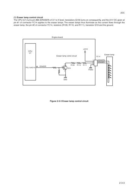
- Page 161: 2DC 2-3-1 Main board +5V ASIC debug
- Page 165 and 166: The AC power for the heater is appl
- Page 167 and 168: (3) Polygon motor control circuit T
- Page 169 and 170: 2DC 2-3-4 Bias board The bias board
- Page 171 and 172: (1) Interlock switch The interlock
- Page 173 and 174: 2DC 2-3-7 Operation board The opera
- Page 175 and 176: 2DC Timing chart No. 1 Continuous c
- Page 177 and 178: 2DC Timing chart No. 3 Continuous c
- Page 179: KYOCERA MITA EUROPE B.V. Hoeksteen