TDA1220B
TDA1220B
TDA1220B

You also want an ePaper? Increase the reach of your titles
YUMPU automatically turns print PDFs into web optimized ePapers that Google loves.
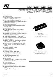
<strong>TDA1220B</strong><br />
AM-FM QUALITY RADIO<br />
The <strong>TDA1220B</strong> is a monolithic integrated circuit in<br />
a 16-lead dual in-line package.<br />
It is intended for quality receivers produced in large<br />
quantities.<br />
The functions incorporated are:<br />
AM SECTION<br />
– Preamplifier and double balanced mixer<br />
– One pin local oscillator<br />
– IF amplifier with internal AGC<br />
– Detector and audio preamplifier<br />
FM SECTION<br />
– IF amplifier and limiter<br />
– Quadrature detector<br />
– Audio preamplifier<br />
The <strong>TDA1220B</strong> is suitable up to 30MHz AM and for<br />
FM bands (including 450KHz narrow band) and<br />
features:<br />
– Very constant characteristics (3V to 16V)<br />
– High sensitivity and low noise<br />
– Very low tweet<br />
ORDERING NUMBER : TDA 1220BK<br />
DIP-16 Plastic<br />
(0.25)<br />
– Sensitivity regulation facility (*)<br />
– High recovered audio signal suited for stereo<br />
decoders and radio recorders<br />
– Very simple DC switching of AM-FM<br />
– Low current drain<br />
– AFC facility<br />
(*) Maximum AM sensitivity can be reduced by means of a resistor<br />
(5 to 12KΩ) between pin 4 and ground.<br />
BLOCK DIAGRAM<br />
March 1993<br />
1/18
<strong>TDA1220B</strong><br />
ABSOLUTE MAXIMUM RATINGS<br />
Symbol Parameter Value Unit<br />
V s Supply voltage 16 V<br />
Ptot Total power dissipation at T amb < 110°C 400 mW<br />
T op Operating temperature -20 to 85 °C<br />
T stg, T j Storage and junction temperature -55 to 150 °C<br />
PIN CONNECTION<br />
(Top view)<br />
THERMAL DATA<br />
Symbol Parameter Value Unit<br />
R th-j-amb Thermal resistance junction-ambient max 100 °C/W<br />
2/18
<strong>TDA1220B</strong><br />
ELECTRICAL CHARACTERISTICS ( T amb = 25 °C, V s = 9V unless otherwise specified, refer to test circuit)<br />
Symbol Parameter Test conditions Min. Typ. Max. Unit<br />
V s Supply voltage 3 16 V<br />
Id Drain current FM 10 15 mA<br />
AM 14 20 mA<br />
AM SECTION (f o = 1 MHz; f m = KHz)<br />
V i Input sensitivity S/N = 26 dB m = 0.3 12 25 µV<br />
S/N V i = 10 mV m = 0.3 45 52 dB<br />
V i AGC range ∆V out = 10 dB m = 0.8 94 100 dB<br />
V o<br />
Recovered audio signal<br />
(pin 9)<br />
V i = 1 mV m = 0.3 80 130 200 mV<br />
d<br />
Distortion<br />
V i = 1 mV<br />
m = 0.3 0.4 1 %<br />
m = 0.8 1.2 %<br />
VH<br />
R i<br />
C i<br />
Max input signal handling<br />
capability<br />
Input resistance between<br />
pins 2 and 4<br />
Input capacitance between<br />
pins 2 and 4<br />
m = 0.8 d < 10% 1 V<br />
m = 0 7.5 KΩ<br />
m = 0 18 pF<br />
Ro Output resistance (pin 9) 4.5 7 9.5 KΩ<br />
Tweet 2 IF<br />
m = 0.3<br />
Vi = 1 mV<br />
40 dB<br />
Tweet 3 IF 55 dB<br />
FM SECTION (fo = 10.8 MHz; fm = 1 KHz)<br />
Vi Input limiting voltage -3 dB limiting point 22 36 µV<br />
AMR<br />
Amplitude modulation<br />
rejection<br />
∆f = ±22.5 KHz<br />
Vi = 3 mV<br />
m = 0.3 40 50 dB<br />
S/N Ultimate quieting ∆f = ±22.5 KHz Vi = 1 mV 55 65 dB<br />
d Distortion ∆f = ±75 KHz Vi = 1 mV 0.7 1.5 %<br />
d Distortion<br />
∆f = ±22.5 KHz V i = 1 mV<br />
0.25 0.5 %<br />
d Distortion (double tuned) 0.1 %<br />
V o<br />
Ri<br />
Ci<br />
Recovered audio signal<br />
(pin 9)<br />
Input resistance between<br />
pin 16 and ground<br />
Input capacitance between<br />
pin 16 and ground<br />
∆f = ±22.5 KHz Vi = 1 mV 80 110 140 mV<br />
6.5 KΩ<br />
14 pF<br />
R o Output resistance (pin 9) 4.5 7 9.5 KΩ<br />
3/18
<strong>TDA1220B</strong><br />
Figure 1. Test circuit<br />
Figure 2. PC board and component layout (1:1 scale) of the test circuit<br />
4/18
<strong>TDA1220B</strong><br />
Figure 3. Audio output, noise<br />
and tweet levels vs. input<br />
signal (AM section)<br />
Figure 4. Distortion vs. input<br />
signal and modulation index<br />
(AM section)<br />
Figure 5. Audio output vs.<br />
supply voltage (AM section)<br />
Figure 6. Audio output and<br />
noise level vs. input signal (FM<br />
section)<br />
Figure 7. Distortion vs. input<br />
signal (FM section)<br />
Figure 8. Audio output vs.<br />
supply voltage (FM section)<br />
Figure 9. Amplitude modulation<br />
rejection vs. input signal<br />
(FM section)<br />
Figure 10. ∆ DC output voltage<br />
(pin. 9) vs. frequency shift (FM<br />
section)<br />
Figure 11. ∆ DC output voltage<br />
(pin 9) vs. ambient<br />
temperature (FM section)<br />
5/18
<strong>TDA1220B</strong><br />
APPLICATION INFORMATION<br />
AM Section<br />
RF Amplifier and mixer stages<br />
The RF amplifier stage (pin 2) is connected directly to the secondary winding of the ferrite rod antenna or<br />
input tuned circuit. Bias is provided at pin 4 which must be adequately decoupled. The RF amplifier provides<br />
stable performance extending beyond 30 MHz.<br />
The Mixer employed is a double - balanced multiplier and the IF output at pin 3 is connected directly to the<br />
IF filter coil.<br />
Local oscillator<br />
The local oscillator is a cross coupled differential stage which oscillates at the frequency determined by the<br />
load on pin 1.<br />
The oscillator resonant circuit is transformer coupled to pin 1 to improve the Q factor and frequency stability.<br />
The oscillator level at pin 1 is about 100 mV rms and the performance extends beyond 30 MHz, however<br />
to enhance the stability and reduce to a minimum pulling effects of the AGC operation or supply voltage<br />
variations, a high C/L ratio should be used above 10 MHz.<br />
An external oscillator can be injected at pin 1. The level should be 50 mV rms and pin 1 should be connected<br />
to the supply via a 100W resistor.<br />
IF Amplifier Detector<br />
The IF amplifier is a wide band amplifier with a tuned output stage.<br />
The IF filters can be either LC or mixed LC/ceramic.<br />
AM detection occurs at pin 7. A detection capacitor is connected to pin 6 to reduce the radiation of spurious<br />
detector products.<br />
The Audio output is at pin 9 (for either AM or FM); the IF frequency is filtered by an external capacitor which<br />
is also used as the FM mono de-enphasis network. The audio output impedance is about 7KΩ and a high<br />
impedance load (~ 50KΩ) must be used.<br />
AGC<br />
Automatic gain control operates in two ways.<br />
With weak signals it acts on the IF gain, maintaining the maximum S/N. For strong signals a second circuit<br />
intervenes which controls the entire chain and allows signal handling in excess of one volt (m = 0.8).<br />
At pin 8 there is a carrier envelope signal which is filtered by an external capacitor to remove the Audio and<br />
RF content and obtain a mean DC signal to drive the AGC circuit.<br />
6/18
<strong>TDA1220B</strong><br />
APPLICATION INFORMATION (continued)<br />
FM Section<br />
IF Amplifier and limiter<br />
The 10.7 MHz IF signal from the ceramic filter is amplified and limited by a chain of four differential stages.<br />
Pin 16 is the amplifier input and has a typical input impedance of 6.5 KW in parallel with 14 pF at 10.7 MHz.<br />
Bias for the first stage is available at pin 14 and provides 100% DC feedback for stable operating conditions.<br />
Pin 15 is the second input to the amplifier and is decoupled to pin 14, which is grounded by a 20 nF capacitor.<br />
An RLC network is connected to the amplifier output and gives a 90° phase shift (at the IF centre frequency)<br />
between pins 13 and 12. The signal level at pin 13 is about 150 mV rms<br />
FM Detector<br />
The circuit uses a quadrature detector and the choise of component values is determined by the acceptable<br />
level of distortion at a given recovered audio level.<br />
With a double tuned network the linearity improves (distortion is reduced) and the phase shift can be<br />
optimized; however this leads to a reduction in the level of the recovered audio. A satisfactory compromise<br />
for most FM receiver applications is shown in the test circuit.<br />
Care shoul be taken with the physical layout.<br />
The main recommandations are:<br />
• Locate the phase shift coil as near as possible to pin 13.<br />
• Shunt pins 14 and 16 with a low value resistor (between 56Ω and 330Ω).<br />
• Ground the decoupling capacitor of pin 14 and the 10.7 MHz input filter at the same point.<br />
AM-FM Switching<br />
AM-FM switching is achieved by applying a DC voltage at pin 13, to switch the internal reference.<br />
Typical DC voltages (refer to the test circuit)<br />
Pins 1 2 3 4 5 6 7 8 9 10 11 12 13 14 15 16 Unit<br />
AM 9 1.4 9 1.4 1.4 8.4 9 0.7 1.9 9 0 0.1 0.1 8.5 8.5 8.5 V<br />
FM 9 0.02 9 0.02 0.02 8.5 9 0 1.7 9 0 9 9 8 8 8 V<br />
7/18
<strong>TDA1220B</strong><br />
APPLICATION SUGGESTION<br />
Reccomended values are referred to the test circuit of Fig. 2.<br />
Part<br />
number<br />
Recommended<br />
value<br />
Purpose<br />
Smaller than<br />
recommended value<br />
Larger than<br />
recommended value<br />
C1 100 µF AGC bypass Increase of the distortion<br />
at low audio frequency<br />
Increase of the AGC time<br />
constant<br />
C2 (*) 100 nF AM input<br />
DC cut<br />
C3 (*) 10 nF FM input<br />
DC cut<br />
C4<br />
C5<br />
20 nF<br />
20 nF<br />
FM amplifier bypass Reduction of sensitivity – Bandwidth increase<br />
– Higher noise<br />
C6 68 pF Ceramic filter coupling IF bandwidth reduction IF bandwidth increase<br />
C7 100 nF FM detector decoupling Danger of RF irradiation<br />
C8 100 nF Power supply bypass Noise increase of the<br />
audio output<br />
C9 10 µF AGC bypass Increase of the distortion<br />
at low audio frequency<br />
Increase of the AGC time<br />
constant<br />
C10 (*) 56 pF Tuning of the AM<br />
oscillator at 1455 KHz<br />
C11 6.8 nF 50 µs<br />
FM de-enphasis<br />
C12 100 nF Output DC<br />
decoupling<br />
C13 220 µF Power supply<br />
decoupling<br />
Low audio frequency cut<br />
Increase of the distortion<br />
at low frequency<br />
C16 2.7 nF AM detector capacitor Low suppression of<br />
the IF frequency and<br />
harmonics<br />
Increase of the audio<br />
distortion<br />
R1 (*) 68 ohm FM input matching<br />
R2 (*) 56 ohm AM input matching<br />
R3 330 ohm Ceramic filter matching Audio output decrease<br />
and lower distortion<br />
R4 8.2 Kohm FM detector<br />
coil Q setting<br />
R5 560 ohm FM detector<br />
load resistor<br />
R6 82 Kohm AM detector<br />
coil Q setting<br />
R7 2.2 Kohm 455 KHz IF filter<br />
matching<br />
R8 3.3 Kohm 455 KHz IF filter<br />
matching<br />
(*) Only for test circuit<br />
Audio output decrease<br />
and higher AMR<br />
Lower IF gain and Lower<br />
AGC range<br />
Audio output increase<br />
and higher distortion<br />
Higher IF gain and lower<br />
AGC range<br />
8/18
<strong>TDA1220B</strong><br />
APPLICATION INFORMATION (continued)<br />
Figure 12. Portable AM/FM radio<br />
9/18
<strong>TDA1220B</strong><br />
APPLICATION INFORMATION (continued)<br />
Figure 13. PC board and component layout of the fig. 12 1 : 1 scale<br />
10/18
<strong>TDA1220B</strong><br />
APPLICATION INFORMATION (continued)<br />
F1 - 10.7 MHz IF Coil<br />
C o<br />
(pF) f<br />
(MHz)<br />
Q o<br />
TURNS<br />
– 1-3 1-2 2-3 4-6<br />
– 10.7 110 6 8 2<br />
TOKO - FM1 - 10x10 mm.<br />
154 AN - 7A5965R<br />
F3 and F5 - 455 KHz IF Coil<br />
Co<br />
(pF) f<br />
(KHz)<br />
Qo<br />
TURNS<br />
1.3 1-3 1-2 2-3 4-6<br />
180 455 70 57 116 24<br />
TOKO - AM3 - 10x10 mm.<br />
RLC - 4A7525N<br />
F4 - FM Detector Coil<br />
Co<br />
(pF) f<br />
(KHz)<br />
Qo<br />
TURNS<br />
1.3 1-3 1-3 – –<br />
82 10.7 100 12 – –<br />
TOKO - 10x10 mm.<br />
KACS - K586 HM<br />
F6 - AM Oscillator Coil<br />
f<br />
(kHz)<br />
L<br />
(µH)<br />
1-3<br />
Q o<br />
TURNS<br />
1-3 1-2 2-3 4-6<br />
796 220 80 2 75 8<br />
TOKO - 10x10 mm.<br />
RWO + 6A6574N<br />
L5 - Antenna Coil<br />
f<br />
(KHz)<br />
L<br />
Qo TURNS<br />
(µH)<br />
1-2 1-2 1-2 3-4<br />
796 105 7<br />
WIRE: LITZ - 15x0.05 mm.<br />
CORE: 10x80 mm.<br />
11/18
<strong>TDA1220B</strong><br />
APPLICATION INFORMATION (continued)<br />
Typical performance of the radio receiver of fig. 12 (Vs = 9V)<br />
Parameter Test Conditions Value<br />
WAVEBANDS<br />
FM<br />
AM<br />
87.5 to 108 MHz<br />
510 to 1620 KHz<br />
SENSITIVITY<br />
FM S/N = 26dB ∆f = 22.5KHz 1 µV<br />
AM S/N = 6dB m = 0.3 1 µV<br />
AM S/N = 26dB m = 0.3 10 µV<br />
DISTORTION<br />
(fm = 1KHz)<br />
FM P o = 0.5W<br />
AM Vi = 100 µV<br />
∆f = 22.5KHz 0.25%<br />
∆f = 75KHz 0,7%<br />
m = 0.3 0.4%<br />
m = 0,8 0,8%<br />
SIGNAL TO NOISE<br />
(fm = 1KHz)<br />
FM<br />
AM<br />
P o = 0.5W<br />
V i = 100 µV<br />
P o = 0.5W<br />
V i = 1 mV<br />
∆f = 22.5KHz<br />
m = 0.3<br />
64 dB<br />
50 dB<br />
AMPLITUDE<br />
MODULATION<br />
REJECTION<br />
TWEET<br />
QUIESCENT CURRENT<br />
FM Vi = 100 µV ∆f = 22.5KHz m = 0.3 50 dB<br />
2nd H. f = 911 KHz 0.3%<br />
3rd H. f = 1370 KHz 0.07%<br />
20 mA<br />
SUPPLY VOLTAGE RANGE<br />
3 to 12V<br />
12/18
<strong>TDA1220B</strong><br />
APPLICATION INFORMATION (continued)<br />
Figure 14. Low cost 27 MHz receiver<br />
Figure 15. L2 Oscillator coil<br />
Figure 16. L1 Antenna Coil<br />
Coil support: Toko 10K<br />
Primary winding: 10 Turns of enamelled copper<br />
wire 0.16 mm diameter (pins 3-1).<br />
Secondary winding: 4 Turns copper wire<br />
0.16 mm diameter (pins 6-4)<br />
Coil support: Toko 10K<br />
Primary winding: as L2 (pins 3-1)<br />
Secondary winding: 2 Turns copper wire<br />
0.16 mm diameter (pins 6-4)<br />
Figure 17. Low cost 27 MHz receiver with external xtal oscillator<br />
13/18
<strong>TDA1220B</strong><br />
APPLICATION INFORMATION (continued)<br />
Figure 18. 455 KHz FM narrow band IF<br />
Figure 18. P.C. board and component layout of the circuit of fig. 18<br />
14/18
<strong>TDA1220B</strong><br />
APPLICATION INFORMATION (continued)<br />
Figure 20. Discriminator "S" curve response (circuit of fig. 18)<br />
Figure 21. Application in sound channel of multistandard TV or in parallel AM modulated sound<br />
channel (AM section only).<br />
15/18
<strong>TDA1220B</strong><br />
ELECTRICAL CHARACTERISTICS (Vs = 12V)<br />
AM Section (f o = 39MHz; f m = 15KHz)<br />
Parameter Typ Unit<br />
Audio out (m = 0.3) 60 mV<br />
S/N (V i = 100 mV; m = 0.3) 37 dB<br />
S/N (V i = 1mV; m = 0.3) 55 dB<br />
S/N (V i = 10mV; m = 0.3) 56 dB<br />
AGC range (m = 0.8, ∆V out = 3dB) 65 dB<br />
Max input signal handling (m = 0.8; d = 5%) 150 mV<br />
– 3dB bandwidth 600 KHz<br />
Distortion (Vi = 100 µV; m = 0.3) 2 %<br />
(Vi = 1mV; m = 0.3) 1 %<br />
(Vi = 10mV; m = 0.3) 0.8 %<br />
(Vi = 100 µV; m = 0.8) 7 %<br />
(V i = 1mV; m = 0.8) 5 %<br />
(V i = 10mV; m = 0.8) 3 %<br />
FM Section (f o = 5.5MHz; f m = 1KHz)<br />
Parameter Typ Unit<br />
–3dB input limiting voltage (∆f = 25KHz) 3 µV<br />
AMR (∆f = +25KHz; m = 0.3; V i = 100 µV) 40 dB<br />
(∆f = +25KHz; m = 0.3; V i = 1mV) 58 dB<br />
(∆f = +25KHz; m = 0.3; V i = 10mV) 54 dB<br />
S/N (∆f = ±25KHz; V i = 100 µV) 51 dB<br />
S/N (∆f = ±25KHz; V i = 1 mV) 70 dB<br />
S/N (∆f = ±25KHz; V i = 10mV) 70 dB<br />
Distortion (∆f = ±25KHz; V i = 100 µV) 0.5 %<br />
(∆f = ±25KHz; V i = 1 mV) 0.6 %<br />
(∆f = ±25KHz; Vi = 10 mV) 0.6 %<br />
(∆f = ±50KHz; Vi = 100 µV) 1 %<br />
(∆f = ±50KHz V i = 1mV) 1 %<br />
(∆f = ±50KHz; V i = 10mV) 1 %<br />
Recovered audio (∆f = ±15KHz; V i = 1 mV)<br />
Recovered audio can be varied by variation of 3.3K ohm resistor in parallel with<br />
the discriminator coil)<br />
70 mV<br />
Max input signal handling 1 V<br />
Note: AM performance at 39MHz can be improved by mean of a selective preamplifier stage.<br />
16/18
<strong>TDA1220B</strong><br />
DIP16 PACKAGE MECHANICAL DATA<br />
DIM.<br />
mm<br />
inch<br />
MIN. TYP. MAX. MIN. TYP. MAX.<br />
a1 0.51 0.020<br />
B 0.77 1.65 0.030 0.065<br />
b 0.5 0.020<br />
b1 0.25 0.010<br />
D 20 0.787<br />
E 8.5 0.335<br />
e 2.54 0.100<br />
e3 17.78 0.700<br />
F 7.1 0.280<br />
I 5.1 0.201<br />
L 3.3 0.130<br />
Z 1.27 0.050<br />
17/18
<strong>TDA1220B</strong><br />
Information furnished is believed to be accurate and reliable. However, SGS-THOMSON Microelectronics assumes no responsibility for the<br />
consequences of use of such information nor for any infringement of patents or other rights of third parties which may result from its use. No<br />
license is granted by implication or otherwise under any patent or patent rights of SGS-THOMSON Microelectronics. Specifications mentioned<br />
in this publication are subject to change without notice. This publication supersedes and replaces all information previously supplied.<br />
SGS-THOMSON Microelectronics products are not authorized for use as critical components in life support devices or systems without express<br />
written approval of SGS-THOMSON Microelectronics.<br />
© 1994 SGS-THOMSON Microelectronics - All Rights Reserved<br />
SGS-THOMSON Microelectronics GROUP OF COMPANIES<br />
Australia - Brazil - France - Germany - Hong Kong - Italy - Japan - Korea - Malaysia - Malta - Morocco - The Netherlands - Singapore -<br />
Spain - Sweden - Switzerland - Taiwan - Thaliand - United Kingdom - U.S.A.<br />
18/18