MC44603 Mixed Frequency Mode GreenLine™ PWM Controller:
MC44603 Mixed Frequency Mode GreenLine™ PWM Controller:
MC44603 Mixed Frequency Mode GreenLine™ PWM Controller:

Create successful ePaper yourself
Turn your PDF publications into a flip-book with our unique Google optimized e-Paper software.
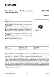
Order this document by <strong>MC44603</strong>/D<br />
<br />
<br />
<br />
<br />
Fixed <strong>Frequency</strong>, Variable <strong>Frequency</strong>,<br />
Standby <strong>Mode</strong><br />
The <strong>MC44603</strong> is an enhanced high performance controller that is<br />
specifically designed for off–line and dc–to–dc converter applications. This<br />
device has the unique ability of automatically changing operating modes if<br />
the converter output is overloaded, unloaded, or shorted, offering the<br />
designer additional protection for increased system reliability. The <strong>MC44603</strong><br />
has several distinguishing features when compared to conventional SMPS<br />
controllers. These features consist of a foldback facility for overload<br />
protection, a standby mode when the converter output is slightly loaded, a<br />
demagnetization detection for reduced switching stresses on transistor and<br />
diodes, and a high current totem pole output ideally suited for driving a power<br />
MOSFET. It can also be used for driving a bipolar transistor in low power<br />
converters (< 150 W). It is optimized to operate in discontinuous mode but<br />
can also operate in continuous mode. Its advanced design allows use in<br />
current mode or voltage mode control applications.<br />
Current or Voltage <strong>Mode</strong> <strong>Controller</strong><br />
• Operation up to 250 kHz Output Switching <strong>Frequency</strong><br />
• Inherent Feed Forward Compensation<br />
• Latching <strong>PWM</strong> for Cycle–by–Cycle Current Limiting<br />
• Oscillator with Precise <strong>Frequency</strong> Control<br />
High Flexibility<br />
• Externally Programmable Reference Current<br />
• Secondary or Primary Sensing<br />
• Synchronization Facility<br />
• High Current Totem Pole Output<br />
• Undervoltage Lockout with Hysteresis<br />
Safety/Protection Features<br />
• Overvoltage Protection Against Open Current and Open Voltage Loop<br />
• Protection Against Short Circuit on Oscillator Pin<br />
• Fully Programmable Foldback<br />
• Soft–Start Feature<br />
• Accurate Maximum Duty Cycle Setting<br />
• Demagnetization (Zero Current Detection) Protection<br />
• Internally Trimmed Reference<br />
GreenLine <strong>Controller</strong>: Low Power Consumption in Standby <strong>Mode</strong><br />
• Low Startup and Operating Current<br />
• Fully Programmable Standby <strong>Mode</strong><br />
• Controlled <strong>Frequency</strong> Reduction in Standby <strong>Mode</strong><br />
• Low dV/dT for Low EMI Radiations<br />
GreenLine is a trademark of Motorola, Inc.<br />
This document contains information on a new product. Specifications and information herein<br />
are subject to change without notice.<br />
MOTOROLA ANALOG IC DEVICE DATA<br />
MIXED FREQUENCY MODE<br />
GREENLINE <strong>PWM</strong>*<br />
CONTROLLER:<br />
Device<br />
<strong>MC44603</strong>P<br />
V CC<br />
V C<br />
Output<br />
Gnd<br />
Foldback Input<br />
Overvoltage<br />
Protection (OVP)<br />
Current Sense Input<br />
Demag Detection<br />
<strong>MC44603</strong>DW<br />
VARIABLE FREQUENCY,<br />
FIXED FREQUENCY,<br />
STANDBY MODE<br />
* <strong>PWM</strong> = Pulse Width Modulation<br />
16<br />
P SUFFIX<br />
PLASTIC PACKAGE<br />
CASE 648<br />
16<br />
1<br />
2<br />
3<br />
4<br />
5<br />
6<br />
7<br />
8<br />
1<br />
1<br />
DW SUFFIX<br />
PLASTIC PACKAGE<br />
CASE 751G<br />
(SOP–16L)<br />
PIN CONNECTIONS<br />
(Top View)<br />
ORDERING INFORMATION<br />
Operating<br />
Temperature Range<br />
TA = –25° to +85°C<br />
16 R ref<br />
R<br />
15 <strong>Frequency</strong><br />
Standby<br />
Voltage Feedback<br />
14<br />
Input<br />
13 Error Amp Output<br />
12 R Power Standby<br />
11<br />
Soft–Start/D max /<br />
Voltage <strong>Mode</strong><br />
10 C T<br />
9<br />
Sync Input<br />
Package<br />
Plastic DIP–16<br />
SOP–16L<br />
© Motorola, Inc. 1996 Rev 0<br />
1
MAXIMUM RATINGS<br />
<strong>MC44603</strong><br />
Rating Symbol Value Unit<br />
Total Power Supply and Zener Current (ICC + IZ) 30 mA<br />
Supply Voltage with Respect to Ground (Pin 4)<br />
VC<br />
VCC<br />
Output Current (Note 1)<br />
Source IO(Source) –750<br />
Sink IO(Sink) 750<br />
18 V<br />
Output Energy (Capacitive Load per Cycle) W 5.0 µJ<br />
RF Stby, CT, Soft–Start, Rref, RP Stby Inputs Vin –0.3 to 5.5 V<br />
Foldback Input, Current Sense Input,<br />
E/A Output, Voltage Feedback Input,<br />
Overvoltage Protection, Synchronization Input<br />
Vin<br />
–0.3 to<br />
VCC + 0.3<br />
Synchronization Input<br />
High State Voltage VIH VCC + 0.3 V<br />
Low State Reverse Current VIL –20 mA<br />
Demagnetization Detection Input Current<br />
Source Idemag–ib (Source) –4.0<br />
Sink Idemag–ib (Sink) 10<br />
Error Amplifier Output Sink Current IE/A (Sink) 20 mA<br />
Power Dissipation and Thermal Characteristics<br />
P Suffix, Dual–In–Line, Case 648<br />
Maximum Power Dissipation at TA = 85°C PD 0.6 W<br />
Thermal Resistance, Junction–to–Air RθJA 100 °C/W<br />
DW Suffix, Surface Mount, Case 751G<br />
Maximum Power Dissipation at TA = 85°C PD 0.45 W<br />
Thermal Resistance, Junction–to–Air RθJA 145 °C/W<br />
Operating Junction Temperature TJ 150 °C<br />
Operating Ambient Temperature TA –25 to +85 °C<br />
NOTES: 1. Maximum package power dissipation limits must be observed.<br />
2. ESD data available upon request.<br />
mA<br />
V<br />
mA<br />
ELECTRICAL CHARACTERISTICS (VCC and VC = 12 V, [Note 3], Rref = 10 kΩ, CT = 820 pF, for typical values TA = 25°C,<br />
for min/max values TA = –25° to +85°C [Note 4], unless otherwise noted.)<br />
Characteristic Symbol Min Typ Max Unit<br />
OUTPUT SECTION<br />
Output Voltage (Note 5)<br />
V<br />
Low State (ISink = 100 mA)<br />
Low State (ISink = 500 mA)<br />
High State (ISource = 200 mA)<br />
High State (ISource = 500 mA)<br />
VOL –<br />
–<br />
VOH –<br />
–<br />
Output Voltage During Initialization Phase VOL V<br />
VCC = 0 to 1.0 V, ISink = 10 µA<br />
– – 1.0<br />
VCC = 10to50V 1.0 5.0 V, ISink = 100 µA<br />
– 01 0.1 10 1.0<br />
VCC =50to13V 5.0 V, ISink =10mA<br />
1.0 – 01 0.1 10 1.0<br />
Output Voltage Rising Edge Slew–Rate (CL = 1.0 nF, TJ = 25°C) dVo/dT – 300 – V/µs<br />
Output Voltage Falling Edge Slew–Rate (CL = 1.0 nF, TJ = 25°C) dVo/dT – –300 – V/µs<br />
ERROR AMPLIFIER SECTION<br />
Voltage Feedback Input (VE/A out = 2.5 V) VFB 2.42 2.5 2.58 V<br />
Input Bias Current (VFB = 2.5 V) IFB–ib –2.0 –0.6 – µA<br />
Open Loop Voltage Gain (VE/A out = 2.0 to 4.0 V) AVOL 65 70 – dB<br />
NOTES: 3. Adjust V CC above the startup threshold before setting to 12 V.<br />
4. Low duty cycle pulse techniques are used during test to maintain junction temperature as close to ambient as possible.<br />
5. V C must be greater than 5.0 V.<br />
1.0<br />
1.4<br />
1.5<br />
2.0<br />
1.2<br />
2.0<br />
2.0<br />
2.7<br />
2 MOTOROLA ANALOG IC DEVICE DATA
<strong>MC44603</strong><br />
ELECTRICAL CHARACTERISTICS (continued) (VCC and VC = 12 V, [Note 3], Rref = 10 kΩ, CT = 820 pF, for typical values TA = 25°C,<br />
for min/max values TA = –25° to +85°C [Note 4], unless otherwise noted.)<br />
Characteristic Symbol Min Typ Max Unit<br />
ERROR AMPLIFIER SECTION (continued)<br />
Unity Gain Bandwidth BW MHz<br />
TJ = 25°C – 4.0 –<br />
TJ = –25° to +85°C – – 5.5<br />
Voltage Feedback Input Line Regulation (VCC = 10 to 15 V) VFBline–reg –10 – 10 mV<br />
Output Current<br />
Sink (VE/A out = 1.5 V, VFB = 2.7 V)<br />
TA = –25° to +85°C<br />
Source (VE/A out = 5.0 V, VFB = 2.3 V)<br />
TA = –25° to +85°C<br />
ISink 2.0 12 –<br />
ISource –2.0 – –0.2<br />
Output Voltage Swing<br />
High State (IE/A out (source) = 0.5 mA, VFB = 2.3 V) VOH 5.5 6.5 7.5<br />
Low State (IE/A out (sink) = 0.33 mA, VFB = 2.7 V) VOL – 1.0 1.1<br />
REFERENCE SECTION<br />
Reference Output Voltage (VCC = 10 to 15 V) Vref 2.4 2.5 2.6 V<br />
Reference Current Range (Iref = Vref/Rref, R = 5.0 k to 25 kΩ) Iref –500 – –100 µA<br />
Reference Voltage Over Iref Range ∆Vref –40 – 40 mV<br />
OSCILLATOR AND SYNCHRONIZATION SECTION<br />
<strong>Frequency</strong> fOSC kHz<br />
TA = 0° to +70°C 44.5 48 51.5<br />
TA = –25° to +85°C 44 – 52<br />
<strong>Frequency</strong> Change with Voltage (VCC = 10 to 15 V) ∆fOSC/∆V – 0.05 – %/V<br />
<strong>Frequency</strong> Change with Temperature (TA = –25° to +85°C) ∆fOSC/∆T – 0.05 – %/°C<br />
Oscillator Voltage Swing (Peak–to–Peak) VOSC(pp) 1.65 1.8 1.95 V<br />
Ratio Charge Current/Reference Current Icharge/Iref –<br />
TA = 0° to +70°C (VCT = 2.0 V) 0.375 0.4 0.425<br />
TA = –25° to +85°C 0.37 – 0.43<br />
Fixed Maximum Duty Cycle = Idischarge/(Idischarge + Icharge) D 78 80 82 %<br />
Ratio Standby Discharge Current versus IR F Stby (Note 6) Idisch–Stby/ –<br />
TA = 0° to +70°C IR F Stby 0.46 0.53 0.6<br />
TA = –25° to +85°C (Note 8) 0.43 – 0.63<br />
VR F Stby (IR F Stby = 100 µA) VR F Stby 2.4 2.5 2.6 V<br />
<strong>Frequency</strong> in Standby <strong>Mode</strong> (RF Stby (Pin 15) = 25 kΩ) FStby 18 21 24 kHz<br />
Current Range IR F Stby –200 – –50 µA<br />
Synchronization Input Threshold Voltage (Note 7)<br />
VinthH<br />
VinthL<br />
Synchronization Input Current ISync–in –5.0 – 0 µA<br />
Minimum Synchronization Pulse Width (Note 8) TSync – – 0.5 µs<br />
UNDERVOLTAGE LOCKOUT SECTION<br />
Startup Threshold Vstup–th 13.6 14.5 15.4 V<br />
Output Disable Voltage After Threshold Turn–On (UVLO 1) Vdisable1 V<br />
TA = 0° to +70°C 8.6 9.0 9.4<br />
TA = –25° to +85°C 8.3 – 9.6<br />
Reference Disable Voltage After Threshold Turn–On (UVLO 2) Vdisable2 7.0 7.5 8.0 V<br />
NOTES: 13. Adjust V CC above the startup threshold before setting to 12 V.<br />
14. Low duty cycle pulse techniques are used during test to maintain junction temperature as close to ambient as possible.<br />
16. Standby is disabled for V R P Stby < 25 mV typical.<br />
17. If not used, Synchronization input must be connected to Ground.<br />
18. Synchronization Pulse Width must be shorter than T OSC = 1/f OSC .<br />
3.2<br />
0.45<br />
3.7<br />
0.7<br />
4.3<br />
0.9<br />
mA<br />
V<br />
V<br />
MOTOROLA ANALOG IC DEVICE DATA<br />
3
<strong>MC44603</strong><br />
ELECTRICAL CHARACTERISTICS (continued) (VCC and VC = 12 V, [Note 3], Rref = 10 kΩ, CT = 820 pF, for typical values TA = 25°C,<br />
for min/max values TA = –25° to +85°C [Note 4], unless otherwise noted.)<br />
Characteristic Symbol Min Typ Max Unit<br />
DEMAGNETIZATION DETECTION SECTION (Note 9)<br />
Demagnetization Detect Input<br />
Demagnetization Comparator Threshold (VPin 9 Decreasing) Vdemag–th 50 65 80 mV<br />
Propagation Delay (Input to Output, Low to High) – – 0.25 – µs<br />
Input Bias Current (Vdemag = 65 mV) Idemag–lb –0.5 – – µA<br />
Negative Clamp Level (Idemag = –2.0 mA) CL(neg) – –0.38 – V<br />
Positive Clamp Level (Idemag = 2.0 mA) CL(pos) – 0.72 – V<br />
SOFT–START SECTION (Note 11)<br />
Ratio Charge Current/Iref Iss(ch)/Iref –<br />
TA = 0° to +70°C 0.37 0.4 0.43<br />
TA = –25° to +85°C 0.36 – 0.44<br />
Discharge Current (Vsoft–start = 1.0 V) Idischarge 1.5 5.0 – mA<br />
Clamp Level Vss(CL) 2.2 2.4 2.6 V<br />
Duty Cycle (Rsoft–start = 12 kΩ)<br />
Duty Cycle (Vsoft–start (Pin 11) = 0.1 V)<br />
Dsoft–start 12k<br />
Dsoft–start<br />
36<br />
–<br />
42<br />
–<br />
49<br />
0<br />
%<br />
OVERVOLTAGE SECTION<br />
Protection Threshold Level on VOVP VOVP–th 2.42 2.5 2.58 V<br />
Propagation Delay (VOVP > 2.58 V to Vout Low) 1.0 – 3.0 µs<br />
Protection Level on VCC VCC prot V<br />
TA = 0° to +70°C 16.1 17 17.9<br />
TA = –25° to +85°C 15.9 – 18.1<br />
Input Resistance – kΩ<br />
TA = 0° to +70°C 1.5 2.0 3.0<br />
TA = –25° to +85°C 1.4 – 3.4<br />
FOLDBACK SECTION (Note 10)<br />
Current Sense Voltage Threshold (Vfoldback (Pin 5) = 0.9 V) VCS–th 0.86 0.89 0.9 V<br />
Foldback Input Bias Current (Vfoldback (Pin 5) = 0 V) Ifoldback–lb –6.0 –2.0 – µA<br />
STANDBY SECTION<br />
Ratio IR P Stby/Iref IR P Stby/Iref –<br />
TA = 0° to +70°C 0.37 0.4 0.43<br />
TA = –25° to +85°C 0.36 – 0.44<br />
Ratio Hysteresis (Vh Required to Return to Normal Operation from Standby Vh/VR P Stby –<br />
Operation)<br />
TA = 0° to +70°C 1.42 1.5 1.58<br />
TA = –25° to +85°C 1.4 – 1.6<br />
Current Sense Voltage Threshold (VR P Stby (Pin 12) = 1.0 V) VCS–Stby 0.28 0.31 0.34 V<br />
CURRENT SENSE SECTION<br />
Maximum Current Sense Input Threshold<br />
(Vfeedback (Pin 14) = 2.3 V and Vfoldback (Pin 6) = 1.2 V)<br />
VCS–th 0.96 1.0 1.04 V<br />
Input Bias Current ICS–ib –10 –2.0 – µA<br />
Propagation Delay (Current Sense Input to Output at VTH of<br />
MOS transistor = 3.0 V)<br />
– – 120 200 ns<br />
TOTAL DEVICE<br />
Power Supply Current ICC mA<br />
Startup (VCC = 13 V with VCC Increasing) – 0.3 0.45<br />
Operating TA = –25° to +85°C (Note 3) 13 17 20<br />
Power Supply Zener Voltage (ICC = 25 mA) VZ 18.5 – – V<br />
Thermal Shutdown – – 155 – °C<br />
NOTES: 13. Adjust V CC above the startup threshold before setting to 12 V.<br />
14. Low duty cycle pulse techniques are used during test to maintain junction temperature as close to ambient as possible.<br />
19. This function can be inhibited by connecting Pin 8 to Gnd. This allows a continuous current mode operation.<br />
10. This function can be inhibited by connecting Pin 5 to V CC .<br />
11. The <strong>MC44603</strong> can be shut down by connecting the Soft–Start pin (Pin 11) to Ground.<br />
4 MOTOROLA ANALOG IC DEVICE DATA
<strong>MC44603</strong><br />
Representative Block Diagram<br />
RF Stby<br />
Rref<br />
RF Stby<br />
15 16<br />
Vref<br />
Negative<br />
Active<br />
Clamp<br />
R<br />
Q<br />
S<br />
UVLO2<br />
Demag<br />
Detect<br />
8<br />
Sync<br />
Input<br />
9 Vref<br />
0.4 Iref<br />
+<br />
65 mV<br />
+<br />
3.7 V<br />
+<br />
0.7 V<br />
VDemag Out<br />
Synchro<br />
VOSC prot<br />
Vref<br />
Reference<br />
Block<br />
Iref<br />
IF Stby<br />
+<br />
V CC<br />
14.5 V/7.5 V<br />
18.0 V<br />
VCC<br />
1<br />
Vaux<br />
To Power<br />
Transforme<br />
1.0 V<br />
CT<br />
10<br />
CT<br />
RPwr Stby<br />
12<br />
Feed–<br />
back<br />
14<br />
Compen–<br />
sation<br />
13<br />
5<br />
Foldback<br />
Input<br />
1.6 V<br />
+<br />
+<br />
3.6 V<br />
0.4 Iref<br />
IDischarge<br />
Vref Vref Vref Vref Vref<br />
0.6 Iref 0.8<br />
0.25<br />
Iref<br />
0.4 Iref<br />
IF Stby 0.2 Iref<br />
2.5 V<br />
VCC<br />
1.0 mA<br />
R<br />
Q<br />
S<br />
Error Amplifier<br />
2R<br />
R<br />
Q<br />
S<br />
IDischarge/2<br />
1.0 V<br />
VOSC<br />
Current Mirror X2<br />
2.4 V<br />
0.4 Iref<br />
Vref<br />
+<br />
1.6 V<br />
S<br />
R<br />
Q<br />
Thermal<br />
Shutdown<br />
5.0 mA<br />
+<br />
2.0 µs<br />
Delay<br />
Vref<br />
5.0 µs<br />
Delay<br />
2.5 V<br />
UVLO1<br />
VOVP<br />
Out<br />
Vref<br />
11.6 k<br />
2.0 k<br />
VCC<br />
VCC<br />
+ 9.0 V<br />
VC<br />
2<br />
Output<br />
3<br />
4<br />
Gnd<br />
OVP<br />
6<br />
ROVP<br />
Current<br />
Sense Input<br />
7<br />
11<br />
SS/Dmax/VM<br />
= Sink only<br />
= Positive True Logic<br />
RSS<br />
CSS<br />
This device contains 243 active transistors.<br />
MOTOROLA ANALOG IC DEVICE DATA<br />
5
R ref , TIMING RESISTANCE (k Ω )<br />
100<br />
10<br />
3.0<br />
10 k<br />
CT = 2200 pF<br />
Figure 1. Timing Resistor versus<br />
Oscillator <strong>Frequency</strong><br />
CT = 100 pF<br />
CT = 500 pF<br />
CT = 1000 pF<br />
<strong>MC44603</strong><br />
C T , TIMING CAPACITOR (pF)<br />
10000<br />
Figure 2. Standby <strong>Mode</strong> Timing Capacitor<br />
versus Oscillator <strong>Frequency</strong><br />
300<br />
100 k 1.0 Meg<br />
10 k<br />
100 k<br />
1.0 Meg<br />
fOSC, Oscillator <strong>Frequency</strong> (Hz)<br />
VCC = 16 V<br />
TA = 25°C<br />
1000<br />
RF Stby = 2.0 k<br />
RF Stby = 5.0 k<br />
RF Stby = 27 k<br />
RF Stby = 100 k<br />
fOSC, Oscillator <strong>Frequency</strong> (Hz)<br />
VCC = 16 V<br />
TA = 25°C<br />
Rref = 10 k<br />
fOSC, OSCILLATOR FREQUENCY (kHz)<br />
52<br />
51<br />
50<br />
49<br />
48<br />
47<br />
Figure 3. Oscillator <strong>Frequency</strong><br />
versus Temperature<br />
46<br />
VCC = 12 V<br />
45<br />
Rref = 10 k<br />
CT = 820 pF<br />
44<br />
–50 –25 0 25 50 75 100<br />
TA, AMBIENT TEMPERATURE (°C)<br />
Icharge/Iref = RATIO CHARGE CURRENT/<br />
REFERENCE CURRENT<br />
0.43<br />
0.42<br />
0.41<br />
0.40<br />
0.39<br />
Figure 4. Ratio Charge Current/Reference<br />
Current versus Temperature<br />
0.38<br />
VCC = 12 V<br />
Rref = 10 k<br />
CT = 820 pF<br />
0.37<br />
–50 –25 0 25 50 75 100<br />
TA, AMBIENT TEMPERATURE (°C)<br />
IO, OUTPUT CURRENT (mA)<br />
600<br />
400<br />
200<br />
0<br />
–200<br />
–400<br />
–600<br />
–800<br />
–1000<br />
Figure 5. Output Waveform<br />
Current<br />
Voltage<br />
VCC = 12 V<br />
CL = 2200 pF<br />
TA = 25°C<br />
70<br />
60<br />
50<br />
40<br />
30<br />
20<br />
10<br />
0<br />
–10<br />
VO, OUTPUT DRIVE VOLTAGE (V)<br />
VO, OUTPUT DRIVE VOLTAGE (V)<br />
70<br />
60<br />
50<br />
40<br />
30<br />
20<br />
10<br />
0<br />
–10<br />
VO<br />
ICC<br />
Figure 6. Output Cross Conduction<br />
VCC = 12 V<br />
CL = 2200 pF<br />
TA = 25°C<br />
Current<br />
Voltage<br />
300<br />
200<br />
100<br />
0<br />
–100<br />
–200<br />
–300<br />
–400<br />
–500<br />
1.0 µs/Div<br />
1.0 µs/Div<br />
6 MOTOROLA ANALOG IC DEVICE DATA
<strong>MC44603</strong><br />
I disch , DISCHARGE CURRENT (µA)<br />
500<br />
475<br />
450<br />
425<br />
400<br />
375<br />
350<br />
325<br />
Figure 7. Oscillator Discharge Current<br />
versus Temperature<br />
300<br />
–50 –25 0 25 50 75 100<br />
TA, AMBIENT TEMPERATURE (°C)<br />
VCC = 12 V<br />
Rref = 10 k<br />
CT = 820 pF<br />
V OH , SOURCE OUTPUT SATURATION VOLTAGE (V)<br />
2.5<br />
2.0<br />
1.5<br />
1.0<br />
Figure 8. Source Output Saturation Voltage<br />
versus Load Current<br />
VCC = 12 V<br />
Rref = 10 k<br />
CT = 820 pF<br />
TA = 25°C<br />
0 100 200 300 400 500<br />
Isource, OUTPUT SOURCE CURRENT (mA)<br />
V OL , SINK OUTPUT SATURATION VOLTAGE (V)<br />
2.0<br />
1.6<br />
1.2<br />
0.8<br />
Figure 9. Sink Output Saturation Voltage<br />
versus Sink Current<br />
Sink Saturation<br />
(Load to VCC)<br />
0.4<br />
TA = 25°C<br />
VCC = 12 V<br />
80 µs Pulsed Load<br />
120 Hz Rate<br />
0<br />
0 100 200 300 400 500<br />
Isink, SINK OUTPUT CURRENT (mA)<br />
GAIN (dB)<br />
80<br />
60<br />
40<br />
20<br />
0<br />
Figure 10. Error Amplifier Gain and Phase<br />
versus <strong>Frequency</strong><br />
–20<br />
1.0 10 100<br />
1000<br />
f, FREQUENCY (kHz)<br />
VCC = 12 V<br />
G = 10<br />
Vin = 30 mV<br />
VO = 2.0 to 4.0 V<br />
RL = 100 k<br />
TA = 25°C<br />
140<br />
50<br />
–40<br />
PHASE (DEGREES)<br />
V FB , VOLTAGE FEEDBACK INPUT (V)<br />
2.60<br />
2.55<br />
2.50<br />
2.45<br />
Figure 11. Voltage Feedback Input<br />
versus Temperature<br />
2.40<br />
–50 –25 0 25 50 75 100<br />
TA, AMBIENT TEMPERATURE (°C)<br />
VCC = 12 V<br />
G = 10<br />
VO = 2.0 to 4.0 V<br />
RL = 100 k<br />
V demag–th , DEMAG COMPARATOR THRESHOLD (mV)<br />
80<br />
75<br />
70<br />
65<br />
60<br />
55<br />
Figure 12. Demag Comparator Threshold<br />
versus Temperature<br />
VCC = 12 V<br />
50<br />
–50 –25 0 25 50 75 100<br />
TA, AMBIENT TEMPERATURE (°C)<br />
MOTOROLA ANALOG IC DEVICE DATA<br />
7
<strong>MC44603</strong><br />
A VCS, CURRENT SENSE GAIN<br />
3.2<br />
3.1<br />
3.0<br />
2.9<br />
Figure 13. Current Sense Gain<br />
versus Temperature<br />
VCC = 12 V<br />
Rref = 10 k<br />
CT = 820 pF<br />
2.8<br />
–50 –25 0 25 50 75 100<br />
TA, AMBIENT TEMPERATURE (°C)<br />
R θ JA , THERMAL RESISTANCE JUNCTION–TO–AIR ( ° C/W)<br />
Figure 14. Thermal Resistance and Maximum<br />
Power Dissipation versus P.C.B. Copper Length<br />
100<br />
5.0<br />
Printed circuit board heatsink example<br />
80<br />
60<br />
40<br />
20<br />
0<br />
0<br />
RθJA<br />
PD(max) for TA = 70°C<br />
ÉÉÉ<br />
L<br />
2.0 oz<br />
Copper<br />
ÉÉ<br />
ÉÉÉÉÉ<br />
L<br />
3.0 mm<br />
Graphs represent symmetrical layout<br />
ÉÉÉÉÉ<br />
0<br />
10 20 30 40 50<br />
L, LENGTH OF COPPER (mm)<br />
4.0<br />
3.0<br />
2.0<br />
1.0<br />
P D , MAXIMUM POWER DISSIPATION (W)<br />
PROPAGATION DELAY (ns)<br />
Figure 15. Propagation Delay Current Sense<br />
Input to Output versus Temperature<br />
140<br />
0.35<br />
0.30<br />
0.25<br />
120<br />
0.20<br />
0.15<br />
100<br />
VCC = 12 V<br />
0.10<br />
Rref = 10 k<br />
CT = 820 pF<br />
0.05<br />
80 0<br />
–50 –25 0 25 50 75 100<br />
TA, AMBIENT TEMPERATURE (°C)<br />
STARTUP CURRENT (mA)<br />
Figure 16. Startup Current versus VCC<br />
0 2.0 4.0 6.0<br />
VCC, SUPPLY VOLTAGE (V)<br />
Rref = 10 k<br />
CT = 820 pF<br />
8.0 10 12 14<br />
16<br />
Figure 17. Supply Current versus<br />
Supply Voltage<br />
21.5<br />
Figure 18. Power Supply Zener Voltage<br />
versus Temperature<br />
I CC , SUPPLY CURRENT (mA)<br />
14<br />
12<br />
10<br />
8.0<br />
6.0<br />
4.0<br />
2.0<br />
TA = 25°C<br />
Rref = 10 k<br />
CT = 820 pF<br />
VFB = 0 V<br />
VCS = 0 V<br />
V Z , ZENER VOLTAGE (V)<br />
21.0<br />
20.5<br />
20.0<br />
19.5<br />
ICC = 25 mA<br />
0<br />
2.0 4.0 6.0 8.0 10 12 14 16<br />
VCC, SUPPLY VOLTAGE (V)<br />
19.0<br />
–50 –25 0 25 50 75 100<br />
TA, AMBIENT TEMPERATURE (°C)<br />
8 MOTOROLA ANALOG IC DEVICE DATA
<strong>MC44603</strong><br />
V stup–th , STARTUP THRESHOLD VOLTAGE (V)<br />
15.5<br />
15.0<br />
14.5<br />
14.0<br />
Figure 19. Startup Threshold Voltage<br />
versus Temperature<br />
VCC Increasing<br />
13.5<br />
–50 –25 0 25 50 75 100<br />
TA, AMBIENT TEMPERATURE (°C)<br />
V disable1 , UVLO1 (V)<br />
9.50<br />
9.25<br />
9.00<br />
8.55<br />
Figure 20. Disable Voltage After Threshold<br />
Turn–On (UVLO1) versus Temperature<br />
VCC Decreasing<br />
8.50<br />
–50 –25 0 25 50 75 100<br />
TA, AMBIENT TEMPERATURE (°C)<br />
V disable2 , UVLO2 (V)<br />
8.0<br />
7.8<br />
7.6<br />
7.4<br />
7.2<br />
7.0<br />
Figure 21. Disable Voltage After Threshold<br />
Turn–On (UVLO2) versus Temperature<br />
VCC Decreasing<br />
6.8<br />
–50 –25 0 25 50 75 100<br />
TA, AMBIENT TEMPERATURE (°C)<br />
V OVP–th , PROTECTION THRESHOLD LEVEL (V)<br />
2.60<br />
2.55<br />
2.50<br />
2.45<br />
2.40<br />
2.35<br />
Figure 22. Protection Threshold Level on<br />
VOVP versus Temperature<br />
2.30<br />
–50 –25 0 25 50 75 100<br />
TA, AMBIENT TEMPERATURE (°C)<br />
VCC = 12 V<br />
18<br />
Figure 23. Protection Level on VCC<br />
versus Temperature<br />
3.0<br />
Figure 24. Propagation Delay (VOVP > 2.58 V<br />
to Vout Low) versus Temperature<br />
V CC prot , PROTECTION LEVEL (V)<br />
17.5<br />
17<br />
16.5<br />
Rref = 10 k<br />
CT = 820 pF<br />
Pin 6 Open<br />
PROPAGATION DELAY ( µ s)<br />
2.5<br />
2.0<br />
1.5<br />
VCC = 12 V<br />
Rref = 10 k<br />
CT = 820 pF<br />
16<br />
–50 –25 0 25 50 75 100<br />
TA, AMBIENT TEMPERATURE (°C)<br />
1.0<br />
–50 –25 0 25 50 75 100<br />
TA, AMBIENT TEMPERATURE (°C)<br />
MOTOROLA ANALOG IC DEVICE DATA<br />
9
<strong>MC44603</strong><br />
IR P Stby , STANDBY REFERENCE CURRENT ( µ A)<br />
270<br />
265<br />
260<br />
255<br />
250<br />
245<br />
240<br />
235<br />
Figure 25. Standby Reference Current<br />
versus Temperature<br />
VR P Stdby (Pin 12)<br />
Voltage Increasing<br />
230<br />
–50 –25 0 25 50 75 100<br />
TA, AMBIENT TEMPERATURE (°C)<br />
VCS–stby , CURRENT SENSE THRESHOLD<br />
STANDBY MODE (V)<br />
0.33<br />
0.32<br />
Figure 26. Current Sense Voltage Threshold<br />
Standby <strong>Mode</strong> versus Temperature<br />
0.31<br />
VCC = 12 V<br />
Rref = 10 k<br />
CT = 820 pF<br />
Pin 12 Clamped<br />
at 1.0 V<br />
0.30<br />
–50 –25 0 25 50 75 100<br />
TA, AMBIENT TEMPERATURE (°C)<br />
PIN FUNCTION DESCRIPTION<br />
Pin Name Description<br />
1 VCC This pin is the positive supply of the IC. The operating voltage range after startup is 9.0 to 14.5 V.<br />
2 VC The output high state (VOH) is set by the voltage applied to this pin. With a separate connection to the<br />
power source, it can reduce the effects of switching noise on the control circuitry.<br />
3 Output Peak currents up to 750 mA can be sourced or sunk, suitable for driving either MOSFET or Bipolar<br />
transistors. This output pin must be shunted by a Schottky diode, 1N5819 or equivalent.<br />
4 Gnd The ground pin is a single return, typically connected back to the power source; it is used as control and<br />
power ground.<br />
5 Foldback Input The foldback function provides overload protection. Feeding the foldback input with a portion of the VCC<br />
voltage (1.0 V max) establishes on the system control loop a foldback characteristic allowing a smoother<br />
startup and sharper overload protection. Above 1.0 V the foldback input is inactive.<br />
6 Overvoltage<br />
Protection<br />
7 Current Sense<br />
Input<br />
8 Demagnetization<br />
Detection<br />
9 Synchronization<br />
Input<br />
When the overvoltage protection pin receives a voltage greater than 17 V, the device is disabled and<br />
requires a complete restart sequence. The overvoltage level is programmable.<br />
A voltage proportional to the current flowing into the power switch is connected to this input. The <strong>PWM</strong><br />
latch uses this information to terminate the conduction of the output buffer when working in a current<br />
mode of operation. A maximum level of 1.0 V allows either current or voltage mode operation.<br />
A voltage delivered by an auxiliary transformer winding provides to the demagnetization pin an indication<br />
of the magnetization state of the flyback transformer. A zero voltage detection corresponds to complete<br />
core saturation. The demagnetization detection ensures a discontinuous mode of operation. This<br />
function can be inhibited by connecting Pin 8 to Gnd.<br />
The synchronization input pin can be activated with either a negative pulse going from a level between<br />
0.7 V and 3.7 V to Gnd or a positive pulse going from a level between 0.7 V and 3.7 V up to a level<br />
higher than 3.7 V. The oscillator runs free when Pin 9 is connected to Gnd.<br />
10 CT The normal mode oscillator frequency is programmed by the capacitor CT choice together with the Rref<br />
resistance value. CT, connected between Pin 10 and Gnd, generates the oscillator sawtooth.<br />
11 Soft–Start/Dmax/<br />
Voltage–<strong>Mode</strong><br />
A capacitor, resistor or a voltage source connected to this pin limits the switching duty–cycle. This pin<br />
can be used as a voltage mode control input. By connecting Pin 11 to Ground, the <strong>MC44603</strong> can be<br />
shut down.<br />
12 RP Standby A voltage level applied to the RP Standby pin determines the output power level at which the oscillator will<br />
turn into the reduced frequency mode of operation (i.e. standby mode). An internal hysteresis<br />
comparator allows to return in the normal mode at a higher output power level.<br />
13 E/A Out The error amplifier output is made available for loop compensation.<br />
14 Voltage Feedback This is the inverting input of the Error Amplifier. It can be connected to the switching power supply output<br />
through an optical (or other) feedback loop.<br />
15 RF Standby The reduced frequency or standby frequency programming is made by the RF Standby resistance choice.<br />
16 Rref Rref sets the internal reference current. The internal reference current ranges from 100 µA to 500 µA.<br />
This requires that 5.0 kΩ ≤ Rref ≤ 25 kΩ.<br />
10 MOTOROLA ANALOG IC DEVICE DATA
ÏÏ<br />
ÏÏ<br />
ÏÏÏÏÏÏÏÏ<br />
ÏÏÏÏÏÏÏÏ<br />
ÏÏÏ<br />
ÏÏÏ<br />
<strong>MC44603</strong><br />
Figure 27. Starting Behavior and Overvoltage Management<br />
VCC<br />
VCC prot<br />
Vstup–th<br />
Vdisable1<br />
Vdisable2<br />
No–Take Over<br />
Loop Failure<br />
Startup Restart >2.0 µs<br />
Normal <strong>Mode</strong><br />
Vref<br />
UVLO1<br />
VPin 11<br />
(Soft–Start)<br />
VOVP Out<br />
Output<br />
ICC<br />
17 mA<br />
0.3 mA<br />
ÏÏÏÏÏÏÏÏ<br />
ÏÏÏ<br />
ÏÏ<br />
Figure 28. Demagnetization<br />
VDemag In<br />
Output<br />
(Pin 3)<br />
VDemag Out<br />
VDemag In<br />
Demagnetization<br />
Management<br />
VDemag Out<br />
Oscillator<br />
Buffer<br />
Output<br />
MOTOROLA ANALOG IC DEVICE DATA<br />
11
ÏÏÏ<br />
ÏÏÏ<br />
<strong>MC44603</strong><br />
Figure 29. Switching Off Behavior<br />
VCC<br />
Vstup–th<br />
Vdisable1<br />
Vdisable2<br />
Vref<br />
UVLO1<br />
VPin 11<br />
(Soft–Start)<br />
Output<br />
(Pin 3)<br />
ICC<br />
17 mA<br />
0.3 mA<br />
Figure 30. Oscillator<br />
VCT<br />
1.0 V<br />
3.6 V<br />
1.6 V<br />
VStby<br />
VDemag Out<br />
VOSC<br />
VOSC prot<br />
VDemag Out<br />
Synchronization<br />
Input<br />
Oscillator<br />
VOSC prot<br />
VOSC<br />
CT<br />
VStby<br />
12 MOTOROLA ANALOG IC DEVICE DATA
<strong>MC44603</strong><br />
Figure 31. Soft–Start & Dmax<br />
Vref<br />
VCT<br />
3.6 V<br />
VCSS + 1.6 V<br />
Soft–Start<br />
Internal Clamp<br />
External Clamp<br />
VCT low<br />
1.6 V<br />
VOSC<br />
Output<br />
(Pin 3)<br />
OPERATING DESCRIPTION<br />
Error Amplifier<br />
A fully compensated Error Amplifier with access to the<br />
inverting input and output is provided. It features a typical dc<br />
voltage gain of 70 dB. The noninverting input is internally<br />
biased at 2.5 V and is not pinned out. The converter output<br />
voltage is typically divided down and monitored by the<br />
inverting input. The maximum input bias current with the<br />
inverting input at 2.5 V is –2.0 µA. This can cause an output<br />
voltage error that is equal to the product of the input bias<br />
current and the equivalent input divider source resistance.<br />
The Error Amp output (Pin 13) is provided for external loop<br />
compensation. The output voltage is offset by two diode<br />
drops (≈ 1.4 V) and divided by three before it connects to the<br />
inverting input of the Current Sense Comparator. This<br />
guarantees that no drive pulses appear at the Output (Pin 3)<br />
when Pin 13 is at its lowest state (VOL). The Error Amp<br />
minimum feedback resistance is limited by the amplifier’s<br />
minimum source current (0.2 mA) and the required output<br />
voltage (VOH) to reach the current sense comparator’s 1.0 V<br />
clamp level:<br />
Rf(min)<br />
3.0 (1.0 V) 1.4 V<br />
0.2 mA<br />
22 k<br />
RFB<br />
Cf<br />
R1<br />
Figure 32. Error Amplifier Compensation<br />
+<br />
Compensation<br />
1.0 mA<br />
Rf<br />
R2<br />
13<br />
14<br />
Voltage<br />
Feedback<br />
Input<br />
5<br />
Foldback<br />
Input<br />
2.5 V<br />
Error<br />
Amplifier<br />
From Power Supply Output<br />
2R<br />
R<br />
Gnd 4<br />
Current Sense<br />
Comparator<br />
Current Sense Comparator and <strong>PWM</strong> Latch<br />
The <strong>MC44603</strong> can operate as a current mode controller or<br />
as a voltage mode controller. In current mode operation, the<br />
<strong>MC44603</strong> uses the current sense comparator. The output<br />
switch conduction is initiated by the oscillator and terminated<br />
when the peak inductor current reaches the threshold level<br />
MOTOROLA ANALOG IC DEVICE DATA<br />
13
established by the Error Amplifier output (Pin 13). Thus, the<br />
error signal controls the peak inductor current on a<br />
cycle–by–cycle basis. The Current Sense Comparator <strong>PWM</strong><br />
Latch ensures that only a single pulse appears at the Source<br />
Output during the appropriate oscillator cycle.<br />
The inductor current is converted to a voltage by inserting<br />
the ground referenced sense resistor RS in series with the<br />
power switch Q1.<br />
This voltage is monitored by the Current Sense Input<br />
(Pin 7) and compared to a level derived from the Error Amp<br />
output. The peak inductor current under normal operating<br />
conditions is controlled by the voltage at Pin 13 where:<br />
Ipk V (Pin 13) – 1.4 V<br />
3RS<br />
The Current Sense Comparator threshold is internally<br />
clamped to 1.0 V. Therefore, the maximum peak switch<br />
current is:<br />
VOSC prot<br />
VDemag Out<br />
Thermal<br />
Protection<br />
Current Sense<br />
Comparator<br />
Ipk(max) 1.0 V<br />
RS<br />
Figure 33. Output Totem Pole<br />
S<br />
R Q<br />
R<br />
<strong>PWM</strong><br />
Latch<br />
UVLO<br />
Substrate<br />
VC<br />
14<br />
3<br />
Current<br />
Sense<br />
7<br />
R2<br />
1N5819<br />
Oscillator<br />
The oscillator is a very accurate sawtooth generator that<br />
can work either in free mode or in synchronization mode. In<br />
this second mode, the oscillator stops in the low state and<br />
waits for a demagnetization or a synchronization pulse to<br />
start a new charging cycle.<br />
• The Sawtooth Generation:<br />
In the steady state, the oscillator voltage varies between<br />
about 1.6 V and 3.6 V.<br />
The sawtooth is obtained by charging and discharging an<br />
external capacitor CT (Pin 10), using two distinct current<br />
sources = Icharge and Idischarge. In fact, CT is permanently<br />
connected to the charging current source (0.4 Iref) and so,<br />
the discharge current source has to be higher than the<br />
charge current to be able to decrease the CT voltage (refer<br />
to Figure 35).<br />
This condition is performed, its value being (2.0 Iref) in<br />
normal working and (0.4 Iref + 0.5 IF Stby in standby mode).<br />
C<br />
R3<br />
R<br />
Vin<br />
RS<br />
Q1<br />
<strong>MC44603</strong><br />
10<br />
CT<br />
10<br />
CT<br />
1.0 V<br />
1.6 V<br />
3.6 V<br />
Vref<br />
0.4 Iref<br />
1 0<br />
I Regul<br />
Figure 34. Oscillator<br />
CVOS prot<br />
COSC Low<br />
CT < 1.6 V<br />
COSC High<br />
COSC Regul<br />
Discharge<br />
R Q<br />
Disch<br />
S<br />
VOSC prot<br />
R Q<br />
LOSC<br />
S<br />
Figure 35. Simplified Block Oscillator<br />
Vref<br />
ICharge<br />
0.4 Iref<br />
0 1<br />
0: Discharge Phase<br />
1: Charge Phase<br />
IDischarge<br />
1.6 V<br />
IRegul<br />
VOSC<br />
Synchro<br />
VDemag<br />
Out<br />
0 1<br />
IDischarge<br />
COSC Regul<br />
Two comparators are used to generate the sawtooth. They<br />
compare the CT voltage to the oscillator valley (1.6 V) and<br />
peak reference (3.6 V) values. A latch (Ldisch) memorizes the<br />
oscillator state.<br />
In addition to the charge and discharge cycles, a third<br />
state can exist. This phase can be produced when, at the end<br />
of the discharge phase, the oscillator has to wait for a<br />
synchronization or demagnetization pulse before restarting.<br />
During this delay, the CT voltage must remain equal to the<br />
oscillator valley value ( 1.6 V). So, a third regulated current<br />
source IRegul controlled by COSC Regul, is connected to CT in<br />
order to perfectly compensate the (0.4 Iref) current source<br />
that permanently supplies CT.<br />
The maximum duty cycle is 80%. Indeed, the on–time is<br />
allowed only during the oscillator capacitor charge.<br />
Consequently:<br />
Tcharge = CT x ∆V/Icharge<br />
Tdischarge = CT x ∆V/Idischarge<br />
where:<br />
Tcharge is the oscillator charge time<br />
∆V is the oscillator peak–to–peak value<br />
Icharge is the oscillator charge current<br />
and<br />
Tdischarge is the oscillator discharge time<br />
Idischarge is the oscillator discharge current<br />
14 MOTOROLA ANALOG IC DEVICE DATA
So, as fS = 1 /(Tcharge + Tdischarge) when the Regul<br />
arrangement is not activated, the operating frequency can be<br />
obtained from the graph in Figure 1.<br />
NOTE: The output is disabled by the signal VOSC prot when<br />
VCT is lower than 1.0 V (refer to Figure 30).<br />
Synchronization and Demagnetization Blocks<br />
To enable the output, the LOSC latch complementary<br />
output must be low. Reset is activated by the Ldisch output<br />
during the discharge phase. To restart, the LOSC has to be set<br />
(refer to Figure 34). To perform this, the demagnetization<br />
signal and the synchronization must be low.<br />
• Synchronization:<br />
The synchronization block consists of two comparators<br />
that compare the synchronization signal (external) to 0.7 and<br />
3.7 V (typical values). The comparators’ outputs are<br />
connected to the input of an AND gate so that the final output<br />
of the block should be :<br />
– high when 0.7 < SYNC < 3.7 V<br />
– low in the other cases.<br />
As a low level is necessary to enable the output,<br />
synchronized low level pulses have to be generated on the<br />
output of the synchronization block. If synchronization is not<br />
required, the Pin 9 must be connected to the ground.<br />
Figure 36. Synchronization<br />
Oscillator<br />
Output Buffer<br />
3.7 V<br />
0.7 V<br />
Sync<br />
9<br />
<strong>MC44603</strong><br />
A diode D has been incorporated to clamp the positive<br />
applied voltages while an active clamping system limits the<br />
negative voltages to typically –0.33 V. This negative clamp<br />
level is sufficient to avoid the substrate diode switching on.<br />
In addition to the comparator, a latch system has been<br />
incorporated in order to keep the demagnetization block<br />
output level low as soon as a voltage lower than 65 mV is<br />
detected and as long as a new restart is produced (high level<br />
on the output) (refer to Figure 38). This process prevents<br />
ringing on the signal at Pin 8 from disrupting the<br />
demagnetization detection. This results in a very accurate<br />
demagnetization detection.<br />
The demagnetization block output is also directly<br />
connected to the output, disabling it during the<br />
demagnetization phase (refer to Figure 33).<br />
NOTE: The demagnetization detection can be inhibited by<br />
connecting Pin 8 to the ground.<br />
Figure 38. Demagnetization Block<br />
Oscillator<br />
Buffer<br />
VDemag Out<br />
Output<br />
R Q<br />
Demag<br />
S<br />
C Dem<br />
VCC<br />
Negative Active<br />
Clamping System<br />
65 mV<br />
Standby<br />
• Power Losses in a Classical Flyback Structure<br />
D<br />
8<br />
• Demagnetization:<br />
In flyback applications, a good means to detect magnetic<br />
saturation of the transformer core, or demagnetization,<br />
consists in using the auxiliary winding voltage. This voltage is:<br />
– negative during the on–time,<br />
– positive during the off–time,<br />
– equal to zero for the dead–time with generally some<br />
– ringing (refer to Figure 37).<br />
That is why, the <strong>MC44603</strong> demagnetization detection<br />
consists of a comparator that can compare the auxiliary<br />
winding voltage to a reference that is typically equal to<br />
65 mV.<br />
Figure 37. Demagnetization Detection<br />
AC Line<br />
RICL<br />
Figure 39. Power Losses in a Classical<br />
Flyback Structure<br />
Vin<br />
+<br />
Rstartup<br />
VCC<br />
<strong>MC44603</strong><br />
Clamping<br />
Network<br />
RS<br />
Snubber<br />
+<br />
VPin 8<br />
Zero Current<br />
Detection<br />
On–Time Off–Time Dead–Time<br />
0.75 V<br />
65 mV<br />
–0.33 V<br />
In a classical flyback (as depicted in Figure 39), the<br />
standby losses mainly consist of the energy waste due to:<br />
– the startup resistor Rstartup → Pstartup<br />
– the consumption of the IC and<br />
– the power switch control → Pcontrol<br />
– the inrush current limitation resistor RICL → PICL<br />
– the switching losses in the power switch → PSW<br />
– the snubber and clamping network → PSN–CLN<br />
Pstartup is nearly constant and is equal to:<br />
. (V in–VCC)2 Rstartup .<br />
MOTOROLA ANALOG IC DEVICE DATA<br />
15
PICL only depends on the current drawn from the mains.<br />
Losses can be considered constant. This waste of energy<br />
decreases when the standby losses are reduced.<br />
Pcontrol increases when the oscillator frequency is<br />
increased (each switching requires some energy to turn on<br />
the power switch).<br />
PSW and PSN–CLN are proportional to the switching<br />
frequency.<br />
Consequently, standby losses can be minimized by<br />
decreasing the switching frequency as much as possible.<br />
The <strong>MC44603</strong> was designed to operate at a standby<br />
frequency lower than the normal working one.<br />
• Standby Power Calculations with <strong>MC44603</strong><br />
During a switching period, the energy drawn by the<br />
transformer during the on–time to be transferred to the output<br />
during the off–time, is equal to:<br />
E 1 2 xLxI pk 2<br />
where:<br />
– L is the transformer primary inductor,<br />
– lpk is the inductor peak current.<br />
Input power is labelled Pin:<br />
Pin 0.5xLxIpk 2 xf S<br />
where fS is the normal working switching frequency.<br />
Also,<br />
Ipk V CS<br />
R S<br />
where RS is the resistor used to measure the power switch<br />
current.<br />
Thus, the input power is proportional to VCS 2 (VCS being<br />
the internal current sense comparator input).<br />
That is why the standby detection is performed by creating<br />
a VCS threshold. An internal current source (0.4 x Iref) sets<br />
the threshold level by connecting a resistor to Pin 12.<br />
As depicted in Figure 40, the standby comparator<br />
noninverting input voltage is typically equal to (3.0 x VCS + VF)<br />
while the inverter input value is (VR P Stby + VF).<br />
RP Stby<br />
12<br />
13<br />
ERAmpOut<br />
0.4 Iref<br />
Vref Vref<br />
0 1<br />
Figure 40. Standby<br />
0.6 Iref<br />
2R<br />
1R<br />
CStby<br />
Vref Vref<br />
0.8 Iref 0.25<br />
IF Stby<br />
1 0<br />
IDischarge/2<br />
C. S. Comparator<br />
Vref<br />
Oscillator<br />
Discharge<br />
Current<br />
0.2 Iref<br />
IDischarge<br />
Current Mirror X2<br />
<strong>MC44603</strong><br />
The VCS threshold level is typically equal to<br />
[(VR P Stby)/3] and if the corresponding power threshold is<br />
labelled PthL:<br />
PthL 0.5xLx. V RPStby<br />
3.0 R S<br />
. 2 xfS<br />
And as:<br />
V RPStby R PStby x0.4xIref<br />
R RPStby x0.4x V ref<br />
Rref<br />
RP Stby 10.6 x R S xRref<br />
Vref<br />
x<br />
2<br />
PthL<br />
Lxf S<br />
Thus, when the power drawn by the converter decreases,<br />
VCS decreases and when VCS becomes lower than [VCS–th<br />
x (VR P Stby)/3], the standby mode is activated. This results in<br />
an oscillator discharge current reduction in order to increase<br />
the oscillator period and to diminish the switching frequency.<br />
As it is represented in Figure 40, the (0.8 x Iref) current<br />
source is disconnected and is replaced by a lower value one<br />
(0.25 x IF Stby).<br />
Where: IF Stby = Vref/RF Stby<br />
In order to prevent undesired mode switching when power<br />
is close to the threshold value, a hysteresis that is<br />
proportional to VR P Stby is incorporated creating a second<br />
VCS threshold level that is equal to [2.5 x (VR P Stby)/3]. When<br />
the standby comparator output is high, a second current<br />
source (0.6 x Iref) is connected to Pin 12.<br />
Finally, the standby mode function can be shown<br />
graphically in Figure 41.<br />
Figure 41. Dynamic <strong>Mode</strong> Change<br />
Pin<br />
PthH<br />
PthL<br />
Normal<br />
Working<br />
Standby<br />
fStby<br />
[(VR P Stby)/3] 2.5 x [(VR P Stby)/3] 1<br />
fS<br />
VCS<br />
This curve shows that there are two power threshold<br />
levels:<br />
– the low one:<br />
PthL fixed by VR P Stby<br />
– the high one:<br />
PthH (2.5) 2 xPthL x f Stby<br />
f S<br />
PthH 6.25 x PthL x f Stby<br />
f S<br />
16 MOTOROLA ANALOG IC DEVICE DATA
Maximum Duty Cycle and Soft–Start Control<br />
Maximum duty cycle can be limited to values less than<br />
80% by utilizing the Dmax and soft–start control. As depicted<br />
in Figure 42, the Pin 11 voltage is compared to the oscillator<br />
sawtooth.<br />
Figure 42. Dmax and Soft–Start<br />
11<br />
DZ<br />
Vref<br />
2.4 V<br />
0.4 Iref<br />
CDmax<br />
Output<br />
Control<br />
Dmax<br />
Output<br />
Drive<br />
<strong>MC44603</strong><br />
Vout<br />
VO<br />
Nominal<br />
VCC<br />
Vdisable2<br />
Figure 45. Foldback Characteristic<br />
New Startup<br />
Sequence Initiated<br />
Ipk max<br />
Iout<br />
Overload<br />
Voltage<br />
Soft–Start<br />
Capacitor<br />
Dmax<br />
VOSC<br />
Oscillator<br />
Figure 43. Maximum Duty Cycle Control<br />
Pin 11<br />
VCT<br />
(Pin 10)<br />
Using the internal current source (0.4 Iref), the Pin 11<br />
voltage can easily be set by connecting a resistor to this pin.<br />
If a capacitor is connected to Pin 11, the voltage increases<br />
from 0 to its maximum value progressively (refer to Figure<br />
44), thereby, implementing a soft–start. The soft–start<br />
capacitor is discharged internally when the VCC (Pin 1)<br />
voltage drops below 9.0 V.<br />
Figure 44. Different Possible Uses of Pin 11<br />
Pin 11 R Connected to Pin 11<br />
C<br />
I = 0.4 Iref VZ VZ<br />
RI<br />
RI<br />
C // R<br />
τ = RC<br />
If no external component is connected to Pin 11, an<br />
internal zener diode clamps the Pin 11 voltage to a value VZ<br />
that is higher than the oscillator peak value, disabling<br />
soft–start and maximum duty cycle limitation.<br />
Foldback<br />
As depicted in Fgure 32, the foldback input (Pin 5) can be<br />
used to reduce the maximum VCS value, providing foldback<br />
protection. The foldback arrangement is a programmable<br />
peak current limitation.<br />
If the output load is increased, the required converter peak<br />
current becomes higher and VCS increases until it reaches its<br />
maximum value (normally, VCS max = 1.0 V).<br />
Then, if the output load keeps on increasing, the system is<br />
unable to supply enough energy to maintain the output<br />
voltages in regulation. Consequently, the decreasing output<br />
can be applied to Pin 5, in order to limit the maximum peak<br />
current. In this way, the well known foldback characteristic<br />
can be obtained (refer to Figure 45).<br />
NOTE: Foldback is disabled by connecting Pin 5 to VCC.<br />
Overvoltage Protection<br />
The overvoltage arrangement consists of a comparator<br />
that compares the Pin 6 voltage to Vref (2.5 V) (refer to<br />
Figure 46).<br />
If no external component is connected to Pin 6, the<br />
comparator noninverting input voltage is nearly equal to:<br />
. 2.0 k<br />
11.6 k 2.0 k . xV CC<br />
The comparator output is high when:<br />
. 2.0 k . 11.6 k 2.0 k xV CC 2.5 V<br />
V CC 17 V<br />
A delay latch (2.0 µs) is incorporated in order to sense<br />
overvoltages that last at least 2.0 µs.<br />
If this condition is achieved, VOVP out, the delay latch<br />
output, becomes high. As this level is brought back to the<br />
input through an OR gate, VOVP out remains high (disabling<br />
the IC output) until Vref is disabled.<br />
Consequently, when an overvoltage longer than 2.0 µs is<br />
detected, the output is disabled until VCC is removed and<br />
then re–applied.<br />
The VCC is connected after Vref has reached steady state<br />
in order to limit the circuit startup consumption.<br />
The overvoltage section is enabled 5.0 µs after the<br />
regulator has started to allow the reference Vref to stabilize.<br />
By connecting an external resistor to Pin 6, the threshold<br />
VCC level can be changed.<br />
External<br />
Resistor<br />
VOVP<br />
6<br />
Figure 46. Overvoltage Protection<br />
VCC<br />
0<br />
Vref<br />
T<br />
Delay<br />
2.5 V In<br />
11.6 k Enable<br />
2.0 k<br />
2.5 V<br />
(Vref)<br />
Out<br />
COVLO<br />
τ<br />
5.0 µs<br />
In<br />
τ Out<br />
Delay<br />
2.0 µs<br />
(If VOVP out = 1.0,<br />
the Output is Disabled)<br />
VOVP out<br />
MOTOROLA ANALOG IC DEVICE DATA<br />
17
Undervoltage Lockout Section<br />
VCC<br />
1<br />
Figure 47. VCC Management<br />
1 0<br />
Vdisable2<br />
7.5 V<br />
Vref enable<br />
Cstartup<br />
CUVLO1<br />
Vdisable1<br />
9.0 V<br />
Startup<br />
14.5 V<br />
1 0<br />
RF Stby<br />
UVLO1<br />
(to Soft–Start)<br />
Rref<br />
Pin 15 Pin 16<br />
Reference Block:<br />
Voltage and Current<br />
Sources Generator<br />
(Vref, Iref, ...)<br />
<strong>MC44603</strong><br />
As depicted in Figure 47, an undervoltage lockout has<br />
been incorporated to garantee that the IC is fully functional<br />
before allowing system operation.<br />
This block particularly, produces Vref (Pin 16 voltage) and<br />
Iref that is determined by the resistor Rref connected between<br />
Pin 16 and the ground:<br />
Iref V ref<br />
where Vref 2.5 V (typically)<br />
Rref<br />
Another resistor is connected to the Reference Block:<br />
RF Stby that is used to fix the standby frequency.<br />
In addition to this, VCC is compared to a second threshold<br />
level that is nearly equal to 9.0 V (Vdisable1). UVLO1 is<br />
generated to reset the maximum duty cycle and soft–start<br />
block disabling the output stage as soon as VCC becomes<br />
lower than Vdisable1. In this way, the circuit is reset and made<br />
ready for the next startup, before the reference block is<br />
disabled (refer to Figure 29). Finally, the upper limit for the<br />
minimum normal operating voltage is 9.4 V (maximum value<br />
of Vdisable1) and so the minimum hysteresis is 4.2 V.<br />
((Vstup–th) min = 13.6 V).<br />
The large hysteresis and the low startup current of the<br />
<strong>MC44603</strong> make it ideally suited for off–line converter<br />
applications where efficient bootstrap startup techniques are<br />
required.<br />
18 MOTOROLA ANALOG IC DEVICE DATA
<strong>MC44603</strong><br />
Figure 48. 250 W Input Power Off–Line Flyback Converter with MOSFET Switch<br />
185 Vac<br />
to<br />
270 Vac<br />
RFI<br />
Filter<br />
R1<br />
1.0/5.0 W<br />
C4 ... C7<br />
1.0 nF/1000 V<br />
C3<br />
1.0 nF/1.0 kV<br />
D1 ... D4<br />
1N4007<br />
C1<br />
220 µF<br />
R20<br />
22 k<br />
5.0 W<br />
R3<br />
4.7 M<br />
C32 220 pF<br />
L2<br />
22.5 µH<br />
150 V/0.6 A<br />
R15<br />
5.6 k<br />
R15<br />
22 k<br />
R17<br />
22 k<br />
C8 2.2 nF<br />
C9 1.0 nF<br />
C10 1.0 µF<br />
C11<br />
1.0 nF<br />
R18<br />
27 k<br />
Sync<br />
9<br />
10<br />
11<br />
12<br />
13<br />
14<br />
15<br />
16<br />
R19<br />
10 k<br />
R2<br />
68 k/2.0 W<br />
<strong>MC44603</strong>P<br />
8<br />
7<br />
6<br />
5<br />
4<br />
3<br />
2<br />
1<br />
C16<br />
100 pF<br />
C15<br />
1.0 nF<br />
C2<br />
220 µF<br />
R10 10<br />
R12<br />
27 k<br />
R7 180 k<br />
R8<br />
15 k<br />
D15 1N5819<br />
R11 39<br />
R12 22<br />
C13<br />
100 nF<br />
R9 1.0 k<br />
D5<br />
1N4934<br />
L1<br />
1.0 µH<br />
D6<br />
1N4148<br />
C14<br />
4.7 nF<br />
MTP6N60E<br />
R26<br />
1.0 k<br />
C17<br />
47 nF<br />
D7<br />
M856<br />
R5<br />
1.2 k<br />
R6<br />
150<br />
R14<br />
0.2<br />
Laux<br />
Lp<br />
C18<br />
2.2 nF<br />
D12<br />
MR856<br />
R13<br />
1.0 k<br />
MOC8101<br />
D8<br />
MR856 C30<br />
100 µF<br />
C29 220 pF<br />
D9<br />
MR852<br />
C26 220 pF<br />
D10<br />
MR852<br />
C23 220 pF<br />
C27<br />
1000 µF<br />
C25<br />
1000 µF<br />
D11<br />
MR852 C21<br />
1000 µF<br />
R21<br />
10 k<br />
C33<br />
100 µF<br />
R24<br />
270<br />
C19<br />
100 nF<br />
C28<br />
0.1 µF<br />
C24<br />
0.1 µF<br />
C22<br />
0.1 µF<br />
C31<br />
0.1 µF<br />
30 V/2.0 A<br />
14 V/2.0 A<br />
7.0 V/2.0 A<br />
R23<br />
147.5 k<br />
D14<br />
1N4733<br />
R25<br />
1.0 k<br />
C12<br />
6.8 nF<br />
TL431<br />
C20<br />
33 nF<br />
R22<br />
2.5 k<br />
MOTOROLA ANALOG IC DEVICE DATA<br />
19
<strong>MC44603</strong><br />
250 W Input Power Fly–Back Converter<br />
185 V – 270 V Mains Range<br />
<strong>MC44603</strong>P & MTP6N60E<br />
Tests Conditions Results<br />
Line Regulation<br />
150 V<br />
130 V<br />
114 V<br />
7.0 V<br />
Load Regulation<br />
150 V<br />
Vin = 185 Vac to 270 Vac<br />
Fmains = 50 Hz<br />
Iout = 0.6 A<br />
Iout = 2.0 A<br />
Iout = 2.0 A<br />
Iout = 2.0 A<br />
Vin = 220 Vac<br />
Iout = 0.3 A to 0.6 A<br />
10 mV<br />
10 mV<br />
10 mV<br />
20 mV<br />
50 mV<br />
Cross Regulation<br />
150 V<br />
Vin = 220 Vac<br />
Iout (150 V) = 0.6 A<br />
Iout (30 V) = 0 A to 2.0 A<br />
Iout (14 V) = 2.0 A<br />
Iout (7.0 V) = 2.0 A<br />
Efficiency Vin = 220 Vac, Pin = 250 W 81%<br />
Standby <strong>Mode</strong><br />
P input<br />
Vin = 220 Vac, Pout = 0 W<br />
< 1.0 mV<br />
3.3 W<br />
Switching <strong>Frequency</strong><br />
20 kHz fully stable<br />
Output Short Circuit Pout (max) = 270 W Safe on all outputs<br />
Startup Pin = 250 W Vac = 160 V<br />
20 MOTOROLA ANALOG IC DEVICE DATA
<strong>MC44603</strong><br />
Figure 49. 125 W Input Power Off–Line Flyback Converter with Bipolar Switch<br />
185 Vac<br />
to<br />
270 Vac<br />
RFI<br />
Filter<br />
R1<br />
1.0/5 W<br />
C4 ... C7<br />
1.0 nF/1000 V<br />
C3<br />
1.0 nF/1.0 kV<br />
D1 ... D4<br />
1N4007<br />
C1<br />
100 µF<br />
R3<br />
4.7 M<br />
C32 220 pF<br />
120 V/0.5 A<br />
R2<br />
68 k/2 W<br />
D5<br />
1N4934<br />
L1<br />
1.0 µH<br />
D8<br />
MR856<br />
C30<br />
100 µF<br />
C31<br />
0.1 µF<br />
C2<br />
220 µF<br />
VCC<br />
C29 220 pF<br />
R15<br />
5.6 k<br />
R16<br />
22 k<br />
C9 1.0 nF<br />
C10 1.0 µF<br />
C11<br />
1.0 nF<br />
9<br />
10<br />
11<br />
12<br />
13<br />
14<br />
15<br />
<strong>MC44603</strong>P<br />
8<br />
7<br />
6<br />
5<br />
4<br />
3<br />
2<br />
C16<br />
100 pF<br />
C15<br />
1.0 nF<br />
R4<br />
27 k<br />
R7 180 k<br />
R8<br />
15 k<br />
D15 1N5819<br />
R10 10<br />
R11 39<br />
R9 1.0 k<br />
D6<br />
1N4148<br />
C14<br />
4.7 nF<br />
R5<br />
1.2 k<br />
R6<br />
150<br />
D13 1N4728<br />
C34 1.0 µF<br />
Laux<br />
C18<br />
2.2 nF<br />
MJF18006<br />
D12<br />
MR856<br />
Lp<br />
D9<br />
MR852<br />
C26 220 pF<br />
D10<br />
MR852<br />
C23 220 pF<br />
C27<br />
1000 µF<br />
C25<br />
1000 µF<br />
28 V/1.0 A<br />
C28<br />
0.1 µF<br />
15 V/1.0 A<br />
C24<br />
0.1 µF<br />
8.0 V/1.0 A<br />
R17<br />
22 k<br />
R18<br />
27 k<br />
16<br />
R19<br />
10 k<br />
1<br />
C13<br />
100 nF<br />
R14<br />
0.33<br />
R13<br />
1.0 k<br />
MOC8101<br />
D11<br />
MR852 C21<br />
1000 µF<br />
R21<br />
10 k<br />
R24<br />
270<br />
C19<br />
100 nF<br />
C22<br />
0.1 µF<br />
R23<br />
117.5 k<br />
D14<br />
1N4733<br />
R25<br />
1.0 k<br />
C12<br />
6.8 nF<br />
TL431<br />
C20<br />
33 nF<br />
R22<br />
2.5 k<br />
MOTOROLA ANALOG IC DEVICE DATA<br />
21
<strong>MC44603</strong><br />
125 W Input Power Fly–Back Converter<br />
185 V – 270 V Mains Range<br />
<strong>MC44603</strong>P & MJF18006<br />
Tests Conditions Results<br />
Line Regulation<br />
120 V<br />
128 V<br />
115 V<br />
8.0 V<br />
Load Regulation<br />
120 V<br />
Vin = 185 Vac to 270 Vac<br />
Fmains = 60 Hz<br />
Iout = 0.5 A<br />
Iout = 1.0 A<br />
Iout = 1.0 A<br />
Iout = 1.0 A<br />
Vin = 220 Vac<br />
Iout = 0.2 A to 0.5 A<br />
10 mV<br />
10 mV<br />
10 mV<br />
20 mV<br />
= 0.05 V<br />
Cross Regulation<br />
120 V<br />
Vin = 220 Vac<br />
Iout (120 V) = 0.5 A<br />
Iout (28 V) = 0 A to 1.0 A<br />
Iout (15 V) = 1.0 A<br />
Iout (8.0 V) = 1.0 A<br />
Efficiency Vin = 220 Vac, Pin = 125 W 85%<br />
Standby <strong>Mode</strong><br />
P input<br />
Vin = 220 Vac, Pout = 0 W<br />
< 1.0 mV<br />
2.46 W<br />
Switching <strong>Frequency</strong><br />
20 kHz fully stable<br />
Output Short Circuit Pout (max) = 140 W Safe on all outputs<br />
Startup Pin = 125 W Vac = 150 V<br />
22 MOTOROLA ANALOG IC DEVICE DATA
<strong>MC44603</strong><br />
OUTLINE DIMENSIONS<br />
P SUFFIX<br />
PLASTIC PACKAGE<br />
CASE 648–08<br />
ISSUE R<br />
16<br />
H<br />
–A–<br />
1 8<br />
G<br />
F<br />
9<br />
D 16 PL<br />
B<br />
S<br />
C<br />
K<br />
0.25 (0.010) M T<br />
SEATING<br />
–T– PLANE<br />
A<br />
M<br />
J<br />
L<br />
M<br />
NOTES:<br />
1. DIMENSIONING AND TOLERANCING PER ANSI<br />
Y14.5M, 1982.<br />
2. CONTROLLING DIMENSION: INCH.<br />
3. DIMENSION L TO CENTER OF LEADS WHEN<br />
FORMED PARALLEL.<br />
4. DIMENSION B DOES NOT INCLUDE MOLD FLASH.<br />
5. ROUNDED CORNERS OPTIONAL.<br />
INCHES MILLIMETERS<br />
DIM MIN MAX MIN MAX<br />
A 0.740 0.770 18.80 19.55<br />
B 0.250 0.270 6.35 6.85<br />
C 0.145 0.175 3.69 4.44<br />
D 0.015 0.021 0.39 0.53<br />
F 0.040 0.70 1.02 1.77<br />
G 0.100 BSC 2.54 BSC<br />
H 0.050 BSC 1.27 BSC<br />
J 0.008 0.015 0.21 0.38<br />
K 0.110 0.130 2.80 3.30<br />
L 0.295 0.305 7.50 7.74<br />
M 0 10 0 10<br />
S 0.020 0.040 0.51 1.01<br />
–A–<br />
16 9<br />
1<br />
16X D<br />
14X G<br />
–B–<br />
0.010 (0.25) M T A S B S<br />
8<br />
K<br />
C<br />
8X P<br />
–T–<br />
SEATING<br />
PLANE<br />
0.010 (0.25) M<br />
J<br />
DW SUFFIX<br />
PLASTIC PACKAGE<br />
CASE 751G–02<br />
(SOP–16L)<br />
ISSUE A<br />
F<br />
M<br />
B<br />
M<br />
R X 45<br />
NOTES:<br />
1. DIMENSIONING AND TOLERANCING PER ANSI<br />
Y14.5M, 1982.<br />
2. CONTROLLING DIMENSION: MILLIMETER.<br />
3. DIMENSIONS A AND B DO NOT INCLUDE MOLD<br />
PROTRUSION.<br />
4. MAXIMUM MOLD PROTRUSION 0.15 (0.006) PER<br />
SIDE.<br />
5. DIMENSION D DOES NOT INCLUDE DAMBAR<br />
PROTRUSION. ALLOWABLE DAMBAR<br />
PROTRUSION SHALL BE 0.13 (0.005) TOTAL IN<br />
EXCESS OF D DIMENSION AT MAXIMUM<br />
MATERIAL CONDITION.<br />
MILLIMETERS INCHES<br />
DIM MIN MAX MIN MAX<br />
A 10.15 10.45 0.400 0.411<br />
B 7.40 7.60 0.292 0.299<br />
C 2.35 2.65 0.093 0.104<br />
D 0.35 0.49 0.014 0.019<br />
F 0.50 0.90 0.020 0.035<br />
G 1.27 BSC 0.050 BSC<br />
J 0.25 0.32 0.010 0.012<br />
K 0.10 0.25 0.004 0.009<br />
M 0 7 0 7<br />
P 10.05 10.55 0.395 0.415<br />
R 0.25 0.75 0.010 0.029<br />
MOTOROLA ANALOG IC DEVICE DATA<br />
23
<strong>MC44603</strong><br />
Motorola reserves the right to make changes without further notice to any products herein. Motorola makes no warranty, representation or guarantee regarding<br />
the suitability of its products for any particular purpose, nor does Motorola assume any liability arising out of the application or use of any product or circuit, and<br />
specifically disclaims any and all liability, including without limitation consequential or incidental damages. “Typical” parameters which may be provided in Motorola<br />
data sheets and/or specifications can and do vary in different applications and actual performance may vary over time. All operating parameters, including “Typicals”<br />
must be validated for each customer application by customer’s technical experts. Motorola does not convey any license under its patent rights nor the rights of<br />
others. Motorola products are not designed, intended, or authorized for use as components in systems intended for surgical implant into the body, or other<br />
applications intended to support or sustain life, or for any other application in which the failure of the Motorola product could create a situation where personal injury<br />
or death may occur. Should Buyer purchase or use Motorola products for any such unintended or unauthorized application, Buyer shall indemnify and hold Motorola<br />
and its officers, employees, subsidiaries, affiliates, and distributors harmless against all claims, costs, damages, and expenses, and reasonable attorney fees<br />
arising out of, directly or indirectly, any claim of personal injury or death associated with such unintended or unauthorized use, even if such claim alleges that<br />
Motorola was negligent regarding the design or manufacture of the part. Motorola and are registered trademarks of Motorola, Inc. Motorola, Inc. is an Equal<br />
Opportunity/Affirmative Action Employer.<br />
How to reach us:<br />
USA / EUROPE / Locations Not Listed: Motorola Literature Distribution;<br />
JAPAN: Nippon Motorola Ltd.; Tatsumi–SPD–JLDC, 6F Seibu–Butsuryu–Center,<br />
P.O. Box 20912; Phoenix, Arizona 85036. 1–800–441–2447 or 602–303–5454 3–14–2 Tatsumi Koto–Ku, Tokyo 135, Japan. 03–81–3521–8315<br />
MFAX: RMFAX0@email.sps.mot.com – TOUCHTONE 602–244–6609<br />
ASIA/PACIFIC: Motorola Semiconductors H.K. Ltd.; 8B Tai Ping Industrial Park,<br />
INTERNET: http://Design–NET.com 51 Ting Kok Road, Tai Po, N.T., Hong Kong. 852–26629298<br />
24 ◊<br />
MOTOROLA ANALOG IC DEVICE <strong>MC44603</strong>/D DATA