You also want an ePaper? Increase the reach of your titles
YUMPU automatically turns print PDFs into web optimized ePapers that Google loves.
Automation & Sensing<br />
Selection Guide........................................... 140<br />
PS5R Slim Line Series................................. 141<br />
Part Numbers............................................. 142<br />
Specifications............................................ 143<br />
Dimensions and Terminal Markings............. 145<br />
PS5R Standard Series................................. 147<br />
Part Numbers............................................. 147<br />
Specifications............................................ 148<br />
Dimensions................................................ 151<br />
PS3X Series................................................. 152<br />
Part Numbers............................................. 152<br />
Specifications............................................ 153<br />
Dimensions................................................ 155<br />
Safety Precautions..................................... 157<br />
www.IDEC.com/powersupply<br />
<strong>Power</strong><br />
<strong>Supplies</strong><br />
OI Touchscreens PLCs Automation Software <strong>Power</strong> <strong>Supplies</strong> Sensors Communication Barriers<br />
Table of Contents LED Machine Lighting - Pg. 1 Automation & Sensing - Pg. 27 Safety - Pg. 255 Switching & Controls - Pg. 449 Index - Pg. 933
Selection Guide<br />
<strong>Power</strong> <strong>Supplies</strong><br />
OI Touchscreens<br />
Selection Guide<br />
Series PS5R Slim Line PS5R PS3X PS3L<br />
Appearance<br />
Sensors<br />
<strong>Power</strong> <strong>Supplies</strong><br />
Automation Software<br />
PLCs<br />
Page 141 147 152 Visit www.IDEC.com/powersupply<br />
Housing Plastic Metal Metal<br />
Mounting DIN Rail or surface mount Direct or DIN Rail mount Panel or bracket mount<br />
Wattage Range 10W to 240W 7.5W to 240W 15W to 100W 10W to 300W<br />
Input Voltage<br />
Output<br />
Current<br />
Ratings<br />
85 to 264 V AC, 100-370 V DC<br />
(100-350V DC, 120W & 240W)<br />
85 to 264V AC, 105 to 370V DC 85 to 264V AC, 120 to 375V DC 85 to 264V AC, 105 to 370V DC<br />
5VDC 2.0A 1.5A, 2.5A 3A, 5A, 12A, 16A 2A, 3A, 6A<br />
12VDC 1.2A, 2.5A 0.6A, 1.2A, 2.5A 1.3A, 2.1A, 4.2A, 6A, 8.5A<br />
0.90A, 1.4A, 2.5A, 4.3A, 8.5A,<br />
13A<br />
24VDC<br />
0.65A, 1.3A, 2.5A, 3.75A, 5A,<br />
10A<br />
0.30A, 0.60A, 1.3A, 2.1A, 3.1A,<br />
4.2A, 5A, 10A<br />
0.63A, 1.1A, 2.2A, 3.2A, 4.5A<br />
0.50A, 0.70A, 1.3A, 2.2A, 4.5A,<br />
6.5A, 12.5A<br />
5VDC 69% 69% 77% 70-75%<br />
Typical<br />
Efficiency<br />
12VDC 75%, 78% 73% to 75% 81% to 82% 74% to 80%<br />
24VDC 80% to 84% 75% to 85% 82% to 84% 78% to 82%<br />
Voltage Adjustments<br />
+/-10% (V.ADJ control on front)<br />
Ripple Voltage 2% peak to peak max (including noise) – 160mV maximum<br />
Overvoltage<br />
Protection (input)<br />
120% or more, auto reset 120% typical 115% typical 120% typical<br />
Overcurrent<br />
Protection (output)<br />
105% min shutdown 105% minimum (Zener or auto reset)<br />
Operating Temperature -10˚ to +60˚C (14˚ to 140˚F) -10˚ to +85˚C -10˚ to +60˚C (14˚ to 140˚F)<br />
Termination M3.5 phillip/slotted, spring loaded, captive (fingersafe) M3 or M3.5<br />
IEC Style screw terminals<br />
(fingersafe)<br />
Approvals<br />
ANSI/ISA-12.12.01-2011 Listed<br />
File#E234997<br />
UL508 Listed<br />
File #E177168<br />
UL508 Listed<br />
File #E177168<br />
Communication<br />
(SEMI F47 120W &<br />
240W only)<br />
Cert No.<br />
BL980213332392<br />
Barriers<br />
140 www.IDEC.com
<strong>Power</strong> <strong>Supplies</strong><br />
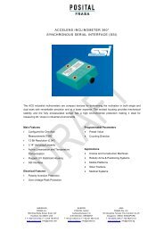
PS5R Slim Line<br />
PS5R Slim Line Series<br />
Switching <strong>Power</strong> <strong>Supplies</strong><br />
Key features:<br />
• Lightweight and compact in size<br />
• Wide power range: 10W-240W<br />
• Universal input:<br />
10W to 90W: 85-264V AC/100-370V DC<br />
120W and 240W: 85-264V AC/100-350V DC<br />
• <strong>Power</strong> Factor Correction for 60W to 240W<br />
(EN61000-3-2)<br />
• Meets SEMI F47 Sag Immunity (120W & 240W only)<br />
• UL Listed for Class 1, Div. 2 Hazardous Locations<br />
• Overcurrent protection, auto-reset<br />
• Overvoltage protection, shut down<br />
• Spring-up screw terminal type, IP20<br />
• DIN rail or panel surface mount<br />
• Approvals:<br />
CE Marked<br />
ANSI/ISA-12.12.01-2011 (Hazardous locations)<br />
TÜV<br />
EN50178:1997<br />
c-UL, UL508<br />
LVD: EN60950:2000<br />
UL1310 (PS5R-SB, -SC, -SD) EMC: Directive EN61204-3:2000 (EMI: Class B, EMS: Industrial)<br />
DC Low Indicator<br />
(15W, 120W & 240W Slim Line Only)<br />
The indicator turns on when the output<br />
voltage drops below 80% of the rated value.<br />
This assists in troubleshooting power supply<br />
problems.<br />
DC ON Indicator<br />
The indicator turns on when the unit is powered<br />
up. This is a convenient way to know when the<br />
power supply is receiving power.<br />
Output Voltage Adjustment<br />
The output voltage can be easily adjusted within<br />
+ 10% of the rated voltage.<br />
Fingersafe, Spring-up Screw Terminals<br />
Don’t worry about losing screws or getting an<br />
inadvertent shock from a terminal. The terminals are<br />
captive spring-up screws, which makes using them as easy as<br />
pushing a screw down and tightening it.<br />
They are shock and vibration resistant, and work with ring lugs,<br />
fork connectors or stripped wire connections. The terminals are<br />
rated IP20 (when tightened) meaning they are recessed to keep<br />
fingers and objects from touching the input contacts.<br />
File #E234997<br />
Designed with Accessibility & Convenience in Mind!<br />
Top<br />
View<br />
(SEMI F47 120W &<br />
240W only)<br />
Universal Input <strong>Power</strong><br />
The applied input power has a range of 85-264V<br />
AC (100-350V DC) without the use of jumpers or<br />
slide switches. This makes IDEC power supplies<br />
suitable for use anywhere in the world.<br />
Long Life Expectancy<br />
IDEC power supplies are very reliable, with a life<br />
expectancy of 70,000 hrs. (minimum) or longer,<br />
depending on usage. <strong>Power</strong> factor correction has<br />
also been included to minimize harmonic distortion,<br />
resulting in a longer operating life and increased<br />
reliability.<br />
Output Channel<br />
With very low output ripples of less than 1% peak<br />
to peak, the 120W and 240W power supplies are<br />
some of the best in the industry. The output comes<br />
with overload protection that avoids damaging the<br />
power supply and the spring-up, fingersafe, screw<br />
terminals add a level of safety and ease for the<br />
user. The 240W power supply also has the convenience<br />
of two output terminals.<br />
Ventilation Grill<br />
Provides cooling for<br />
the power supply and<br />
prevents small objects<br />
from falling into the<br />
power supply circuitry.<br />
OI Touchscreens PLCs Automation Software <strong>Power</strong> <strong>Supplies</strong> Sensors Communication Barriers<br />
800-262-IDEC (4332) • USA & Canada<br />
141
PS5R Slim Line<br />
<strong>Power</strong> <strong>Supplies</strong><br />
Part Numbers<br />
OI Touchscreens<br />
Style<br />
Watts<br />
Rated<br />
Voltage<br />
Rated<br />
Current<br />
Part<br />
Number<br />
Style<br />
Watts<br />
Rated<br />
Voltage<br />
Rated<br />
Current<br />
Part<br />
Number<br />
10 5V DC 2.0A PS5R-SB05<br />
90 24V DC 3.75A PS5R-SE24<br />
12V DC 1.2A PS5R-SB12<br />
PLCs<br />
15<br />
24V DC 0.65A PS5R-SB24<br />
12V DC 2.5A PS5R-SC12<br />
Automation Software<br />
30<br />
24V DC 1.3A PS5R-SC24<br />
120 24V DC 5A PS5R-SF24<br />
<strong>Power</strong> <strong>Supplies</strong><br />
60 24V DC 2.5A PS5R-SD24<br />
240 24V DC 10A PS5R-SG24<br />
Sensors<br />
Accessories<br />
Appearance Description Part Number<br />
Panel Mounting Bracket for PS5R-SB<br />
Panel Mounting Bracket for PS5R-SB (flat side mounting)<br />
PS9Z-5R1B<br />
PS9Z-5R2B<br />
Communication<br />
Panel Mounting Bracket for PS5R-SC and PS5R-SD<br />
Panel Mounting Bracket for PS5R-SE<br />
Panel Mounting Bracket for PS5R-SF & PS5R-SG<br />
PS9Z-5R1C<br />
PS9Z-5R1E<br />
PS9Z-5R1G<br />
DIN rail (1000mm)<br />
BNDN1000<br />
Barriers<br />
DIN rail end clip<br />
BNL5<br />
142 www.IDEC.com
<strong>Power</strong> <strong>Supplies</strong><br />
PS5R Slim Line<br />
Model<br />
Specifications<br />
5V DC output PS5R-SB05 – – – – –<br />
12V DC output PS5R-SB12 PS5R-SC12 – – – –<br />
24V DC output PS5R-SB24 PS5R-SC24 PS5R-SD24 PS5R-SE24 PS5R-SF24 PS5R-SG24<br />
Output Capacity 15W (5V Model is 10W) 30W 60W 90W 120W 240W<br />
Input<br />
Output<br />
Input Voltage<br />
(single-phase, 2-wire)<br />
85 to 264V AC,<br />
100 to 370V DC<br />
85 to 264V AC,<br />
100 to 350V DC<br />
Input Current 100VAC 0.45A 0.9A 1.7A 2.3A 1.8A 3.5A<br />
(maximum) 200VAC 0.3A 0.6A 1.0A 1.4A 1.0A 1.7A<br />
Internal Fuse Rating 2A 3.15A 4A 6.3A<br />
Inrush Current (cold start)<br />
50A maximum (at 200V AC)<br />
Leakage Current (at no load)<br />
132V AC: 0.38 mA maximum<br />
264V AC: 0.75 mA maximum<br />
0.75mA maximum<br />
1mA maximum<br />
5V DC 69% – – – – –<br />
Typical<br />
Efficiency<br />
12V DC 75% 78% – – – –<br />
24V DC 79% 80% 83% 82% 84%<br />
5V DC 2.0A – – – – –<br />
Output Current<br />
Ratings<br />
12V DC 1.2A 2.5A – – – –<br />
24V DC 0.65A 1.3A 2.5A 3.75A 5A 10A<br />
Voltage Adjustment<br />
±10% (V. ADJ control on front)<br />
Output Holding Time<br />
20ms minimum (at rated input and output)<br />
Starting Time 200ms maximum – – – 650ms maximum 500ms maximum<br />
Rise Time 100ms maximum (at rated input and output) 200ms maximum<br />
Line Regulation<br />
0.4% maximum<br />
Load Regulation 1.5% maximum 0.8% max<br />
Temperature Regulation<br />
0.05% degree C maximum<br />
Ripple Voltage 2% peak to peak maximum (including noise) 1% peak to peak maximum (including noise)<br />
Overcurrent Protection 105% or more, auto reset 105 to 130%, auto reset 103 to 110%, auto reset<br />
Overvoltage Protection<br />
120% min. SHUTDOWN<br />
Operation Indicator<br />
LED (green)<br />
Voltage Low Indication LED (amber) – – – LED (amber)<br />
Between Input and Ground: 2000 V AC, 1 minute<br />
Dielectric Strength<br />
Between input and output: 3000V AC, 1 minute;<br />
Between output and ground: 500V AC, 1 minute.<br />
Insulation Resistance<br />
Between Input & Output Terminals: 100 MΩ Min<br />
Operating Temperature –10 to +65°C (14 to 149°F) -10 to 60°C (14 to 140°F)<br />
Storage Temperature<br />
-25 to 75°C (-13 to +167°F)<br />
Operating Humidity<br />
20 to 90% relative humidity (no condensation)<br />
Vibration Resistance<br />
Frequency 10 to 55Hz, Amplitude 0.375mm<br />
Shock Resistance<br />
300m/s 2 (30G) 3 times each in 6 axes<br />
EMC: EN61204-3 (EMI: Class B, EMS: Industrial), c-UL (CSA 22.2 No. 14), ANSI/ISA-12.12.01-2011, UL508, LVD: EN60950, EN50178<br />
Approvals<br />
UL1310 Class 2, c-UL (CSA 22.2 No. 213 and 223) – SEMI F47<br />
Harmonic Directive N/A EN61000-3-2 A14 class A<br />
Weight (approx.) 160g 250g 285g 440g 630g 1000g<br />
Terminal Screw<br />
M3.5 slotted-Phillips head screw (screw terminal type)<br />
IP protection<br />
IP20 fingersafe<br />
Dimensions H x W x D (mm) 90 x 22.5 x 95 95 x 36 x 108 115 x 46 x 121 115 x 50 x 129 125 x 80 x 149.5<br />
Dimensions H x W x D (inches) 3.54 x 0.89 x 3.74 3.74 x 1.42 x 4.25 4.53 x 1.81 x 4.76 4.53 x 1.97 x 5.08 4.92 x 3.15 x 5.89<br />
1. For dimensions, see page 145.<br />
OI Touchscreens PLCs Automation Software <strong>Power</strong> <strong>Supplies</strong> Sensors Communication Barriers<br />
800-262-IDEC (4332) • USA & Canada<br />
143
PS5R Slim Line<br />
<strong>Power</strong> <strong>Supplies</strong><br />
Temperature Derating Curves<br />
<strong>Power</strong> <strong>Supplies</strong><br />
Automation Software<br />
PLCs<br />
OI Touchscreens<br />
All IDEC Slim Line power supplies are listed to UL508, which allows operation<br />
at 100% capacity inside a panel. This eliminates the need to use oversize power<br />
supplies or utilize two power supplies derated at 50% of their rated output.<br />
PS5R-SB<br />
Output Current (%)<br />
100<br />
Mounting A<br />
90<br />
80<br />
Mounting B, C, D<br />
70<br />
60<br />
50<br />
40<br />
30<br />
20<br />
10<br />
0<br />
–10 0 10 20 30 40 50 55 60 65 70<br />
Operating Temperature (°C)<br />
Dearting curve for PS5R-SB varies depending on<br />
mounting method (see right).<br />
PS5R-SD, -SE, -SF<br />
100<br />
90<br />
80<br />
70<br />
60<br />
50<br />
40<br />
30<br />
20<br />
10<br />
0<br />
-10 0 10 20 30 40 50 60 70<br />
Operating Temperature (ºC)<br />
Output Cuurent (%)<br />
Mounting A<br />
(standard)<br />
Mounting C<br />
(left side up)<br />
Mounting B<br />
(upright)<br />
Mounting D<br />
(right side up)<br />
PS5R-SC<br />
The charts below show that the PS5R Slim 10W (at 60ºC) and 15W (at 60ºC),<br />
30W/60W/90W (at 55ºC), 120W (at 40ºC), and 240W (at 45ºC) meet the<br />
elevated, operating temperature required by UL508 and EN60950 standards to<br />
operate at an output current of 100%. The output current starts to derate beyond<br />
the required temperature.<br />
100<br />
90<br />
80<br />
70<br />
60<br />
50<br />
40<br />
30<br />
20<br />
10<br />
0<br />
-10 0 10 20 30 40 50 55 60 70<br />
Operating Temperature (ºC)<br />
Output Cuurent (%)<br />
PS5R-SG<br />
PS5R-SE 90W/3.75A/24V DC versus a Leading Competitor<br />
Standard derating curve (operating temperature vs. output current)<br />
Don’t Believe the Hype<br />
Currrent (A)<br />
4.0<br />
3.0<br />
2.0<br />
1.0<br />
“Boost” Rating 3.75A<br />
“Normal” Rating 2.5A<br />
Leading Competitor<br />
“24V/2.5A”<br />
100<br />
90<br />
80<br />
70<br />
60<br />
50<br />
40<br />
30<br />
20<br />
10<br />
0<br />
-10 0 10 20 30 40 45 50 60 70<br />
Operating Temperature (ºC)<br />
Output Cuurent (%)<br />
Other companies use slick marketing to sell you 60W power<br />
supplies with a “BOOST,” but what they don’t tell you is that<br />
these are merely 90W power supplies that have been renamed<br />
to fool you into thinking they have a unique feature. IDEC 90W<br />
power supplies are just what they claim, 90W power supplies.<br />
The truth is IDEC led the market by incorporating UL508 DIN rail<br />
mount power supplies as a standard product. Don’t let the other<br />
guys pull a fast one on you by claiming to provide features that<br />
just aren’t true, or even possible. See what IDEC has to offer, no<br />
strings attached.<br />
Sensors<br />
Communication<br />
Barriers<br />
24<br />
Overload Protection<br />
Overload protection prevents the power supply from being damaged when an overload occurs. There are two kinds of protection.<br />
Overcurrent Protection<br />
Overvoltage Protection<br />
Overcurrent Protection<br />
PS5R-SF, -SG<br />
When the output current exceeds<br />
105% of the rated current, overload<br />
protection is triggered, and the<br />
output voltage starts decreasing.<br />
When the output current returns<br />
within the rated range, the overload<br />
protection function is automatically<br />
cleared.<br />
SEMI-F47 Approved<br />
Overvoltage Protection<br />
When the output voltage of the<br />
power supply rises to 120% or more<br />
of the rated value, the output will<br />
shut off. To restore power, only<br />
manual reset is available which is an<br />
advantage in troubleshooting.<br />
The SEMI F47 (Semiconductor Processing Equipment Voltage Sag Immunity) defines the minimum voltage sag<br />
ride-through requirements for semiconductor processing, automated test equipment and other equipment. It<br />
requires that the equipment be able to tolerate voltage sags on an AC power line without interrupting operations.<br />
This avoids the loss of production and money.<br />
The graph shows how the equipment must tolerate sags to 50% for 200ms, sags to 70% for up to 0.5 seconds<br />
and sags to 80% for up to 1 second.<br />
Voltage Sag Sliding Scale PS5R-SF, -SG<br />
144 www.IDEC.com
<strong>Power</strong> <strong>Supplies</strong><br />
PS5R Slim Line<br />
Dimensions and Terminal Markings<br />
PS5R-SB<br />
Height<br />
Width<br />
Depth<br />
90mm<br />
22.5mm<br />
95mm<br />
Front Panel (terminals)<br />
INPUT<br />
100-240VAC<br />
LOW<br />
ON<br />
VR.<br />
ADJ<br />
OUTPUT<br />
PS5R-SF<br />
Height<br />
Width<br />
Depth<br />
115.0mm<br />
50.0mm<br />
129.0mm<br />
Markings Name Description<br />
PS5R-SC<br />
PS5R-SD<br />
Height<br />
Width<br />
Depth<br />
95.0mm<br />
36.0mm<br />
108.0mm<br />
V. ADJ Voltage adjustment<br />
Adjusts within ±10%; turn clockwise to<br />
increase output voltage.<br />
DC ON Operation indicator Green LED is lit when output voltage is on.<br />
DC Low Output indicator<br />
Amber LED is lit when output voltage drops<br />
below 80% of rated voltage.<br />
+V, –V DC output terminals<br />
+V: Positive output Terminal<br />
–V: Negative output terminal<br />
Frame ground<br />
Ground this terminal to reduce high-frequency<br />
noise caused by switching power supply.<br />
L, N Input terminals<br />
Accept a wide range of voltages and frequencies<br />
(no polarity at DC input).<br />
L N<br />
INPUT 50/60Hz<br />
DC ON<br />
VR.<br />
ADJ<br />
OUTPUT<br />
-V<br />
+V<br />
PS5R-SE<br />
Height<br />
Width<br />
Depth<br />
PS5R-SG<br />
Height<br />
Width<br />
Depth<br />
115.0mm<br />
46.0mm<br />
121.0mm<br />
125.0 mm<br />
80.0 mm<br />
149.5 mm<br />
L N<br />
INPUT 50/60Hz<br />
DC ON<br />
VR.<br />
ADJ<br />
OUTPUT<br />
-V<br />
80<br />
+V<br />
125<br />
149.5<br />
OI Touchscreens PLCs Automation Software <strong>Power</strong> <strong>Supplies</strong> Sensors Communication Barriers<br />
800-262-IDEC (4332) • USA & Canada<br />
145
PS5R Slim Line<br />
<strong>Power</strong> <strong>Supplies</strong><br />
Mounting Bracket Dimensions (mm)<br />
OI Touchscreens<br />
PS9Z-5R1B (for PS5R-SB) PS9Z-5R2B (for PS5R-SB) PS9Z-5R1C (for PS5R-SC & PS5R-SD)<br />
PS9Z-5R1B<br />
PS9Z-5R2B<br />
PLCs<br />
12<br />
24.7<br />
2-M4 tapped holes or 2-ø4.5 through holes<br />
Barriers<br />
Communication<br />
Sensors<br />
120<br />
112<br />
Automation Software<br />
<strong>Power</strong> <strong>Supplies</strong><br />
62.9<br />
44<br />
115<br />
105<br />
102<br />
110<br />
2-M4 tapped holes or 2-ø4.5 through holes<br />
(See the front page for mounting examples.)<br />
26<br />
38<br />
2-M4 Tapped Holes or<br />
2-ø4.5 Drilled Holes<br />
PS9Z-5R1E (for PS5R-SE)<br />
135<br />
125<br />
PS9Z-5R1G (for PS5R-SF & PS5R-SG)<br />
145<br />
135<br />
36<br />
48<br />
2-M4 Tapped Holes or<br />
2-ø4.5 Drilled Holes<br />
36<br />
48<br />
4-M4 Tapped Holes or<br />
4-ø4.5 Drilled Holes<br />
146 www.IDEC.com
<strong>Power</strong> <strong>Supplies</strong><br />
PS5R Standard Series<br />
Key features:<br />
• Wide power range: 7.5W-240W<br />
• Universal input :<br />
7.5W-50W: 85-264V AC/105-370V DC<br />
100W: 85-132V AC/170-264V AC<br />
240-370V DC (selectable)<br />
75W, 120W, 240W: 85-264V AC/110-350V DC<br />
• Overcurrent/overvoltage protection<br />
• <strong>Power</strong> Factor Correction (75W, 120W, 240W models)<br />
EN61000-3-3<br />
EN61000-3-2<br />
• Voltage adjustment +10%<br />
• Spring-up crew terminal, IP20 (finger-safe)<br />
• DIN rail or panel surface mount<br />
• Approvals:<br />
CE marked<br />
UL 508 Listed<br />
c-UL<br />
TÜV approved<br />
EMC Directives:<br />
EN50081-2<br />
EN50082-2<br />
EN61000-6-2<br />
LVD EN60950:2000<br />
Style<br />
Watts<br />
7.5<br />
15<br />
30<br />
Rated<br />
Voltage<br />
Rated<br />
Current<br />
PS5R Standard Series<br />
Switching <strong>Power</strong> <strong>Supplies</strong><br />
Part<br />
Number<br />
5V DC 1.5A PS5R-A05<br />
12V DC 0.6A PS5R-A12<br />
24V DC 0.3A PS5R-A24<br />
5V DC 2.5A PS5R-B05<br />
12V DC 1.2A PS5R-B12<br />
24V DC 0.6A PS5R-B24<br />
12V DC 2.5A PS5R-C12<br />
24V DC 1.3A PS5R-C24<br />
50 24V DC 2.1A PS5R-D24<br />
Part Numbers<br />
Style<br />
UL 508 Listed<br />
File #E177168<br />
Cert No.<br />
BL980213332392<br />
Watts<br />
Rated<br />
Voltage<br />
Rated<br />
Current<br />
Part<br />
Number<br />
75 24V DC 3.1A PS5R-Q24<br />
100 24V DC 4.2A PS5R-E24<br />
120 24V DC 5A PS5R-F24<br />
240 24V DC 10A PS5R-G24<br />
OI Touchscreens PLCs Automation Software <strong>Power</strong> <strong>Supplies</strong> Sensors Communication Barriers<br />
800-262-IDEC (4332) • USA & Canada<br />
147
PS5R Standard Series<br />
<strong>Power</strong> <strong>Supplies</strong><br />
Specifications<br />
Barriers<br />
Communication<br />
Sensors<br />
<strong>Power</strong> <strong>Supplies</strong><br />
Automation Software<br />
PLCs<br />
OI Touchscreens<br />
Model<br />
PS5R-A05 PS5R-B05* — — — —<br />
PS5R-A12 PS5R-B12 PS5R-C12 — — —<br />
PS5R-A24 PS5R-B24 PS5R-C24 PS5R-D24 PS5R-Q24 PS5R-E24 PS5R-F24 PS5R-G24<br />
Output Capacity 7.5W 15W 30W 50W 75W 100W 120W 240W<br />
Input<br />
Output<br />
Input Voltage (singlephase,<br />
2-wire)<br />
Input Current (typical)<br />
100 to 240V AC nominal (85 to 264V AC), 50/60Hz (47 to 63Hz)<br />
110 to 340V DC nominal (105 to 370V DC)<br />
0.17A at<br />
100V AC<br />
0.3A at<br />
100V AC<br />
0.68A at<br />
100V AC<br />
1.15A at<br />
100V AC<br />
1.1A at<br />
100V AC<br />
100 to 120V AC,<br />
50/60Hz<br />
200 to 240V AC,<br />
50/60Hz<br />
(jumper selectable)<br />
240 to 370V DC<br />
2.5A at 100V AC<br />
1.5A at 200V AC<br />
100 to 240V AC, 50/60Hz,<br />
110 to 340V DC<br />
1.8A at<br />
100V AC<br />
Internal Fuse Rating 2A 2A 3.15A 3.15A 3.15A 4A 4A 6.3A<br />
Inrush Current<br />
Leakage Current (at<br />
no load)<br />
Typical Efficiency<br />
Overvoltage Protection<br />
Voltage and Current<br />
Ratings<br />
50A maximum (at cold start at 200V AC)<br />
5V, 1.5A<br />
12V, 0.6A<br />
24V, 0.3A<br />
69% at 5V<br />
75% at 12V<br />
79% at 24V<br />
5V, 2.5A<br />
12V, 1.2A<br />
24V, 0.6A<br />
70A maximum<br />
(at cold start at<br />
230V AC)<br />
50A maximum (at<br />
cold start at 200V<br />
AC)<br />
0.75mA maximum (60Hz, measured in conformance with UL, CSA, VDE)<br />
75% at 12V<br />
75% at 24V<br />
12V, 2.5A<br />
24V, 1.3A<br />
4A at 100V AC<br />
70A maximum (at cold start at<br />
230V AC)<br />
79% at 24V 83% at 24V 85% at 24V 83% at 24V<br />
Outputs turns off at 105% (typical)<br />
24V, 2.1A 24V, 3.1A 24V, 4.2A 24V, 5A 24V, 10A<br />
Voltage Adjustments<br />
±10% (V.ADJ screw on top)<br />
Output Holding Time<br />
20ms minimum (at full rated input and output)<br />
Rise Time 200ms maximum (at full rated input and output) 150ms max.<br />
Line Regulation<br />
0.4% maximum<br />
Load Regulation<br />
1.5% maximum<br />
Fluctuation due to<br />
Ambient Temperature<br />
0.05% maximum<br />
Change<br />
Ripple Voltage<br />
2% peak to peak maximum (including noise)<br />
Overload Protection 120% typical (Zener-limiting) 120% typical, auto reset<br />
Operation Indicator<br />
LED (green)<br />
Parallel Operation<br />
PS5R-A PS5R-B PS5R-C PS5R-D PS5R-Q PS5R-E PS5R-F PS5R-G<br />
Allowed<br />
No Yes No Yes<br />
Between input and output terminals: 3,000V AC, 1 minute<br />
Dielectric Strength<br />
Between input terminals and housing: 2,000V AC, 1 minute<br />
Between output terminal and housing: 500V AC, 1 minute<br />
Insulation Resistance<br />
Between input and output terminals/input terminals and housing: 100MΩ minimum (500V DC megger)<br />
Operating Temperature<br />
–10˚ to +60˚C (14˚ to 140˚F) (see derating curves)<br />
Storage Temperature<br />
–30˚ to +85˚C (-22˚ to 185˚F)<br />
Operating Humidity<br />
20 to 90% relative humidity (no condensation)<br />
Vibration Resistance 45m/s 2 , 10 to 55Hz, 2 hours on each of 3 axes 10 to 50Hz, 0.75mm p-p, 2 hrs on each of 3 axes<br />
Shock Resistance<br />
300m/s 2 (30G), 3 shocks in each of 6 directions<br />
Approvals<br />
Conforms to EMC Directives EN50081-2 & EN50082-2. LVD Directive EN60529 — Certified to EN60950.<br />
UL508 listed. c-UL, TUV approved. CE marked. EN61000-3-2<br />
Weight 150g 170g 360g 390g 800g 600g 1200g 2000g<br />
Termination<br />
Spring-up, fingersafe terminals with captive M3.5 screws<br />
IP protection<br />
IP20 (finger safe)<br />
Dimensions H x W x D (mm) 75 x 45 x 70 75 x 45 x95 75 x 90 x 95 75 x 90 x 95 120 x 85 x 140 75 x 145 x 95 120 x 115 x140 120 x 200x 140<br />
Dimensions H x W x D<br />
(inches)<br />
2.95 x 1.77 x<br />
2.76<br />
1. For dimensions, see page 151.<br />
2. For usage instructions, see page 150.<br />
2.95 x 1.77 x<br />
3.74<br />
3. *12.5W for 5VDC model.<br />
2.95 x 3.54 x<br />
3.74<br />
2.95 x 3.54 x<br />
3.74<br />
4.72 x 3.35 x<br />
5.52<br />
2.95 x 5.71 x 3.74<br />
4.72 x 4.53 x<br />
5.52<br />
4.72 x 7.87 x<br />
5.51<br />
148 www.IDEC.com
<strong>Power</strong> <strong>Supplies</strong><br />
PS5R Standard Series<br />
PS5R-A/B<br />
Output Current (%)<br />
Mounting style B<br />
100<br />
90<br />
Mounting style A<br />
80<br />
70<br />
60<br />
50<br />
40<br />
30<br />
20<br />
10<br />
0<br />
–10 0 10 20 30 40 50 60<br />
Operating Temperature (C)<br />
PS5R-E<br />
Output Current (%)<br />
100<br />
90<br />
80<br />
70<br />
60<br />
50<br />
40<br />
30<br />
20<br />
10<br />
0<br />
-10<br />
PS5R-F/G<br />
Output Current (%)<br />
Mounting style B<br />
Mounting style A<br />
0 10 20 30 40 50 60<br />
Operating Temperature (°C)<br />
100<br />
90<br />
80<br />
70<br />
60<br />
50<br />
40<br />
30<br />
20<br />
10<br />
0<br />
0 10 20 30 35 40 50 60<br />
Operating Temperature (C)<br />
Temperature Derating Curves<br />
PS5R-C/D<br />
Output Current (%)<br />
Mounting style B<br />
100<br />
90<br />
Mounting style A<br />
80<br />
70<br />
60<br />
50<br />
40<br />
30<br />
20<br />
10<br />
0<br />
–10 0 10 20 30 35 40 50 60<br />
Operating Temperature (C)<br />
PS5R-Q<br />
Mounting Style B<br />
A Mounting (standard)<br />
Mounting Style A<br />
Output Current (%)<br />
Mounting style B<br />
Mouting style A<br />
100<br />
90<br />
80<br />
70<br />
60<br />
50<br />
40<br />
30<br />
20<br />
10<br />
0<br />
0 10 20 30 40 50 60<br />
Operating Temperature (C)<br />
Vertical<br />
B Mounting (Facing Upward)<br />
Vertical<br />
OI Touchscreens PLCs Automation Software <strong>Power</strong> <strong>Supplies</strong> Sensors Communication Barriers<br />
800-262-IDEC (4332) • USA & Canada<br />
149
PS5R Standard Series<br />
<strong>Power</strong> <strong>Supplies</strong><br />
OI Touchscreens<br />
Accessories<br />
Part Numbers: PS5R Accessories<br />
Appearance Description Part Number<br />
DIN rail (1000mm) BNDN1000<br />
Overcurrent Protection Characteristics<br />
PS5R-A/B<br />
Output Voltage (%)<br />
100<br />
50<br />
PLCs<br />
DIN rail end clip<br />
BNL5<br />
0<br />
Output Current (%)<br />
100105<br />
Installation Instructions<br />
PS5R-C/D/E<br />
Time-Saving Spring-up Terminals<br />
100<br />
Automation Software<br />
The innovative terminals on the PS5R series use a spring-loaded screw. This<br />
makes installation as easy as pushing down and turning with a screwdriver. Installation<br />
time is cut in half since the screws do not need to be backed out to install<br />
wiring. The screws are held captive once installed and are 100% finger-safe.<br />
Screw terminals accept bare wire or ring or fork connectors.<br />
1. Insert the wire connector into the slot on the side of the power supply.<br />
Output Voltage (%)<br />
50<br />
0<br />
Output Current (%)<br />
100 105<br />
<strong>Power</strong> <strong>Supplies</strong><br />
Sensors<br />
Communication<br />
2. Using a flat head or Phillips screwdriver, push down and turn<br />
the screw.<br />
The wire is now connected, and the screw terminal is fingersafe!<br />
Front Panel (terminals)<br />
Markings Name Description<br />
V. ADJ<br />
DC ON<br />
+V, –V<br />
L, N<br />
NC<br />
Voltage<br />
adjustment<br />
Operation<br />
indicator<br />
DC output<br />
terminals<br />
Frame<br />
ground<br />
Input<br />
terminals<br />
No connection<br />
Adjusts within ±10%; turn clockwise<br />
to increase output voltage<br />
Green LED is lit when output voltage<br />
is on<br />
+V: Positive output Terminal<br />
–V: Negative output terminal<br />
Ground this terminal to reduce<br />
high-frequency currents caused by<br />
switching<br />
Accept a wide range of voltages and<br />
frequencies (no polarity at DC input)<br />
Do not insert wires here, as this may<br />
damage the power supply<br />
PS5R<br />
PS5R<br />
+<br />
-<br />
PS5R<br />
PS5R<br />
PS5R<br />
Parallel Operation<br />
Barriers<br />
TERMINALS<br />
ELECTRICAL LOAD<br />
1. Parallel operation only recommended for PS5R-Q24, PS5R-F24 and PS5R-G24.<br />
2. Factory recommended diode ST Microelectronics BYV54V-50, BYV54V-100,<br />
BYV54V-200, BYV541V-200 or with equivalent electrical specifications.<br />
3. Using the voltage adjustment make sure out-voltage is the same for all power<br />
supplies.<br />
150 www.IDEC.com
<strong>Power</strong> <strong>Supplies</strong><br />
PS5R Standard Series<br />
62.5<br />
60<br />
R2.25<br />
6-ø6.5<br />
DC ON<br />
V.ADJ<br />
M3.5 Terminal Screws<br />
12<br />
35<br />
38.5<br />
75<br />
60<br />
5<br />
7.35<br />
75<br />
12<br />
M3.5 Terminal<br />
Screws<br />
145<br />
135<br />
200-240V<br />
4-ø4.5<br />
Dimensions<br />
PS5R-A (7.5W) PS5R-B (15W) PS5R-C (30W)<br />
10-ø6.5<br />
4-ø4.5<br />
DC ON<br />
V.ADJ<br />
M3.5 Terminal<br />
Screws<br />
90<br />
13<br />
80<br />
13 13 13<br />
12<br />
7.35<br />
60<br />
75<br />
5<br />
62.5<br />
60<br />
R2.25<br />
6-ø6.5<br />
DC ON<br />
V.ADJ<br />
M3.5 Terminal<br />
Screws<br />
12<br />
35<br />
38.5<br />
13 13 13 M3.5 Terminal Screws<br />
75<br />
85<br />
7.35<br />
75<br />
101<br />
110<br />
120<br />
4.6<br />
13 13 26 13 13<br />
190<br />
200<br />
10-ø6.5<br />
4-ø4.5<br />
DC ON<br />
V.ADJ<br />
13<br />
M3.5 Terminal<br />
Screws<br />
PS5R-D (50W) PS5R-Q (75W) PS5R-F (120W)<br />
PS5R-E (100W)<br />
4-ø4.5<br />
14-ø6.5<br />
4-ø4.5<br />
Terminal Markings<br />
PS5R-A/B PS5R-C/D/Q/F/G PS5R-E<br />
DC ON<br />
V.ADJ<br />
NC<br />
-V +V<br />
INPUT<br />
L<br />
N<br />
NC<br />
–V +V<br />
DC ON<br />
V.ADJ<br />
NC<br />
INPUT<br />
L<br />
N<br />
NC<br />
PS5R-G (240W)<br />
DC ON<br />
V.ADJ<br />
4-ø4.5<br />
13 13<br />
102<br />
110<br />
120<br />
90<br />
80<br />
13 13<br />
16 13 13<br />
105<br />
115<br />
M3.5 Terminal<br />
Screws<br />
–V +V<br />
100w-OUTPUT<br />
INPUT<br />
VOLTAGE SELECT<br />
L N<br />
200-240V 100-120V<br />
13<br />
12<br />
7.35<br />
101<br />
110<br />
120<br />
60<br />
75<br />
5<br />
M3.5 Terminal<br />
Screws<br />
OI Touchscreens PLCs Automation Software <strong>Power</strong> <strong>Supplies</strong> Sensors Communication Barriers<br />
200-240V<br />
800-262-IDEC (4332) • USA & Canada<br />
151
PS3X<br />
<strong>Power</strong> <strong>Supplies</strong><br />
PS3X Series<br />
OI Touchscreens<br />
Key features:<br />
• Compact size<br />
• Universal AC input voltage<br />
• 5V, 12V and 24V DC outputs<br />
• Available with mounting brackets for direct or DIN rail mounting<br />
• Overcurrent/overvoltage protection<br />
• EMC, EN55022 Class B compliant<br />
• UL/c-UL recognized, TUV<br />
PLCs<br />
Part Numbers<br />
Automation Software<br />
<strong>Power</strong> Supply<br />
Style<br />
Output<br />
Capacity<br />
15W<br />
Part Number<br />
PS3X-B05AFC<br />
PS3X-B12AFC<br />
PS3X-B24AFC<br />
Input<br />
Voltage<br />
Output<br />
Voltage<br />
5V<br />
12V<br />
24V<br />
Output<br />
Current<br />
3.0A<br />
1.3A<br />
0.63A<br />
L-shaped Mounting Bracket (optional)<br />
Applicable <strong>Power</strong> Supply Part Number<br />
PS3X-B<br />
PS9Z-3N3A<br />
PS3X-C<br />
PS9Z-3N3B<br />
PS3X-D<br />
PS9Z-3E3B<br />
PS3X-Q<br />
PS3X-E<br />
PS9Z-3N3E<br />
<strong>Power</strong> <strong>Supplies</strong><br />
25W<br />
50W<br />
PS3X-C05AFC<br />
PS3X-C12AFC<br />
PS3X-C24AFC<br />
PS3X-D12AFG<br />
PS3X-D24AFG<br />
100 to<br />
240V AC<br />
5V<br />
12V<br />
24V<br />
12V<br />
24V<br />
5.0A<br />
2.1A<br />
1.1A<br />
4.2A<br />
2.2A<br />
DIN-rail Mounting Bracket (optional)<br />
Applicable <strong>Power</strong> Supply Part Number<br />
PS3X-B<br />
PS3X-C<br />
PS9Z-3N4B<br />
PS3X-D<br />
PS9Z-3E4C<br />
PS3X-Q<br />
PS3X-E<br />
PS9Z-3E4D<br />
DIN Rail<br />
75W<br />
PS3X-Q05AFG<br />
PS3X-Q12AFG<br />
PS3X-Q24AFG<br />
5V<br />
12V<br />
24V<br />
12.0A<br />
6.0A<br />
3.2A<br />
Appearance Part Number Length Material Weight (g)<br />
Sensors<br />
100W<br />
PS3X-E05AFG<br />
PS3X-E12AFG<br />
PS3X-E24AFG<br />
5V<br />
12V<br />
24V<br />
16.0A<br />
8.5A<br />
4.5A<br />
End Clips<br />
BNDN1000 1000mm Aluminum 200<br />
Appearance Part Number Description<br />
BNL5<br />
small DIN rail end clip<br />
Communication<br />
Barriers<br />
Part Number Configuration<br />
PS3X - B 05 AF C<br />
Output Capacity<br />
B: 15W<br />
C: 25W<br />
D: 50W<br />
Q: 75W<br />
E: 100W<br />
Output Voltage<br />
05: 5V DC (15W, 25W, 75W, 100W)<br />
12: 12V DC<br />
24: 24V DC<br />
Cover and Terminal Style<br />
C: w/Standard cover,<br />
Horizontal terminal block<br />
(PS3X-B/C models)<br />
G: w/Standard cover,<br />
Vertical terminal block<br />
(PS3X-D/Q/E models)<br />
Input Voltage<br />
AF: 100 to 240V AC<br />
BNL6<br />
medium DIN rail end clip (the BNL6 has a<br />
higher profile than BNL5)<br />
152 www.IDEC.com
<strong>Power</strong> <strong>Supplies</strong><br />
PS3X<br />
Model<br />
Input<br />
Output<br />
Supplementary<br />
Functions<br />
Dielectric<br />
Strength<br />
Specifications<br />
[15W]<br />
PS3X-B05/B12/B24<br />
[25W]<br />
PS3X-C05/C12/C24<br />
[50W]<br />
PS3X-D12/D24<br />
[75W]<br />
PS3X-Q05/Q12/Q24<br />
[100W]<br />
PS3X-E05/E12/E24<br />
Rated Input Voltage<br />
100 to 240V AC<br />
Voltage Range (Note 1)<br />
85 to 264V AC/<br />
120 to 375V DC<br />
88 to 264V AC / 125 to 375V DC<br />
Frequency<br />
47 to 63 Hz<br />
Input Current 0.5A max. 0.65A max. 1.3A max. 1.8A max. 2.5A max.<br />
Inrush Current at 115V AC 40A max. 30A max. 30A max. 30A max. 35A max.<br />
(Ta = –25°C,<br />
ACV cold start)<br />
at 230V AC 60A max. 50A max. 50A max. 50A max. 70A max.<br />
Leakage Current 0.5mA max. 1.5mA max. 1.5mA max. 1.5mA max. 1.5mA max.<br />
Efficiency (Typ.)<br />
(230V AC at input/<br />
rated output)<br />
Rated Voltage/Current<br />
5V 77% 77% — 77% 77%<br />
12V 81% 81% 81% 82% 81%<br />
24V 82% 84% 84% 84% 84%<br />
5V, 3A 5V, 5A — 5V, 12A 5V, 16A<br />
12V, 1.3A 12V, 2.1A 12V, 4.2A 12V, 6A 12V, 8.5A<br />
24V, 0.63A 24V, 1.1A 24V, 2.2A 24V, 3.2A 24V, 4.5A<br />
Adjustable Voltage Range ±10%<br />
Output Holding Time<br />
13 ms typ. (100V AC)<br />
60 ms minimum<br />
(230V AC)<br />
10 ms typ. (100V AC)<br />
60 ms minimum<br />
(230V AC)<br />
23 ms typ. (100V AC)<br />
60 ms minimum<br />
(230V AC)<br />
Start Time<br />
Rise Time<br />
Regulation<br />
Ripple (including noise)<br />
50 ms max.<br />
(230V AC input, rated<br />
output)<br />
30 ms max.<br />
(230V AC input, rated<br />
output)<br />
1000 ms max. (230V AC input, rated output)<br />
30 ms max.<br />
(230V AC input, rated<br />
output)<br />
14 ms typ. (100V AC)<br />
60 ms minimum<br />
(230V AC)<br />
30 ms max.<br />
(230V AC input, rated<br />
output)<br />
17 ms typ. (100V AC)<br />
80 ms minimum<br />
(230V AC)<br />
30 ms max.<br />
(230V AC input, rated<br />
output)<br />
Input Fluctuation<br />
0.5% max.<br />
Overvoltage Fluctuation<br />
5V: ±2% max. 12V, 24V: ±1% max.<br />
Temperature Fluctuation 0.04% / °C max. (–20 to +50°C) 0.04% / °C max. (–10 to +45°C)<br />
–20 to –10°C<br />
5V: 140mV max.<br />
5V: 200mV max.<br />
12V: 240mV max.<br />
12V/24V: 200mV max.<br />
24V: 300mV max.<br />
– – –<br />
–10 to 0°C<br />
PS3X-B, C: 0 to +50°C<br />
PS3X-D, Q, E: 0 to +45°C<br />
5V: 160mV max.<br />
12V/24V: 200mV max.<br />
5V: 100mV max.<br />
12V/24V: 150mV max.<br />
5V: 140mV max.<br />
12V: 240mV max.<br />
24V: 300mV max.<br />
5V: 70mV max.<br />
12V: 120mV max.<br />
24V: 150mV max.<br />
12V: 240mV max.<br />
24V: 300mV max.<br />
12V: 120mV max.<br />
24V: 150mV max.<br />
5V: 140mV max.<br />
12V: 240mV max.<br />
24V: 300mV max.<br />
5V: 70mV max.<br />
12V: 120mV max.<br />
24V: 150mV max.<br />
Overcurrent Protection 105% min. (auto reset) 2<br />
Overvoltage Protection Voltage limitation at 115% min. Intermittent operation or output off at 115% min. 3<br />
Operation Indicator<br />
Between input and output terminals<br />
Between input and ground terminals<br />
Between output and ground terminals<br />
Insulation Resistance<br />
Operating Temperature<br />
Operating Humidity<br />
Storage Temperature<br />
Storage Humidity<br />
Vibration Resistance<br />
Shock Resistance<br />
EMC<br />
EMI<br />
EMS<br />
green LED<br />
3000V AC, 1 minute<br />
2000V AC, 1 minute<br />
500V DC, 1 minute<br />
100MΩ minimum, 500V DC megger<br />
(between input and output terminals, between input and ground terminals)<br />
–20 to +70°C<br />
–10 to +70°C<br />
(no freezing, see output derating)<br />
(no freezing, see output derating)<br />
20 to 85% RH (no condensation)<br />
–40 to +85°C (no freezing)<br />
10 to 95% RH (no condensation)<br />
10 to 55 Hz, 20m/s 2 constant, 2 hours each in 3 axes<br />
200m/s 2 , 1 shock each in 3 axes<br />
EN55022 Class B<br />
EN55024<br />
5V: 160mV max.<br />
12V: 240mV max.<br />
24V: 300mV max.<br />
5V: 100mV max.<br />
12V: 120mV max.<br />
24V: 150mV max.<br />
Safety Standards IEC/EN60950-1, UL60950-1, CSA C22.2 No. 60950-1<br />
Dimensions (H × W × D) (mm) 50.8H × 28W × 62D 50.8H × 28.5W × 79D 82H × 35W × 99D 95H × 38W × 129D 95H × 38W × 159D<br />
Weight (approx.) 130g 180g 340g 500g 700g<br />
Terminal Screw M3 M3.5<br />
1. See “Output Current vs. Input Voltage” characteristics next page. Not subject to safety standards. When using DC input, connect a fuse to the input terminal for DC input protection.<br />
2. Overload for 30 seconds or longer may damage the internal elements.<br />
3. One minute after the output has been turned off, turn on the AC input again.<br />
OI Touchscreens PLCs Automation Software <strong>Power</strong> <strong>Supplies</strong> Sensors Communication Barriers<br />
800-262-IDEC (4332) • USA & Canada<br />
153
PS3X<br />
<strong>Power</strong> <strong>Supplies</strong><br />
Characteristics<br />
OI Touchscreens<br />
PLCs<br />
Operating Temperature vs. Output Current (Derating Curves)<br />
Conditions: Natural air cooling (operating temperature is the temperature around the power supply)<br />
PS3X-B/C PS3X-D/Q/E PS3X<br />
Output Current (%)<br />
100<br />
90<br />
80<br />
70<br />
60<br />
50<br />
40<br />
30<br />
20<br />
10<br />
0<br />
-30 -20 -10 0 10 20 30 40 50 60 70<br />
Output Current (%)<br />
100<br />
90<br />
80<br />
70<br />
60<br />
50<br />
40<br />
37.5<br />
30<br />
20<br />
10<br />
0<br />
-10 0 10 20 30 40 50 60 70<br />
100<br />
90<br />
80<br />
70<br />
60<br />
50<br />
40<br />
30<br />
20<br />
10<br />
Overcurrent Protection Characteristics<br />
0<br />
-10 0<br />
0<br />
10 20 30 40 50 60 70<br />
0 100 105<br />
Operating Temperature (°C) Operating Temperature (°C) Operating Output Temperature Current (%) (°C)<br />
Output Current (%)<br />
100<br />
Output Voltage (%)<br />
Intermittent Operation<br />
Automation Software<br />
<strong>Power</strong> <strong>Supplies</strong><br />
Output Current vs. Input Voltage (TA = 25°C)<br />
PS3X-B/C<br />
PS3X-D/Q/E<br />
100<br />
90<br />
80<br />
70<br />
60<br />
50<br />
40<br />
30<br />
20<br />
10<br />
0<br />
PS3X-B: 85 100<br />
PS3X-C: 88 100<br />
Output Current (%)<br />
264<br />
264<br />
Output Current (%)<br />
100<br />
90<br />
80<br />
70<br />
60<br />
50<br />
40<br />
30<br />
20<br />
10<br />
0<br />
88 100 264<br />
Input Voltage (VAC) Input Voltage (VAC) Input Voltage (VAC)<br />
Output Current (%)<br />
100<br />
90<br />
80<br />
70<br />
60<br />
50<br />
40<br />
30<br />
20<br />
10<br />
0<br />
88<br />
176<br />
132<br />
264<br />
Operating Temperature by Safety Standards<br />
<strong>Power</strong> <strong>Supplies</strong><br />
UL/EN60950-1<br />
Mounting A, B<br />
Up<br />
Sensors<br />
PS3X-B05, -B12, -B24<br />
PS3X-C05, -C12, -C24<br />
PS3X-D12, -D24<br />
PS3X-Q05, -Q12, -Q24<br />
PS3X-E05, -E12, -E24<br />
50°C<br />
45°C<br />
Mounting A<br />
(standard)<br />
Mounting B<br />
Note: Observe the derating curves when operating PS3X power supplies.<br />
Barriers<br />
Communication<br />
154 www.IDEC.com
<strong>Power</strong> <strong>Supplies</strong><br />
PS3X<br />
Dimensions<br />
PS3X-B PS3X-C PS3X-D<br />
7.62<br />
(Terminal Centers)<br />
Terminal Cover<br />
LED<br />
8.25<br />
5-M3<br />
(Terminal Screw)<br />
Output Voltage<br />
11.4<br />
Adjustment<br />
PS3X-Q<br />
Terminal<br />
Cover<br />
9.5<br />
(Terminal Centers)<br />
LED<br />
5-M3<br />
(Terminal Screw)<br />
Output Voltage 32.0<br />
Adjustment<br />
19.5<br />
78.0<br />
129.3<br />
77.0<br />
129.0<br />
3-M3<br />
(Depth 2.5 to<br />
4.0 mm max.)<br />
76.0<br />
39.1<br />
39.1<br />
25.25<br />
2-M3 (Depth 2.5<br />
to 4.0 mm max.)<br />
15.1<br />
62.0<br />
2-M3 (Depth 2.5<br />
to 4.0 mm max.)<br />
2-M3 (Depth 2.5<br />
to 4.0 mm max.)<br />
)<br />
33.0<br />
95.0<br />
34.0<br />
18.0<br />
38.0<br />
10.5<br />
28<br />
50.8<br />
7.62<br />
(Terminal Centers)<br />
PS3X-E<br />
Terminal<br />
Cover<br />
Terminal Markings<br />
PS3X-B/C PS3X-D/Q PS3X-E<br />
L<br />
N<br />
−V<br />
V<br />
V.ADJ<br />
LED<br />
L<br />
N<br />
–V<br />
+V<br />
V.ADJ<br />
LED<br />
Terminal Cover<br />
13.0<br />
LED<br />
5-M3<br />
(Terminal Screw)<br />
Output Voltage<br />
Adjustment<br />
11.0<br />
L<br />
N<br />
−V<br />
+V<br />
V.ADJ<br />
9.5<br />
(Terminal Centers)<br />
19.0<br />
24.0<br />
LED<br />
7-M3.5<br />
(Terminal Screw)<br />
Output Voltage 22.0<br />
Adjustment<br />
LED<br />
91.9<br />
55.0<br />
2-M3 (Depth 2.5<br />
to 4.0 mm max.)<br />
65.0<br />
25.4<br />
50.8<br />
14.5<br />
28.5<br />
79.0<br />
2-M3 (Depth 2.5<br />
to 4.0 mm max.)<br />
162.6<br />
78.0<br />
2-M3 (Depth 2.5<br />
to 4.0 mm max.)<br />
118.0<br />
159.0<br />
3-M3<br />
(Depth 2.5 to<br />
4.0 mm max.)<br />
32.0<br />
95.0<br />
18.0<br />
38.0<br />
10.0<br />
Terminal<br />
Cover<br />
9.5<br />
(Terminal Centers)<br />
LED<br />
20.5<br />
5-M3<br />
(Terminal Screw)<br />
Output Voltage 18.0<br />
Adjustment<br />
99.7<br />
55.0<br />
2-M3<br />
(Depth 2.5 to<br />
4.0 mm max.)<br />
74.0<br />
45.5<br />
82.0<br />
17.5<br />
35.0<br />
99.0<br />
2-M3 (Depth 2.5<br />
to 4.0 mm max.)<br />
Marking Name Description<br />
L, N AC Input Terminal<br />
Accepts a wide range of voltage and<br />
frequency. Polarity does not matter when<br />
using DC input.<br />
Ground Terminal<br />
Be sure to connect this terminal to a<br />
proper ground.<br />
+V, –V DC Output Terminals Positive and negative output terminals<br />
V.ADJ<br />
Output Voltage Adjustment<br />
clockwise increases the output voltage.<br />
Allows adjustment within ±10%. Turning<br />
LED <strong>Power</strong> status<br />
Illuminates (green) when input power is<br />
applied.<br />
OI Touchscreens PLCs Automation Software <strong>Power</strong> <strong>Supplies</strong> Sensors Communication Barriers<br />
800-262-IDEC (4332) • USA & Canada<br />
155
PS3X<br />
<strong>Power</strong> <strong>Supplies</strong><br />
L-shaped Mounting Bracket<br />
OI Touchscreens<br />
PS9Z-3N3A (for 15W) PS9Z-3N3B (for 25W)<br />
27.0<br />
14<br />
26<br />
4-ø3.5 holes<br />
41<br />
39.1 16.5<br />
72.0<br />
30.0<br />
14.0<br />
4-ø3.5 holes<br />
65.0<br />
83.5 ±0.5<br />
13.5<br />
2.0<br />
20.0<br />
10.0 6.5<br />
3.5<br />
27.0<br />
20.0<br />
2-ø3.5 holes<br />
2.3<br />
6.5<br />
28.0<br />
17.5<br />
4.0<br />
22.0<br />
4-ø3.5 holes<br />
PLCs<br />
PS9Z-3E3B (for 50W)<br />
PS9Z-3N3E (for 75W/100W)<br />
31.0<br />
13.5<br />
3-ø3.5 holes<br />
15.5<br />
4-ø3.5 holes<br />
3-ø4.5 holes<br />
118.0<br />
25.0<br />
77.0<br />
4-ø4.5 holes<br />
Automation Software<br />
2.3<br />
74.0 ±0.3<br />
80.0 ±0.3 18.0<br />
103.0<br />
6.5<br />
Barriers<br />
<strong>Power</strong> <strong>Supplies</strong><br />
Communication<br />
Sensors<br />
28.0<br />
17.5<br />
4.5 22.5<br />
ø3.5 holes<br />
3.5 × 4.5<br />
oblong hole<br />
34.5<br />
12.5<br />
7.0<br />
10.0<br />
2-C2.0<br />
100.0 ±0.3<br />
157.5<br />
18.0<br />
42.5 7.5<br />
10.0<br />
2.0<br />
15.0<br />
28.0<br />
10.0<br />
20.0 ±0.2<br />
DIN-rail Mounting Bracket<br />
L3<br />
H1<br />
35<br />
H2<br />
L1<br />
L2<br />
H3<br />
Part Number Applicable <strong>Power</strong> Supply L1 L2 L3 H1 H2 H3<br />
PS3X-B 95 105.5 35 5.2 20.5 50.8<br />
PS9Z-3N4B<br />
PS3X-C 95 113 35 5.2 20.5 50.8<br />
PS9Z-3E4C PS3X-D 136 117* 35 5.2 20.5 82<br />
PS3X-Q 188 141* 39.5 5.2 19.7 95<br />
PS9Z-3E4D<br />
PS3X-E 188 173* 39.5 5.2 19.7 95<br />
* Note that L2 is shorter than L1.<br />
156 www.IDEC.com
<strong>Power</strong> <strong>Supplies</strong><br />
PS3X<br />
Installation Notes<br />
1. When mounting the PS3X<br />
switching power supply, see<br />
the figure on the right.<br />
2. See dimension drawings for mounting<br />
hole layouts.<br />
3. Use M3 screws for mounting.<br />
Choose screws that protrude 2.5 to<br />
4mm from the surface of the<br />
switching power supply.<br />
4. Do not cover the openings of the<br />
switching power supply. Ensure proper<br />
heat dissipation by convection.<br />
Mounting A<br />
(standard)<br />
5. Maintain a minimum of 20mm clearance around the power supply.<br />
6. When derating of the output does not work, provide forced air-cooling.<br />
7. Make sure to wire the ground terminal correctly.<br />
8. For wiring, use wires with heat resistance of 60°C or higher.<br />
Use copper wire.<br />
9. Recommended tightening torque of terminal screws: 0.8 N·m<br />
Adjustment of Output Voltage<br />
The output voltage can be adjusted within ±10% of the rated output voltage<br />
by using the V.ADJ control. Turning the V.ADJ clockwise increases the output<br />
voltage. Turning counterclockwise decreases the output voltage. Note that<br />
overvoltage protection may work when increasing the output voltage.<br />
2.5 to 4 mm<br />
Mounting<br />
Screw<br />
Mounting B<br />
Instructions<br />
Up<br />
Chassis<br />
Mounting<br />
Panel<br />
• Do not use switching power supplies with equipment where failure or inadvertent<br />
operation may harm anyone, such as medical, aerospace, railway,<br />
nuclear, etc. PS3X switching power supplies are designed for use in general<br />
electric equipment such as office, communication, measuring, and industrial<br />
electric devices.<br />
• Do not disassemble, repair, or modify the power supplies, otherwise electric<br />
shock, fire, or failure may occur.<br />
• Do not install the switching power supply in places where someone will<br />
touch it when input voltage is applied. Do not touch the switching power<br />
supply while input voltage is applied and right after the power is turned off,<br />
because high temperature and high voltage may cause burns and electric<br />
shocks.<br />
• Do not short circuit the output terminals or output lead wires, otherwise fire<br />
or damage may occur.<br />
• Provide the final product with protection against failure or damage that may<br />
be caused by malfunction of the switching power supply. Damaged switching<br />
power supply may cause overvoltage on the output terminals, or may cause<br />
voltage drop.<br />
• Turn off power before wiring. Also, make sure to wire correctly. Improper<br />
wiring may cause electric fire or damage.<br />
• Do not use switching power supplies to charge rechargeable batteries.<br />
• Make sure that the input voltage does not exceed the rating. Note polarity<br />
of input and output terminals and wire correctly. Incorrect wiring may cause<br />
blown fuses (AC input power), smoke or fire.<br />
Safety Precautions<br />
Overcurrent Protection<br />
The output voltage drops automatically when an overcurrent flows, resulting in<br />
intermittent operation. Normal voltage is automatically restored when the load<br />
returns to normal conditions. However, overcurrent for a prolonged period of<br />
time or short-circuit causes the internal elements to deteriorate or break down.<br />
Overvoltage Protection<br />
PS3X-B/C: Voltage limit and auto-recovery method. The switching power supplies<br />
operate normally when voltage returns to normal.<br />
PS3X-D/Q/E: The output is turned off when an overvoltage is applied. When the<br />
output voltage has dropped due to an overvoltage, turn the input off, and after<br />
one minute, turn the input on again.<br />
Series Operation<br />
When connecting two switching power supplies in a series, insert a Schottky<br />
diode to each output.<br />
Parallel Operation<br />
Parallel operation is not possible.<br />
Insulation/Dielectric Test<br />
When performing an insulation/dielectric test, short the input (between AC) and<br />
output (between + and –). Do not apply or interrupt the voltage suddenly, otherwise<br />
surge voltage may be generated and the power supply may be damaged.<br />
• Do not touch the inside of the switching power supply, and make sure that<br />
foreign objects do not enter the switching power supply, otherwise an accident<br />
or failure may occur.<br />
• Observe the temperature derating curves. Operating temperature refers to<br />
the temperature around the lower part of the switching power supply. Failure<br />
to observe the derating curves could result in an internal temperature rise<br />
and possible failure of the switching power supply.<br />
• The fuse inside the switching power supply is for AC input. When using with<br />
DC input, install an external fuse.<br />
• Do not set the V. ADJ control over the setting range, otherwise performance<br />
deterioration or failure may occur.<br />
• When failure or error occurs, shut down the input to the switching power<br />
supply, and contact IDEC.<br />
• Do not use or store the switching power supply in a place subject to extreme<br />
vibration or shocks, otherwise failure will result.<br />
• Do not use the switching power supply where it is subject to or near:<br />
• Direct sunlight, heat or high temperatures<br />
• Metal powder, oil, chemicals or hydrogen sulfide<br />
• Highly humid areas, such as a basement or conservatory<br />
• Inside freezers or refrigerators, near cooler exhaust, or other cold<br />
environments<br />
OI Touchscreens PLCs Automation Software <strong>Power</strong> <strong>Supplies</strong> Sensors Communication Barriers<br />
800-262-IDEC (4332) • USA & Canada<br />
157