SCARA Catalog
SCARA Catalog
SCARA Catalog

Create successful ePaper yourself
Turn your PDF publications into a flip-book with our unique Google optimized e-Paper software.
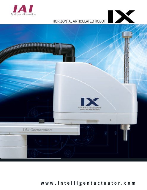
HORIZONTAL ARTICULATED ROBOT<br />
www.intelligentactuator.com
1<br />
IX <strong>SCARA</strong> Series<br />
[<strong>SCARA</strong> Series]<br />
V I S U A L I N D E X<br />
Standard Type<br />
The standard type<br />
combines the best<br />
performance and userfriendliness<br />
in its class.<br />
The selectable arm length<br />
(250 mm to 800 mm)<br />
provides the flexibility to<br />
accommodate a wide<br />
range of applications.<br />
NNN<br />
IX-NNN2515<br />
IX-NNN3515<br />
IX-NNN5020 (5030)<br />
IX-NNN6020 (6030)<br />
IX-NNN7020 (7040)<br />
IX-NNN8020 (8040)<br />
P11<br />
P11<br />
P12<br />
P13<br />
P14<br />
P15<br />
P16<br />
High-Speed Type<br />
The high-speed type offers<br />
enhanced performance in<br />
high-speed operation by<br />
combining a high-output<br />
motor with the standard<br />
body. It helps reduce cycle<br />
times.<br />
NSN<br />
IX-NSN5016<br />
IX-NSN6016<br />
P17<br />
P17<br />
P18<br />
Dustproof/<br />
Splash-proof Type<br />
The dustproof/splash-proof<br />
type adopts a protective<br />
structure conforming to<br />
IP65. This robot can be<br />
used in environments<br />
subject to powder dust or<br />
water splashes.<br />
NNW<br />
IX-NNW2515<br />
IX-NNW3515<br />
IX-NNW5020 (5030)<br />
IX-NNW6020 (6030)<br />
IX-NNW7020(7040)<br />
IX-NNW8020(8040)<br />
P19<br />
P19<br />
P20<br />
P21<br />
P22<br />
P23<br />
P24<br />
Wall-Mount Type<br />
This robot is mounted on a<br />
wall for operation. The<br />
space below the robot can<br />
be utilized effectively, so<br />
you will have more<br />
freedom in designing your<br />
equipment.<br />
TNN<br />
IX-TNN3015<br />
IX-TNN3515<br />
P25<br />
P25<br />
P26
2<br />
IX <strong>SCARA</strong> Series<br />
Wall-Mount<br />
Inverse Type<br />
This robot is the same as<br />
the wall-mounting type<br />
(TNN), but it is installed<br />
upside down. UNN is ideal<br />
for applications where the<br />
robot must handle loads<br />
located above it.<br />
UNN<br />
IX-UNN3015<br />
IX-UNN3515<br />
P25<br />
P25<br />
P26<br />
Ceiling Mount Type<br />
This robot is mounted on a<br />
ceiling for operation. The<br />
space below the robot can<br />
be utilized effectively, so<br />
you will have more<br />
freedom in designing your<br />
equipment.<br />
HNN<br />
IX-HNN5020<br />
IX-HNN6020<br />
IX-HNN7020(7040)<br />
IX-HNN8020(8040)<br />
P27<br />
P27<br />
P28<br />
P29<br />
P30<br />
Ceiling Mount Inverse Type<br />
(Tabletop Mount)<br />
This robot is the same as<br />
the ceiling mount type<br />
(HNN), but it is installed<br />
upside down. INN is ideal<br />
for applications where the<br />
robot must handle loads<br />
located above it.<br />
INN<br />
IX-INN5020<br />
IX-INN6020<br />
IX-INN7020(7040)<br />
IX-INN8020(8040)<br />
P27<br />
P27<br />
P28<br />
P29<br />
P30<br />
Clean Room Type<br />
This robot generates<br />
minimal particles and is<br />
ideal for operation in a<br />
clean room environment.<br />
The air inside the robot<br />
can be vacuumed if<br />
conformance to<br />
cleanliness class 10 is<br />
required.<br />
NNC<br />
IX-NNC2515<br />
IX-NNC3515<br />
IX-NNC5020 (5030)<br />
IX-NNC6020 (6030)<br />
IX-NNC7020 (7040)<br />
IX-NNC8020 (8040)<br />
P31<br />
P31<br />
P32<br />
P33<br />
P34<br />
P35<br />
P36
IX <strong>SCARA</strong> Series<br />
New Horizontal Articulated Robot IX Series Achieves Class<br />
Top Performance and High Cost Performance<br />
The IX Series achieved the best-in-class specification in every aspect—from<br />
high-speed performance and load capacity to positioning repeatability—<br />
after reviewing and redesigning all the components of the<br />
conventional IH Series robots. The IX Series also outdistances<br />
its rivals in user-friendliness, lineup and cost performance.<br />
3<br />
High-Performance<br />
1.<br />
Highest Speed, Load Capacity<br />
and Accuracy in Its Class<br />
Standard cycle time: 0.44 sec (*1)<br />
Positioning repeatability: ±0.01 mm/±0.005˚ (*2)<br />
Maximum load capacity: 20 kg (*3)<br />
*1 The standard cycle time refers to the time required to cycle back and<br />
forth over a vertical distance of 25 mm and horizontal distance of 300 mm<br />
(rough positioning).<br />
*2 If the arm length is 700/800, the repeatability<br />
becomes ±0.015 mm/±0.005˚.<br />
*3 Based on an arm length of 700/800.<br />
2.<br />
Command<br />
PATH<br />
Compact and Rigid<br />
The IX Series is significantly<br />
smaller compared with the<br />
conventional IH Series robots.<br />
The IX Series achieved<br />
enhanced rigidity in a<br />
lightweight body by comprising<br />
arm 1 using aluminum<br />
extruded material. This helped<br />
reduce the inertial load.<br />
3.<br />
300mm (12 in.)<br />
25mm<br />
(1 in.)<br />
Markedly Improved Tracing Accuracy<br />
and Interpolation Function<br />
The IX Series offers a markedly<br />
improved tracing accuracy as a<br />
result of higher controller<br />
processing speed and rigid robot<br />
construction.<br />
The robot can also perform threedimensional<br />
arc/pass motions to<br />
allow for easy, accurate<br />
dispensing operation.<br />
Operand 1<br />
P1<br />
Operand 2<br />
P20<br />
IH Series<br />
IX Series<br />
P1 start position<br />
P20 end position<br />
Path movement that consists of<br />
many points can be implemented<br />
with a single program line.<br />
Easy<br />
4.<br />
Greater Ease of Use<br />
An easy-to-use D-sub/25-pin connector is provided on<br />
top of the robot for user wiring. The user can also<br />
connect two ø4 tubes and two ø6 tubes to meet<br />
various tubing needs.<br />
The brake-release switch on the robot lets you release<br />
the brake even when the controller power is off (*1).<br />
The alarm indicator alerts you on each error generated<br />
in the robot (*2).<br />
Alarm indicator<br />
5.<br />
ø4 air filtering<br />
ø6 air filtering<br />
ø4 air filtering<br />
User connector<br />
Brake-release switch<br />
Spacer<br />
Easy Programming<br />
*1 24 VDC power must be<br />
supplied regardless of<br />
whether or not the brakerelease<br />
switch is used.<br />
*2 The alarm indicator must<br />
be wired by the user.<br />
The IX Series adopts Super SEL Language, a wellknown<br />
command language used by IAI Cartesian robots.<br />
With Super SEL, complex operations can be<br />
programmed easily. You can create desired programs<br />
right away without much knowledge of robot language.
4<br />
IX <strong>SCARA</strong> Series<br />
Plus<br />
6.<br />
Z-Axis<br />
Push Motion Function<br />
The Z-axis (vertical axis) can be<br />
pressed against the load, so<br />
you can use the robot to pressfit<br />
loads or control push force.<br />
7.<br />
Simple Interference<br />
Check Zone Function<br />
A maximum of 10 interference check<br />
zones can be set inside the robotís<br />
work envelope. When the load enters<br />
a check zone, the robot will inform<br />
you with a signal output. Use this<br />
function to conduct test operation at<br />
low speed.<br />
* The load must remain inside a zone for at<br />
least 5 msec to ensure accurate detection.<br />
8.<br />
Complete Absolute Operation<br />
All models adopt a 17-bit serial absolute encoder,<br />
so accurate positioning can be performed without<br />
homingeach time.<br />
If a need arises, an absolute reset can be<br />
performed easily and accurately using a<br />
dedicated jig (refer to “Robot Options” on P. 8).<br />
Variation<br />
9.<br />
Widest Variations<br />
in the Industry<br />
The IX Series provides the following<br />
six variations to choose from:<br />
• Standard type<br />
• High-speed type<br />
• Clean room type<br />
• Dustproof/splash-proof type<br />
• Wall mount/inverse type<br />
• Ceiling mount/inverse type<br />
Select one that best suits your intended<br />
application.
IX <strong>SCARA</strong> Series<br />
Specifications<br />
5<br />
Type<br />
Standard<br />
type<br />
NNN<br />
Highspeed<br />
type<br />
NSN<br />
Dustproof/<br />
splashproof<br />
type<br />
NNW<br />
Wallmount<br />
type<br />
TNN<br />
Wallmount<br />
inverse<br />
type UNN<br />
Ceilingmount<br />
type<br />
HNN<br />
Ceilingmount<br />
inverse<br />
type<br />
INN<br />
Clean<br />
room<br />
type<br />
NNC<br />
Arm length (mm), maximum composite speed (mm/s) Standard Load capacity (*1) Vertical axis stroke Model<br />
cycle<br />
250 350 500 600 700 800 time Rated Maximum Standard Optional<br />
mm mm mm mm mm mm (sec) (kg) (kg) (mm)<br />
3142<br />
mm/s<br />
0.46 1 3 150 - IX-NNN2515<br />
3142<br />
mm/s<br />
3142<br />
mm/s<br />
3560<br />
mm/s<br />
3979<br />
mm/s<br />
3979<br />
mm/s<br />
3979<br />
mm/s<br />
3560<br />
mm/s<br />
3979<br />
mm/s<br />
3979<br />
mm/s<br />
6283<br />
mm/s<br />
4712<br />
mm/s<br />
6283<br />
mm/s<br />
6283<br />
mm/s<br />
6283<br />
mm/s<br />
6283<br />
mm/s<br />
7121<br />
mm/s<br />
5236<br />
mm/s<br />
7121<br />
mm/s<br />
7121<br />
mm/s<br />
7121<br />
mm/s<br />
7121<br />
mm/s<br />
6597<br />
mm/s<br />
6597<br />
mm/s<br />
6597<br />
mm/s<br />
6597<br />
mm/s<br />
6597<br />
mm/s<br />
7121<br />
mm/s<br />
0.53<br />
0.44<br />
0.52<br />
0.50<br />
7121<br />
mm/s 0.52<br />
0.29<br />
to 0.30<br />
0.38<br />
to 0.39<br />
7121<br />
mm/s<br />
7121<br />
mm/s<br />
7121<br />
mm/s<br />
0.51<br />
0.59<br />
0.49<br />
0.55<br />
0.52<br />
0.52<br />
0.49<br />
0.53<br />
0.49<br />
0.53<br />
0.44<br />
0.52<br />
0.50<br />
0.52<br />
0.44<br />
0.52<br />
0.50<br />
0.52<br />
0.49<br />
0.58<br />
0.47<br />
0.54<br />
0.52<br />
0.52<br />
1<br />
2<br />
2<br />
5<br />
5<br />
1<br />
1<br />
1<br />
1<br />
2<br />
2<br />
5<br />
5<br />
1<br />
1<br />
1<br />
1<br />
2<br />
2<br />
5<br />
5<br />
2<br />
2<br />
5<br />
5<br />
1<br />
1<br />
2<br />
2<br />
5<br />
5<br />
3<br />
10<br />
10<br />
20<br />
20<br />
3<br />
3<br />
3<br />
3<br />
10<br />
10<br />
20<br />
20<br />
3<br />
3<br />
3<br />
3<br />
10<br />
10<br />
20<br />
20<br />
10<br />
10<br />
20<br />
20<br />
3<br />
3<br />
10<br />
10<br />
20<br />
20<br />
150<br />
200<br />
200<br />
200<br />
200<br />
160<br />
160<br />
150<br />
150<br />
200<br />
200<br />
200<br />
200<br />
150<br />
150<br />
150<br />
150<br />
200<br />
200<br />
200<br />
200<br />
200<br />
200<br />
200<br />
200<br />
150<br />
150<br />
200<br />
200<br />
200<br />
200<br />
-<br />
300<br />
300<br />
400<br />
400<br />
-<br />
-<br />
-<br />
-<br />
300<br />
300<br />
400<br />
400<br />
-<br />
-<br />
-<br />
-<br />
-<br />
-<br />
400<br />
400<br />
-<br />
-<br />
400<br />
400<br />
-<br />
-<br />
300<br />
300<br />
400<br />
400<br />
IX-NNN3515<br />
IX-NNN5020(5030)<br />
IX-NNN6020(6030)<br />
IX-NNN7020(7040)<br />
IX-NNN8020(8040)<br />
IX-NSN5016<br />
IX-NSN6016<br />
IX-NNW2515<br />
IX-NNW3515<br />
IX-NNW5020(5030)<br />
IX-NNW6020(6030)<br />
IX-NNW7020(7040)<br />
IX-NNW8020(8040)<br />
IX-TNN3015<br />
IX-TNN3515<br />
IX-UNN3015<br />
IX-UNN3515<br />
IX-HNN5020<br />
IX-HNN6020<br />
IX-HNN7020(7040)<br />
IX-HNN8020(8040)<br />
IX-INN5020<br />
IX-INN6020<br />
IX-INN7020(7040)<br />
IX-INN8020(8040)<br />
IX-NNC2515<br />
IX-NNC3515<br />
IX-NNC5020(5030)<br />
IX-NNC6020(6030)<br />
IX-NNC7020(7040)<br />
IX-NNC8020(8040)<br />
Page<br />
P11<br />
P12<br />
P13<br />
P14<br />
P15<br />
P16<br />
P17<br />
P18<br />
P19<br />
P20<br />
P21<br />
P22<br />
P23<br />
P24<br />
P25<br />
P26<br />
P25<br />
P26<br />
P27<br />
P28<br />
P29<br />
P30<br />
P27<br />
P28<br />
P29<br />
P30<br />
P31<br />
P32<br />
P33<br />
P34<br />
P35<br />
P36<br />
(*1) The rated load capacity indicates the maximum load that can be carried at the maximum operating speed. The maximum load capacity indicates the maximum load that can be carried at a reduced acceleration rate.
IX <strong>SCARA</strong> Series<br />
IX Series<br />
Points to Note<br />
<br />
(Note 1)<br />
Positioning repeatability<br />
“Positioning repeatability” refers to the positioning accuracy of repeated movements to a prestored<br />
position. This is not the same as “absolute positioning accuracy.”<br />
The specified positioning repeatability is measured in an ambient temperature of 20˚C constant.<br />
(Note 2)<br />
Maximum operating speed<br />
The specified maximum operating speed represents the speed of PTP command operation.<br />
High-speed movement will be limited in CP command operation (interpolation operation).<br />
(Note 3)<br />
Standard cycle time<br />
“Standard cycle time” refers to the time required to cycle back and forth over a vertical<br />
distance of 25 mm and horizontal distance of 300 mm (rough positioning).<br />
300mm<br />
<br />
The specified cycle time is based on a 2-kg load (5-kg load if the arm<br />
length is 700/800) and the maximum operating speed.<br />
25mm<br />
The robot cannot operate continuously at the maximum speed.<br />
(Note 4)<br />
Axis 3 push force<br />
“Axis 3 push force” represents the push force applied by the tip of the vertical axis. The value<br />
under “Push action” indicates the maximum push force to be applied when a programmed<br />
push command is executed. The value under “Maximum thrust” indicates the maximum thrust<br />
in a normal positioning operation. When a push action is performed during a normal<br />
positioning operation, a force corresponding to three times the maximum thrust may apply<br />
momentarily. When performing a push action, be sure to use a programmed push command.<br />
(Note 5)<br />
Axis 4 allowable<br />
inertial moment<br />
(Note 6)<br />
Alarm indicator<br />
“Axis 4 allowable inertial moment” indicates the allowable inertial moment of axis 4 (rotating<br />
axis) of the <strong>SCARA</strong> robot as calculated at the center of rotation.<br />
The offset from the center of rotation of axis 4 to the tool gravity center must be within 40 mm.<br />
If the tool gravity center is further away from the center of axis 4, the speed and/or<br />
acceleration rate must be reduced as necessary.<br />
The alarm indicator is located on top of arm 2 of the <strong>SCARA</strong> robot.<br />
The alarm indicator can be wired in such a way that it will illuminate in a certain condition<br />
such as when the controller generates an error. To use the alarm indicator, the user must<br />
provide a circuit that responds to the controllerís I/O output signal to supply 24 VDC to the<br />
applicable LED terminal in the user wiring.<br />
(Note 7)<br />
Brake-release switch<br />
The brake-release switch is also located on top of the robotís arm 2 near the alarm<br />
indicator.<br />
To release the brake, 24 VDC power must be supplied regardless of whether or not the<br />
brake-release switch is used. (Supply 24 VDC from a dedicated power supply separate from<br />
the 24 VDC power used for driving the I/Os.)<br />
(Note 8)<br />
Cable length<br />
(Note 9)<br />
Protection grade<br />
(protective structure)<br />
(Note 10)<br />
Air purge pressure<br />
(Note 11)<br />
Internal vacuuming<br />
The motor and encoder cables of the <strong>SCARA</strong> robot are directly connected to the robot.<br />
The IX Series doesnít use a cable joint, so changing the cable length on the delivered robot<br />
will be difficult.<br />
Select either 5 m (code 5L) or 10 m (10L) as the desired cable length when ordering.<br />
This grade indicates the level of actuator protection against water and solid foreign matters.<br />
The actuator is protected against solid foreign matters to a degree where dust will not enter the actuator.<br />
IP65 The actuator is protected against water intrusion to a degree where the actuator will not be negatively<br />
affected by water injected at a given angle.<br />
To use the dustproof/splash-proof type in an IP65 environment, air must be supplied from the<br />
air inlet located at side (or back) of the robot base (to perform air purge). The air purge pressure<br />
must conform to the common specification applicable to all robot types. (Supplied air must be<br />
clean, dry air of atmospheric pressure with a dew-point temperature of –20˚C or below.)<br />
To use the clean type in an environment of cleanliness class 10, the air inside the robot<br />
must be vacuumed from the air suction outlet located at side (or back) of the robot base.<br />
The suction rate must conform to the common specification applicable to all robot types.<br />
6
IX <strong>SCARA</strong> Series<br />
IX Series<br />
System Configuration Drawing<br />
Teaching pendant<br />
Model IA-T-X/XD/XA<br />
(Refer to P. 43.)<br />
(Provided by the user)<br />
Motor cable 5m (standard)<br />
(Emergency stop switch)<br />
Encoder cable 5m (standard)<br />
4m<br />
Controller<br />
Brake power cable<br />
(5m)<br />
(Y termination<br />
at end)<br />
Air tube<br />
(0.15m) (4 tubes)<br />
PC connection cable (5m)<br />
Model CB-ST-E1MW050-EB<br />
(Supplied with PC software)<br />
(Refer to P. 43.)<br />
PC software (optional)<br />
Model IA-101-X-MW<br />
(Refer to P. 43.)<br />
User cable (5m)<br />
(Y termination at end)<br />
24VDC<br />
power supply<br />
PIO flat cable (2m)<br />
Model CB-X-PIO020<br />
(See below.)<br />
PLC<br />
Each field network<br />
•DeviceNet (*1)<br />
•CC-Link (*2)<br />
•ProfiBus (*1)<br />
•Ethernet<br />
Serial communication unit<br />
•RS232C<br />
•RS422<br />
•RS485<br />
Power-supply voltage:<br />
single-phase 200VAC<br />
(Note 1) A teaching pendant older than Ver. 1.08<br />
cannot be used.<br />
(Note 2) PC software older than Ver. 2.0.0.0<br />
cannot be used.<br />
(*1) DeviceNet is a registered trademark of ODVA.<br />
(*2) CC-Link is a registered trademark of<br />
Mitsubishi Electric Corporation.<br />
(*3) ProfiBus is a registered trademark of Siemens AG.<br />
(Provided by the user)<br />
Robot Accessories<br />
• Caution labels<br />
• Positioning seals<br />
• Eyebolts<br />
• Service connectors<br />
Robot Options<br />
Controller Accessory<br />
• PIO flat cable<br />
Model CB-X-PIO<br />
Enter the desired cable length (L) of up to 10 m in ooo. Example) 080 = 8m<br />
No. Color<br />
Brown 1<br />
Wire No. Color<br />
Gray 2<br />
Wire No.<br />
Red 1<br />
White 2<br />
Orange 1<br />
Black 2<br />
Yellow 1<br />
Brown 3<br />
Green 1<br />
Red 3<br />
Blue 1<br />
Orange 3<br />
Purple 1<br />
Yellow 3<br />
Gray 1<br />
Green 3<br />
White 1<br />
Black 1<br />
Flat<br />
cable<br />
Blue 3<br />
Purple 3<br />
Flat<br />
cable<br />
Brown 2<br />
Gray 3<br />
Red 2<br />
White 3<br />
Orange 2<br />
Black 3<br />
Yellow 2<br />
Brown 4<br />
Green 2<br />
Red 4<br />
Blue 2<br />
Orange 4<br />
Purple 2<br />
Yellow 4<br />
Flat cable<br />
(50 conductors)<br />
Color<br />
Green 4<br />
Blue 4<br />
Purple 4<br />
Gray 4<br />
White 4<br />
Black 4<br />
Brown 5<br />
Red 5<br />
Orange 5<br />
Yellow 5<br />
Green 5<br />
Blue 5<br />
Purple 5<br />
Gray 5<br />
White 5<br />
Black 5<br />
No<br />
connector<br />
Wire<br />
Flat<br />
cable<br />
Name Model Description Page<br />
Absolute Data Storage Battery<br />
Absolute Reset Adjustment Jig<br />
Flange<br />
AB-3<br />
JG-1~3<br />
IX-FL-1~3<br />
Battery for storing the encoder’s absolute data<br />
Jig needed to execute an absolute reset<br />
Flange used to install to the tip of the Z-axis<br />
P8<br />
Controller Options<br />
7<br />
Name Model Description Page<br />
Teaching Pendant<br />
Teaching Pendant (With Deadman Switch)<br />
Teaching Pendant (ANSI)<br />
PC Software (DOS/V)<br />
PC Software (PC98)<br />
IA-T-X<br />
IA-T-XD<br />
IA-T-XA<br />
IA-101-X-MW<br />
IA-101-X-CW<br />
Allows for input and editing of position data, programs, parameters, etc., as well as manual operations.<br />
IA-T-X equipped with a deadman switch<br />
CE/ANSI-compliant type<br />
Allows for input and editing of position data, programs, parameters, etc.,<br />
as well as manual operations.<br />
P43
8<br />
IX <strong>SCARA</strong> Series<br />
Robot Options<br />
Absolute Data Backup Battery<br />
This battery is used to store the encoderís absolute data.<br />
(Install the battery inside the rear cover of the <strong>SCARA</strong> robot.)<br />
Model<br />
AB-3<br />
Remarks<br />
Common to all models<br />
AB-3<br />
Absolute Reset Adjustment Jig<br />
An appropriate adjustment jig is used to execute an absolute<br />
reset when the encoderís absolute data was lost.<br />
Model<br />
Remarks<br />
JG-1<br />
Arm length 500/600<br />
JG-2<br />
JG-3<br />
Arm length 250/350<br />
Arm length 700/800<br />
JG-1<br />
JG-2<br />
JG-3<br />
Flange<br />
Use an appropriate flange when mounting to the tip of the<br />
Z-axis arm.<br />
ø35<br />
ø16<br />
ø44<br />
ø20<br />
ø44<br />
ø25<br />
Model<br />
IX-FL-1<br />
IX-FL-2<br />
Remarks<br />
Arm length 500/600<br />
Arm length 250/350<br />
2 30<br />
6<br />
ø25h7<br />
ø60<br />
M5<br />
2<br />
47<br />
8<br />
ø34h7<br />
ø70<br />
2 47<br />
8<br />
ø34h7<br />
ø70<br />
IX-FL-3<br />
Arm length 700/800<br />
4-ø5.5<br />
45˚<br />
45˚<br />
45˚<br />
4-ø5.5<br />
4-ø5.5<br />
ø50<br />
ø5H7<br />
ø60<br />
ø5H7<br />
ø60<br />
+0.012 ø5H7( 0 )<br />
+ 25 – 0.012<br />
IX-FL-2 IX-FL-1 IX-FL-3
IX <strong>SCARA</strong> Series<br />
Unit Series Explanation of <strong>SCARA</strong> Robot Model Items<br />
Refer to the opposite page for details on each model item ( 1 through 8 ). The selection range for each item will<br />
vary depending on the robot type. For details, refer to the page corresponding to each model type.<br />
1 2 3 4 5 6 7 8<br />
Series Model Cable length<br />
Controller Standard Expansion I/O flat cable Power-supply<br />
type PIO I/O length voltage<br />
1<br />
<strong>SCARA</strong> robot,<br />
standard type<br />
NNN2515<br />
NNN3515<br />
NNN5020<br />
NNN5030<br />
NNN6020<br />
NNN6030<br />
NNN7020<br />
NNN7040<br />
NNN8020<br />
NNN8040<br />
2<br />
<strong>SCARA</strong> robot,<br />
high-speed type<br />
NSN5016<br />
NSN6016<br />
3<br />
4<br />
<strong>SCARA</strong> robot,<br />
dustproof/<br />
splash-proof type<br />
<strong>SCARA</strong> robot,<br />
wall-mount type<br />
(inverse type)<br />
IX<br />
NNW2515<br />
NNW3515<br />
NNW5020<br />
NNW5030<br />
NNW6020<br />
NNW6030<br />
NNW7020<br />
NNW7040<br />
NNW8020<br />
NNW8040<br />
TNN3015<br />
(UNN3015)<br />
TNN3515<br />
(UNN3515)<br />
5L<br />
10L<br />
KX<br />
JX<br />
N1<br />
N3<br />
P1<br />
P3<br />
DV<br />
CC<br />
PR<br />
ET<br />
EEE,<br />
etc.<br />
2<br />
3<br />
5<br />
0<br />
2<br />
5<br />
<strong>SCARA</strong> robot,<br />
ceiling-mount type<br />
(inverse type)<br />
HNN5020<br />
(INN5020)<br />
HNN6020<br />
(INN6020)<br />
HNN7020<br />
(INN7020)<br />
HNN7040<br />
(INN7040)<br />
HNN8020<br />
(INN8020)<br />
HNN8040<br />
(INN8040)<br />
9<br />
6<br />
<strong>SCARA</strong> robot,<br />
clean room type<br />
NNC2515<br />
NNC3515<br />
NNC5020<br />
NNC5030<br />
NNC6020<br />
NNC6030<br />
NNC7020<br />
NNC7040<br />
NNC8020<br />
NNC8040
IX <strong>SCARA</strong> Series<br />
Unlike other models, the <strong>SCARA</strong> robot is ordered as a combination of robot and controller.<br />
Items 1 through 3 specify the <strong>SCARA</strong> robot.<br />
Items 4 through 8 specify the controller.<br />
1<br />
Indicate the name of each series.<br />
3<br />
Indicate the length of the cable connecting the robot and<br />
the controller.<br />
Select either 5L (5 m) or 10L (10 m).<br />
Unlike a single-axis robot, the IX Series doesnít adopt a joint cable.<br />
The cable comes out directly from the robot.<br />
5<br />
Indicate the specification of the controllerís standard I/O slot.<br />
* N3 and P3 are dedicated options for the JX controller and cannot be specified for the KX controller.<br />
N1 : [NPN standard PIO] An NPN PIO board with 32 input points and 16 output points is installed (standard).<br />
N3 : [NPN multipoint PIO] An NPN multipoint PIO board with 48 input points and 48 output points is installed (dedicated option for the JX controller).<br />
P1 : [PNP standard PIO] A PNP PIO board with 32 input points and 16 output points is installed.<br />
P3 : [PNP multipoint PIO] A PNP multipoint PIO board with 48 input points and 48 output points is installed (dedicated option for the JX controller).<br />
DV : [DeviceNet connection specification] A DeviceNet connection board with a maximum of 256 input points and 256 output points is installed.<br />
CC : [CC-Link connection specification] A CC-Link connection board with a maximum of 256 input points and 256 output points is installed.<br />
PR : [ProfiBus connection specification] A ProfiBus connection board with a maximum of 256 input points and 256 output points is installed.<br />
ET : [Ethernet connection specification] An Ethernet connection board offering data communication capability is installed.<br />
6<br />
Series<br />
Cable length<br />
Standard PIO specification<br />
Expansion I/O specification<br />
Indicate the specification of the controllerís expansion slot.<br />
An expansion board can be installed in slot 1, 2 or 3 of the KX controller, or in slot 1 of the JX controller.<br />
Use a three-digit code (EEE) to specify the slot type. In the case of the JX controller having only one expansion slot,<br />
specify the slot using the first digit and leave “E” in the remaining two digits (oEE).<br />
* C, N3, P3, SA, SB and SC are dedicated options for the KX controller and cannot be specified for the JX controller.<br />
Indicate the model type (standard, high-speed, dustproof/<br />
splash-proof, wall-mount or ceiling-mount), arm length and<br />
Z-axis length.<br />
NNN Standard type<br />
NSN High-speed type<br />
NNW Dustproof/splash-proof type<br />
TNN Wall-mount type<br />
Select a dedicated controller (KX or JX type) for the<br />
<strong>SCARA</strong> robot.<br />
* Only the KX type may be specified if the arm length is 500 or longer.<br />
E : [Unused] Expansion board is not used.<br />
C : [CC-Link connection specification] A CC-Link connection board with 16 input points and 16 output points is installed (dedicated option for the KX controller).<br />
N1 : [NPN expansion PIO] An NPN PIO board with 32 input points and 16 output points is installed.<br />
N2 : [NPN expansion PIO] An NPN PIO board with 16 input points and 32 output points is installed.<br />
N3 : [NPN multipoint PIO] An NPN multipoint PIO board with 48 input points and 48 output points is installed (dedicated option for the KX controller).<br />
P1 : [PNP expansion PIO] A PNP PIO board with 32 input points and 16 output points is installed.<br />
P2 : [PNP expansion PIO] A PNP PIO board with 16 input points and 32 output points is installed.<br />
P3 : [PNP expansion PIO] A PNP PIO board with 48 input points and 48 output points is installed (dedicated option for the KX controller).<br />
SA : [Expansion SIO type A] An RS232C communication board is installed (dedicated option for the KX controller).<br />
SB : [Expansion SIO type B] An RS422 communication board is installed (dedicated option for the KX controller).<br />
SC : [Expansion SIO type C] An RS485 communication board is installed (dedicated option for the KX controller).<br />
7 I/O flat cable length<br />
8 Power-supply voltage<br />
2<br />
4<br />
Model<br />
Controller type<br />
UNN Wall-mount type (inverse type)<br />
HNN Ceiling-mount type<br />
INN Ceiling-mount type (inverse type)<br />
Indicate the length of the cable used for transmitting<br />
signals between the controller and the PLC.<br />
One cable is supplied with one I/O board installed in the<br />
standard slot or each expansion slot.<br />
2: 2m<br />
3: 3m<br />
5: 5m<br />
0: None (Specify this number if you have installed a<br />
network board instead of a standard I/O board.)<br />
Indicate the main power-supply voltage for the controller.<br />
The power-supply voltage is fixed to single-phase 200 VAC<br />
for a <strong>SCARA</strong> controller.<br />
10
IX Small <strong>SCARA</strong> Robot<br />
IX-NNN2515<br />
Small <strong>SCARA</strong> Robot Standard Type: Arm Length 250mm,<br />
Type Standard type Arm length 250mm<br />
Model/Specifications<br />
Model<br />
Common Specifications<br />
Axis<br />
configuration<br />
Axis 1<br />
Arm 1<br />
Axis 2<br />
IX–NNN2515–5L–o–o–o–o–2<br />
Arm 2<br />
Axis 3 Vertical axis<br />
Axis 4 Rotating axis<br />
Arm<br />
length<br />
(mm)<br />
125<br />
125<br />
—<br />
—<br />
Vertical (Z) Axis 150mm<br />
Motor<br />
capacity<br />
(W)<br />
200<br />
100<br />
100<br />
50<br />
Load capacity 1kg rated/3kg maximum<br />
■ Model items Series Model Cable length Controller type Standard I/O Expansion I/O I/O cable length Power-supply voltage<br />
(Example) IX — NNN2515 — 5L — KX — N1 — EEE — 2 — 2<br />
* Refer to P. 10 for details on the model items. * The above model code represents a combination of robot and controller.<br />
Work<br />
envelope<br />
±120˚<br />
±130˚<br />
150mm<br />
±360˚<br />
Positioning<br />
repeatability<br />
(mm)<br />
(Note 1)<br />
±0.010<br />
±0.010<br />
±0.005<br />
Maximum<br />
operating<br />
speed<br />
(Note 2)<br />
3142mm/s<br />
(Composite speed)<br />
1106mm/s<br />
360˚/s<br />
Standard<br />
cycle time<br />
(sec)<br />
(Note 3)<br />
* In the above model code, specify the desired controller in o. For details, refer to “Explanation of <strong>SCARA</strong> Robot Model Items” (P. 10).<br />
Load<br />
capacity<br />
(kg)<br />
Rated Maximum<br />
Axis 3<br />
push force (N)<br />
Push<br />
action<br />
(Note 4)<br />
Maximum<br />
thrust<br />
(Note 4)<br />
Axis 4<br />
allowable load<br />
Allowable<br />
inertial moment<br />
(kg•m 2 ) (Note 5)<br />
Allowable<br />
torque<br />
(N•m)<br />
0.46 1 3 65.3 90.9 0.015 1.9<br />
Encode type<br />
Absolute<br />
User wiring<br />
15-conductor AWG26 D-sub/15-pin connector with shield (socket)<br />
User tubing<br />
Air tube (O.D. ø4, I.D. ø2.5) x 3 (Normal working pressure 0.8MPa)<br />
Alarm indicator (Note 6) Red, small LED indicator x 1 (24 VDC must be supplied.)<br />
Brake-release switch (Note 7) Brake-release switch to prevent the vertical axis from dropping (24 VDC must be supplied.)<br />
Ambient temperature/humidity Temperature: 0~40˚C, humidity: 20~85%RH or below (non-condensing)<br />
Robot weight<br />
Cable length (Note 8)<br />
17.1kg<br />
5L: 5m (standard), 10L: 10m (optional)<br />
Dimensions<br />
Reference surface<br />
92.5 2-ø8H10<br />
55 130 Arm 1 stopper<br />
Panel<br />
ø4 (red)<br />
quick joint<br />
Red LED (*2)<br />
ø4 (black)<br />
quick joint<br />
ø4 (white)<br />
quick joint<br />
Brake-release switch<br />
User connector<br />
12<br />
Arm 2 stopper<br />
(424.5)<br />
155<br />
185<br />
100<br />
140<br />
160<br />
4-ø9<br />
ø16 counterbore,<br />
depth 0.5<br />
120˚<br />
R250<br />
R125<br />
130˚<br />
130˚<br />
R105.7<br />
R125<br />
120˚<br />
User spacer O.D. ø7,<br />
height 10, M4, depth 5 (*1)<br />
30<br />
ø35<br />
8 10<br />
57<br />
Detail view of panel<br />
ø11(I.D.)<br />
0<br />
ø16h7 ( -0.018 )<br />
Detail view of tip<br />
15<br />
652.5<br />
54 ST150 55 21<br />
372.5<br />
4 (Mechanical end)<br />
4 (Mechanical end)<br />
8<br />
ø16<br />
249.5<br />
30<br />
Arm 1<br />
125 125<br />
Reference surface<br />
Tapped hole for<br />
installation of peripheral<br />
(4-M4, depth 12)<br />
Same on the other side<br />
Arm 2<br />
250 (164)<br />
206 74<br />
(694)<br />
T slot for installation<br />
of peripheral (M3, M4)<br />
60 15<br />
12<br />
73.1˚<br />
160<br />
Operation prohibited area<br />
120<br />
Work envelope<br />
73.1˚<br />
*1: The external force applied to each spacer must not exceed 30 N in the axial direction or 2 N•m in<br />
the rotating direction.<br />
*2: To use the LED, the user must provide a circuit that takes signals from the controller’s I/O output<br />
and supplies 24 VDC to the applicable LED terminal in the user connector.<br />
Cables/tubes<br />
• Motor/encoder cable 5m/10m • User cable 5m/10m<br />
• Brake power cable 5m/10m • Air tube (3 pcs) 0.15m<br />
Applicable Controller Specifications<br />
11<br />
Applicable controller<br />
Features<br />
Maximum I/O points Serial communication Power-supply<br />
(inputs/outputs) unit voltage<br />
General-purpose type offering<br />
XSEL-KX<br />
176/160 points Can be installed. P37<br />
excellent expandability<br />
AC200V<br />
XSEL-JX Compact, space-saving type 80/64 points Cannot be installed. P37<br />
Page<br />
Caution<br />
Refer to P. 6 for the explanations of (Note 1) to (Note 8).
IX Small <strong>SCARA</strong> Robot<br />
IX-NNN3515Small <strong>SCARA</strong> Robot Standard Type: Arm Length 350mm,<br />
Vertical (Z) Axis 150mm<br />
Type Standard type Arm length 350mm Load capacity 1kg rated/3kg maximum<br />
■ Model items<br />
(Example) IX — NNN3515 — 5L — KX — N1 — EEE — 2 — 2<br />
* Refer to P. 10 for details on the model items. * The above model code represents a combination of robot and controller.<br />
Model/Specifications<br />
Model<br />
Common Specifications<br />
Series Model Cable length Controller type Standard I/O Expansion I/O I/O cable length Power-supply voltage<br />
Axis<br />
configuration<br />
Axis 1<br />
Arm 1<br />
Axis 2<br />
IX–NNN3515–5L–o–o–o–o–2<br />
Arm 2<br />
Axis 3 Vertical axis<br />
Axis 4 Rotating axis<br />
Arm<br />
length<br />
(mm)<br />
225<br />
125<br />
—<br />
—<br />
Motor<br />
capacity<br />
(W)<br />
200<br />
100<br />
100<br />
50<br />
Work<br />
envelope<br />
±120˚<br />
±135˚<br />
150mm<br />
±360˚<br />
Positioning<br />
repeatability<br />
(mm)<br />
(Note 1)<br />
±0.010<br />
±0.010<br />
±0.005<br />
Maximum<br />
operating<br />
speed<br />
(Note 2)<br />
3979mm/s<br />
(Composite speed)<br />
1106mm/s<br />
1600˚/s<br />
Standard<br />
cycle time<br />
(sec)<br />
(Note 3)<br />
* In the above model code, specify the desired controller in o. For details, refer to “Explanation of <strong>SCARA</strong> Robot Model Items” (P. 10).<br />
Load<br />
capacity<br />
(kg)<br />
Rated Maximum<br />
Axis 3<br />
push force (N)<br />
Push<br />
action<br />
(Note 4)<br />
Maximum<br />
thrust<br />
(Note 4)<br />
Axis 4<br />
allowable load<br />
Allowable<br />
inertial moment<br />
(kg•m 2 ) (Note 5)<br />
Allowable<br />
torque<br />
(N•m)<br />
0.53 1 3 65.3 90.9 0.015 1.9<br />
Encode type<br />
Absolute<br />
User wiring<br />
15-conductor AWG26 D-sub/15-pin connector with shield (socket)<br />
User tubing<br />
Air tube (O.D. ø4, I.D. ø2.5) x 3 (Normal working pressure 0.8MPa)<br />
Alarm indicator (Note 6) Red, small LED indicator x 1 (24 VDC must be supplied.)<br />
Brake-release switch (Note 7) Brake-release switch to prevent the vertical axis from dropping (24 VDC must be supplied.)<br />
Ambient temperature/humidity Temperature: 0~40˚C, humidity: 20~85%RH or below (non-condensing)<br />
Robot weight<br />
Cable length (Note 8)<br />
18.2kg<br />
5L: 5m (standard), 10L: 10m (optional)<br />
Dimensions<br />
Panel<br />
Reference surface<br />
92.5 2-ø8H10<br />
55 130<br />
Arm 1 stopper<br />
135˚<br />
135˚<br />
120˚<br />
120˚<br />
100<br />
140<br />
160<br />
ø4 (red)<br />
quick joint<br />
Red LED (*2)<br />
ø4 (black)<br />
quick joint<br />
User spacer O.D. ø7,<br />
height 10, M4, depth 5 (*1)<br />
30<br />
57<br />
Detail view of panel<br />
ø35<br />
8 10<br />
ø11(I.D.)<br />
0<br />
ø16h7 ( -0.018 )<br />
Detail view of tip<br />
ø4 (white)<br />
quick joint<br />
Brake-release switch<br />
User connector<br />
15<br />
12<br />
652.5<br />
54 ST150 55 21<br />
372.5<br />
4 (Mechanical end) 8 4 (Mechanical end)<br />
ø16<br />
Arm 2 stopper<br />
249.5<br />
30<br />
Arm 1<br />
(524.5)<br />
125 225<br />
Reference surface<br />
155<br />
185<br />
Tapped hole for installation of<br />
peripheral (4-M4, depth 12)<br />
Same on the other side<br />
Arm 2<br />
(164)<br />
4-ø9<br />
ø16 counterbore,<br />
depth 0.5<br />
250<br />
206 74<br />
(694)<br />
R350<br />
126.8˚<br />
T slot for installation<br />
of peripheral (M3, M4)<br />
60 15<br />
12<br />
R125<br />
160<br />
Operation prohibited area<br />
Work envelope<br />
120<br />
R125<br />
R162.7<br />
126.8˚<br />
*1: The external force applied to each spacer must not exceed 30 N in the axial direction or 2 N•m in<br />
the rotating direction.<br />
*2: To use the LED, the user must provide a circuit that takes signals from the controller’s I/O output<br />
and supplies 24 VDC to the applicable LED terminal in the user connector.<br />
Cables/tubes<br />
• Motor/encoder cable 5m/10m • User cable 5m/10m<br />
• Brake power cable 5m/10m • Air tube (3 pcs) 0.15m<br />
Applicable Controller Specifications<br />
Applicable controller<br />
Features<br />
Maximum I/O points Serial communication Power-supply<br />
(inputs/outputs) unit voltage<br />
General-purpose type offering<br />
XSEL-KX<br />
176/160 points Can be installed. P37<br />
excellent expandability<br />
AC200V<br />
XSEL-JX Compact, space-saving type 80/64 points Cannot be installed. P37<br />
Page<br />
Caution<br />
Refer to P. 6 for the explanations of (Note 1) to (Note 8).<br />
12
IX Medium <strong>SCARA</strong> Robot<br />
IX-NNN50<br />
Type Standard type Arm length 500mm Load capacity 2kg rated/10kg maximum<br />
■ Model items<br />
(Example) IX — NNN5020 — 5L — KX — N1 — EEE — 2 — 2<br />
* Refer to P. 10 for details on the model items. * The above model code represents a combination of robot and controller.<br />
Model/Specifications<br />
Model<br />
IX–NNN5020–5L–KX–o–o–o–2<br />
[IX–NNN5030–5L–KX–o–o–o–2]<br />
Common Specifications<br />
Series Model Cable length Controller type Standard I/O Expansion I/O I/O cable length Power-supply voltage<br />
Axis<br />
configuration<br />
Axis 1<br />
Axis 2<br />
Arm 1<br />
Arm 2<br />
Axis 3 Vertical axis<br />
Axis 4 Rotating axis<br />
Arm<br />
length<br />
(mm)<br />
250<br />
250<br />
—<br />
—<br />
Motor<br />
capacity<br />
(W)<br />
400<br />
200<br />
200<br />
100<br />
IX Medium <strong>SCARA</strong> Robot Standard Type:<br />
Arm Length 500mm, Vertical (Z) Axis 200mm (300mm)<br />
Work<br />
envelope<br />
±120˚<br />
±145˚<br />
200mm<br />
[300mm]<br />
±360˚<br />
Positioning<br />
repeatability<br />
(mm)<br />
(Note 1)<br />
±0.010<br />
±0.010<br />
±0.005<br />
Maximum<br />
operating<br />
speed<br />
(Note 2)<br />
6283mm/s<br />
(Composite speed)<br />
1393mm/s<br />
1200˚/s<br />
Standard<br />
cycle time<br />
(sec)<br />
(Note 3)<br />
* In the above model code, specify the desired controller in o. For details, refer to “Explanation of <strong>SCARA</strong> Robot Model Items” (P. 10).<br />
Load<br />
capacity<br />
(kg)<br />
Rated Maximum<br />
Axis 3<br />
push force (N)<br />
Push<br />
action<br />
(Note 4)<br />
Maximum<br />
thrust<br />
(Note 4)<br />
Axis 4<br />
allowable load<br />
Allowable<br />
inertial moment<br />
(kg•m 2 ) (Note 5)<br />
Allowable<br />
torque<br />
(N•m)<br />
0.44 2 10 108 152 0.06 3.3<br />
Encode type<br />
User wiring<br />
User tubing<br />
Alarm indicator (Note 6)<br />
Absolute<br />
25-conductor AWG26 D-sub/25-pin connector with shield (socket)<br />
Air tube (O.D. ø6, I.D. ø4) x 2 (Normal working pressure 0.8MPa)<br />
Air tube (O.D. ø4, I.D. ø2.5) x 2 (Normal working pressure 0.8MPa)<br />
Red, small LED indicator x 1 (24 VDC must be supplied.)<br />
Brake-release switch (Note 7) Brake-release switch to prevent the vertical axis from dropping (24 VDC must be supplied.)<br />
Ambient temperature/humidity Temperature: 0~40˚C, humidity: 20~85%RH or below (non-condensing)<br />
Robot weight 29.5kg<br />
Cable length (Note 8) 5L: 5m (standard), 10L: 10m (optional)<br />
Dimensions<br />
(723.2)<br />
Arm 2<br />
stopper<br />
175<br />
75 100<br />
120˚<br />
145˚<br />
145˚<br />
120˚<br />
R500<br />
R 150.4<br />
(130)<br />
120<br />
5<br />
(90)<br />
150<br />
200<br />
Reference<br />
surface<br />
ø146<br />
ø112<br />
99<br />
198<br />
820 [920]<br />
150 [50] 200ST [300ST] 470 [570]<br />
5 (Mechanical end) 72 19 (182.4) 5 (Mechanical end)<br />
(73.2)<br />
25 50<br />
Panel<br />
*1: The prepared hole 3-M4, depth 8 passes through the side panel of the arm.<br />
A long mounting screw will contact the mechanical parts inside the arm, so exercise caution.<br />
*2: The external force applied to each spacer must not exceed 30 N in the axial direction or 2 N•m in<br />
the rotating direction.<br />
*3: To use the LED, the user must provide a circuit that takes signals from the controller’s I/O output<br />
and supplies 24 VDC to the applicable LED terminal in the user connector.<br />
R40<br />
3-M4, depth 8<br />
Same on the other side (*1)<br />
20<br />
250<br />
500<br />
374<br />
20<br />
5<br />
250<br />
Reference surface<br />
50 75<br />
125<br />
Arm 2 Arm 1/<br />
arm 2<br />
stopper<br />
74<br />
Arm 1<br />
4-ø11<br />
ø24 counterbore,<br />
depth 5<br />
(684.1) (81.5)<br />
(765.6)<br />
Cables/tubes<br />
• Motor/encoder cable 5m/10m<br />
• Brake power cable 5m/10m<br />
• User cable<br />
5m/10m<br />
• Air tube (3 pcs) 0.15m<br />
ø6<br />
air-tube<br />
quick joint<br />
ø4<br />
air-tube<br />
quick joint<br />
87.8˚<br />
D-sub/25-pin<br />
connector for user<br />
wiring, socket<br />
fixing jig M2.6<br />
Red LED (*3)<br />
Brake-release<br />
switch<br />
Spacer<br />
O.D. ø7,<br />
height 10,<br />
M4,<br />
depth 5 (*2)<br />
200<br />
Operation prohibited area<br />
Work envelope<br />
47<br />
10 10<br />
Red<br />
Black<br />
A<br />
63<br />
28<br />
30<br />
ø44<br />
Yellow<br />
White<br />
A<br />
R125<br />
(18.5)<br />
21<br />
21.5<br />
119<br />
28<br />
22.5<br />
7.5<br />
Detail view of panel<br />
Detail view of tip<br />
19<br />
A-A section<br />
ø14, hollow<br />
0<br />
ø20h7 ( -0.021)<br />
Applicable Controller Specifications<br />
13<br />
Applicable controller<br />
XSEL-KX<br />
Features<br />
General-purpose type offering<br />
excellent expandability<br />
Maximum I/O points Serial communication Power-supply<br />
Page<br />
(inputs/outputs) unit voltage<br />
176/160 points Can be installed. AC200V P37<br />
Caution<br />
Refer to P. 6 for the explanations of (Note 1) to (Note 8).
R250<br />
IX-NNN60<br />
IX Medium <strong>SCARA</strong> Robot Standard Type:<br />
Arm Length 600mm, Vertical (Z) Axis 200mm (300mm)<br />
Type Standard type Arm length 600mm Load capacity 2kg rated/10kg maximum<br />
IX Medium <strong>SCARA</strong> Robot<br />
■ Model items<br />
Model/Specifications<br />
Model<br />
IX–NNN6020–5L–KX–o–o–o–2<br />
[IX–NNN6030–5L–KX–o–o–o–2]<br />
Common Specifications<br />
Series Model Cable length Controller type Standard I/O Expansion I/O I/O cable length Power-supply voltage<br />
(Example) IX — NNN6020 — 5L — KX — N1 — EEE — 2 — 2<br />
* Refer to P. 10 for details on the model items. * The above model code represents a combination of robot and controller.<br />
Axis<br />
configuration<br />
Axis 1<br />
Axis 2<br />
Arm 1<br />
Arm 2<br />
Axis 3 Vertical axis<br />
Axis 4 Rotating axis<br />
Arm<br />
length<br />
(mm)<br />
350<br />
250<br />
—<br />
—<br />
Motor<br />
capacity<br />
(W)<br />
400<br />
200<br />
200<br />
100<br />
Work<br />
envelope<br />
±120˚<br />
±145˚<br />
200mm<br />
[300mm]<br />
±360˚<br />
Positioning<br />
repeatability<br />
(mm)<br />
(Note 1)<br />
±0.010<br />
±0.010<br />
±0.005<br />
Maximum<br />
operating<br />
speed<br />
(Note 2)<br />
7121mm/s<br />
(Composite speed)<br />
1393mm/s<br />
1200˚/s<br />
Standard<br />
cycle time<br />
(sec)<br />
(Note 3)<br />
* In the above model code, specify the desired controller in o. For details, refer to “Explanation of <strong>SCARA</strong> Robot Model Items” (P. 10).<br />
Load<br />
capacity<br />
(kg)<br />
Rated Maximum<br />
Axis 3<br />
push force (N)<br />
Push<br />
action<br />
(Note 4)<br />
Maximum<br />
thrust<br />
(Note 4)<br />
Axis 4<br />
allowable load<br />
Allowable<br />
inertial moment<br />
(kg•m 2 ) (Note 5)<br />
Allowable<br />
torque<br />
(N•m)<br />
0.52 2 10 108 152 0.06 3.3<br />
Encode type<br />
User wiring<br />
User tubing<br />
Alarm indicator (Note 6)<br />
Absolute<br />
25-conductor AWG26 D-sub/25-pin connector with shield (socket)<br />
Air tube (O.D. ø6, I.D. ø4) x 2 (Normal working pressure 0.8MPa)<br />
Air tube (O.D. ø4, I.D. ø2.5) x 2 (Normal working pressure 0.8MPa)<br />
Red, small LED indicator x 1 (24 VDC must be supplied.)<br />
Brake-release switch (Note 7) Brake-release switch to prevent the vertical axis from dropping (24 VDC must be supplied.)<br />
Ambient temperature/humidity Temperature: 0~40˚C, humidity: 20~85%RH or below (non-condensing)<br />
Robot weight 30.5kg<br />
Cable length (Note 8) 5L: 5m (standard), 10L: 10m (optional)<br />
Dimensions<br />
Arm 2<br />
stopper<br />
(823.2)<br />
175<br />
75 100<br />
145˚<br />
145˚<br />
120˚<br />
120˚<br />
(130)<br />
120<br />
(90)<br />
150<br />
200<br />
R600<br />
R 204<br />
5<br />
Reference<br />
surface<br />
ø146<br />
ø112<br />
99<br />
198<br />
820 [920]<br />
150 [50] 200ST [300ST] 470 [570]<br />
5 (Mechanical end) 72 19 (182.4) 5 (Mechanical end)<br />
(73.2)<br />
25 50<br />
250<br />
600<br />
Panel<br />
3-M4, depth 8<br />
Same on the other side (*1)<br />
20<br />
374<br />
350<br />
Reference surface<br />
R40<br />
Arm 1<br />
50 75<br />
125<br />
Arm 2 Arm 1/<br />
arm 2<br />
stopper<br />
20<br />
5<br />
*1: The prepared hole 3-M4, depth 8 passes through the side panel of the arm.<br />
A long mounting screw will contact the mechanical parts inside the arm, so exercise caution.<br />
*2: The external force applied to each spacer must not exceed 30 N in the axial direction or 2 N•m in<br />
the rotating direction.<br />
*3: To use the LED, the user must provide a circuit that takes signals from the controller’s I/O output<br />
and supplies 24 VDC to the applicable LED terminal in the user connector.<br />
74<br />
4-ø11<br />
ø24 counterbore,<br />
depth 5<br />
(684.1) (81.5)<br />
(765.6)<br />
Cables/tubes<br />
• Motor/encoder cable 5m/10m<br />
• Brake power cable 5m/10m<br />
• User cable<br />
5m/10m<br />
• Air tube (3 pcs) 0.15m<br />
114.3˚<br />
ø6<br />
air-tube<br />
quick joint<br />
ø4<br />
air-tube<br />
quick joint<br />
D-sub/25-pin<br />
connector for user<br />
wiring, socket<br />
fixing jig M2.6<br />
Red LED (*3)<br />
Brake-release<br />
switch<br />
Spacer<br />
O.D. ø7,<br />
height 10,<br />
M4,<br />
depth 5 (*2)<br />
Operation prohibited area<br />
Work envelope<br />
47<br />
10 10<br />
Red<br />
Black<br />
A<br />
200<br />
63<br />
28<br />
30<br />
ø44<br />
Yellow<br />
White<br />
A<br />
Detail view of tip<br />
(18.5)<br />
21<br />
21.5<br />
119<br />
28<br />
22.5<br />
7.5<br />
Detail view of panel<br />
19<br />
A-A section<br />
ø14, hollow<br />
0<br />
ø20h7 ( -0.021)<br />
Applicable Controller Specifications<br />
Applicable controller<br />
XSEL-KX<br />
Features<br />
General-purpose type offering<br />
excellent expandability<br />
Maximum I/O points Serial communication Power-supply<br />
Page<br />
(inputs/outputs) unit voltage<br />
176/160 points Can be installed. AC200V P37<br />
Caution<br />
Refer to P. 6 for the explanations of (Note 1) to (Note 8).<br />
14
R350<br />
IX Large <strong>SCARA</strong> Robot<br />
IX-NNN70<br />
■ Model items<br />
(Example) IX — NNN7020 — 5L — KX — N1 — EEE — 2 — 2<br />
Model/Specifications<br />
Common Specifications<br />
IX Large <strong>SCARA</strong> Robot Standard Type:<br />
Arm Length 700mm, Vertical (Z) Axis 200mm (400mm)<br />
Type Standard type Arm length 700mm Load capacity 5kg rated/20kg maximum<br />
Series Model Cable length Controller type Standard I/O Expansion I/O I/O cable length Power-supply voltage<br />
* Refer to P. 10 for details on the model items. * The above model code represents a combination of robot and controller.<br />
Model<br />
IX–NNN7020–5L–KX–o–o–o–2<br />
[IX–NNN7040–5L–KX–o–o–o–2]<br />
Axis<br />
configuration<br />
Axis 1<br />
Axis 2<br />
Arm 1<br />
Arm 2<br />
Axis 3 Vertical axis<br />
Axis 4 Rotating axis<br />
Arm<br />
length<br />
(mm)<br />
350<br />
350<br />
—<br />
—<br />
Motor<br />
capacity<br />
(W)<br />
750<br />
400<br />
400<br />
200<br />
Work<br />
envelope<br />
±125˚<br />
±145˚<br />
200mm<br />
[400mm]<br />
±360˚<br />
Positioning<br />
repeatability<br />
(mm)<br />
(Note 1)<br />
±0.015<br />
±0.010<br />
±0.005<br />
Maximum<br />
operating<br />
speed<br />
(Note 2)<br />
6597mm/s<br />
(Composite speed)<br />
1583mm/s<br />
1200˚/s<br />
Standard<br />
cycle time<br />
(sec)<br />
(Note 3)<br />
* In the above model code, specify the desired controller in o. For details, refer to “Explanation of <strong>SCARA</strong> Robot Model Items” (P. 10).<br />
Load<br />
capacity<br />
(kg)<br />
Rated Maximum<br />
Axis 3<br />
push force (N)<br />
Push<br />
action<br />
(Note 4)<br />
Maximum<br />
thrust<br />
(Note 4)<br />
Axis 4<br />
allowable load<br />
Allowable<br />
inertial moment<br />
(kg•m 2 ) (Note 5)<br />
Allowable<br />
torque<br />
(N•m)<br />
0.50 5 20 188 265 0.1 6.7<br />
Encode type<br />
User wiring<br />
User tubing<br />
Alarm indicator (Note 6)<br />
Absolute<br />
25-conductor AWG26 D-sub/25-pin connector with shield (socket)<br />
Air tube (O.D. ø6, I.D. ø4) x 2 (Normal working pressure 0.8MPa)<br />
Air tube (O.D. ø4, I.D. ø2.5) x 2 (Normal working pressure 0.8MPa)<br />
Red, small LED indicator x 1 (24 VDC must be supplied.)<br />
Brake-release switch (Note 7) Brake-release switch to prevent the vertical axis from dropping (24 VDC must be supplied.)<br />
Ambient temperature/humidity Temperature: 0~40˚C, humidity: 20~85%RH or below (non-condensing)<br />
Robot weight 58kg<br />
Cable length (Note 8) 5L: 5m (standard), 10L: 10m (optional)<br />
Dimensions<br />
(65)<br />
(971.5)<br />
350 350<br />
(206.5)<br />
Arm 2<br />
stopper<br />
125˚<br />
145˚<br />
145˚<br />
125˚<br />
7<br />
Reference<br />
surface<br />
(ø188)<br />
(ø144)<br />
131<br />
262<br />
(169)<br />
962 [1162]<br />
258 [58] 200ST [400ST] 504 [704]<br />
6 (Mechanical end) 73 (263.4)<br />
6 (Mechanical end)<br />
22.5<br />
(134.6)<br />
61 51<br />
*1: The prepared hole 3-M4, depth 8 passes through the side panel of the arm.<br />
*2: The external force applied to each spacer must not exceed 30 N in the axial direction or 2<br />
N•m in the rotating direction.<br />
*3: To use the LED, the user must provide a circuit that takes signals from the controller’s I/O<br />
output and supplies 24 VDC to the applicable LED terminal in the user connector.<br />
20<br />
25˚<br />
Panel<br />
3-M4, depth 8<br />
Same on the<br />
other side (*1)<br />
468<br />
(R55)<br />
60 95<br />
(34) 155 (34)<br />
223<br />
Arm 2<br />
7<br />
28<br />
Reference surface<br />
Arm 1/<br />
arm 2<br />
stopper<br />
Arm 1<br />
91<br />
(81.5)<br />
(90)<br />
200<br />
268<br />
4-14 drilled through<br />
ø30 counterbore,<br />
depth 5<br />
(853)<br />
(934)<br />
Cables/tubes<br />
• Motor/encoder cable 5m/10m<br />
• Brake power cable 5m/10m<br />
• User cable<br />
5m/10m<br />
• Air tube (4 pcs) 0.15m<br />
ø6<br />
air-tube<br />
quick joint<br />
ø4<br />
air-tube<br />
quick joint<br />
20<br />
R700<br />
D-sub/25-pin<br />
connector for user<br />
wiring, socket<br />
fixing jig M2.6<br />
Red LED (*3)<br />
Brake-release<br />
switch<br />
Spacer O.D. ø7,<br />
height 10, M4,<br />
depth 5 (*2)<br />
47<br />
82.5˚<br />
10 10<br />
Red<br />
Black<br />
63<br />
28<br />
Yellow<br />
White<br />
R210.5<br />
250<br />
Operation prohibited area<br />
Work envelope<br />
30<br />
Detail view of panel<br />
A<br />
ø18, hollow<br />
0<br />
ø25h7 ( -0.021)<br />
Detail view of tip<br />
A<br />
(18.5)<br />
21<br />
21.5<br />
28<br />
22.5<br />
7.5<br />
119<br />
A-A section<br />
23.5<br />
Applicable Controller Specifications<br />
15<br />
Applicable controller<br />
XSEL-KX<br />
Features<br />
General-purpose type offering<br />
excellent expandability<br />
Maximum I/O points Serial communication Power-supply<br />
Page<br />
(inputs/outputs) unit voltage<br />
176/160 points Can be installed. AC200V P37<br />
Caution<br />
Refer to P. 6 for the explanations of (Note 1) to (Note 8).
R350<br />
IX-NNN80<br />
IX Medium <strong>SCARA</strong> Robot Standard Type:<br />
Arm Length 800mm, Vertical (Z) Axis 200mm (400mm)<br />
Type Standard type Arm length 800mm Load capacity 5kg rated/20kg maximum<br />
IX Large <strong>SCARA</strong> Robot<br />
■ Model items<br />
(Example) IX — NNN8020 — 5L — KX — N1 — EEE — 2 — 2<br />
Model/Specifications<br />
Model<br />
IX–NNN8020–5L–KX–o–o–o–2<br />
[IX–NNN8040–5L–KX–o–o–o–2]<br />
Common Specifications<br />
Series Model Cable length Controller type Standard I/O Expansion I/O I/O cable length Power-supply voltage<br />
* Refer to P. 10 for details on the model items. * The above model code represents a combination of robot and controller.<br />
Axis<br />
configuration<br />
Axis 1<br />
Axis 2<br />
Arm 1<br />
Arm 2<br />
Axis 3 Vertical axis<br />
Axis 4 Rotating axis<br />
Arm<br />
length<br />
(mm)<br />
450<br />
350<br />
—<br />
—<br />
Motor<br />
capacity<br />
(W)<br />
750<br />
400<br />
400<br />
200<br />
Work<br />
envelope<br />
±125˚<br />
±145˚<br />
200mm<br />
[400mm]<br />
±360˚<br />
Positioning<br />
repeatability<br />
(mm)<br />
(Note 1)<br />
±0.015<br />
±0.010<br />
±0.005<br />
Maximum<br />
operating<br />
speed<br />
(Note 2)<br />
7121mm/s<br />
(Composite speed)<br />
1583mm/s<br />
1200˚/s<br />
Standard<br />
cycle time<br />
(sec)<br />
(Note 3)<br />
* In the above model code, specify the desired controller in o. For details, refer to “Explanation of <strong>SCARA</strong> Robot Model Items” (P. 10).<br />
Load<br />
capacity<br />
(kg)<br />
Rated Maximum<br />
Axis 3<br />
push force (N)<br />
Push<br />
action<br />
(Note 4)<br />
Maximum<br />
thrust<br />
(Note 4)<br />
Axis 4<br />
allowable load<br />
Allowable<br />
inertial moment<br />
(kg•m 2 ) (Note 5)<br />
Allowable<br />
torque<br />
(N•m)<br />
0.52 5 20 188 265 0.1 6.7<br />
Encode type<br />
User wiring<br />
User tubing<br />
Alarm indicator (Note 6)<br />
Absolute<br />
25-conductor AWG26 D-sub/25-pin connector with shield (socket)<br />
Air tube (O.D. ø6, I.D. ø4) x 2 (Normal working pressure 0.8MPa)<br />
Air tube (O.D. ø4, I.D. ø2.5) x 2 (Normal working pressure 0.8MPa)<br />
Red, small LED indicator x 1 (24 VDC must be supplied.)<br />
Brake-release switch (Note 7) Brake-release switch to prevent the vertical axis from dropping (24 VDC must be supplied.)<br />
Ambient temperature/humidity Temperature: 0~40˚C, humidity: 20~85%RH or below (non-condensing)<br />
Robot weight 60kg<br />
Cable length (Note 8) 5L: 5m (standard), 10L: 10m (optional)<br />
Dimensions<br />
(65)<br />
(1071.5)<br />
350 450<br />
(206.5)<br />
Arm 2<br />
stopper<br />
145˚<br />
145˚<br />
125˚<br />
125˚<br />
(169)<br />
7<br />
(90)<br />
200<br />
268<br />
Reference<br />
surface<br />
(ø188)<br />
(ø144)<br />
131<br />
262<br />
962 [1162]<br />
258 [58] 200ST [400ST] 504 [704]<br />
6 (Mechanical end) 73 (263.4)<br />
6 (Mechanical end)<br />
22.5<br />
(134.6)<br />
61 51<br />
Panel<br />
*1: The prepared hole 3-M4, depth 8 passes through the side panel of the arm.<br />
*2: The external force applied to each spacer must not exceed 30 N in the axial direction or 2<br />
N•m in the rotating direction.<br />
*3: To use the LED, the user must provide a circuit that takes signals from the controller’s I/O<br />
output and supplies 24 VDC to the applicable LED terminal in the user connector.<br />
20<br />
25˚<br />
3-M4, depth 8<br />
Same on the<br />
other side (*1)<br />
Arm 2<br />
468<br />
7<br />
28<br />
4-14 drilled through<br />
ø30 counterbore,<br />
60 95<br />
depth 5<br />
(34) 155 (34)<br />
223<br />
(R55)<br />
Reference surface<br />
Arm 1<br />
91<br />
Arm 1/<br />
arm 2<br />
stopper<br />
(853) (81)<br />
(934)<br />
Cables/tubes<br />
• Motor/encoder cable 5m/10m<br />
• Brake power cable 5m/10m<br />
• User cable<br />
5m/10m<br />
• Air tube (4 pcs) 0.15m<br />
ø6<br />
air-tube<br />
quick joint<br />
ø4<br />
air-tube<br />
quick joint<br />
R800<br />
99.1˚<br />
D-sub/25-pin<br />
connector for user<br />
wiring, socket<br />
fixing jig M2.6<br />
Red LED (*3)<br />
Brake-release<br />
switch<br />
Spacer O.D. ø7,<br />
height 10, M4,<br />
depth 5 (*2)<br />
20<br />
47<br />
10 10<br />
R258.8<br />
250<br />
Operation prohibited area<br />
Work envelope<br />
Red<br />
Black<br />
63<br />
28<br />
Yellow<br />
White<br />
30<br />
Detail view of panel<br />
A<br />
A<br />
ø18, hollow<br />
0<br />
ø25h7 ( -0.021)<br />
Detail view of tip<br />
(18.5)<br />
21<br />
21.5<br />
28<br />
22.5<br />
7.5<br />
119<br />
A-A section<br />
23.5<br />
Applicable Controller Specifications<br />
Applicable controller<br />
XSEL-KX<br />
Features<br />
General-purpose type offering<br />
excellent expandability<br />
Maximum I/O points Serial communication Power-supply<br />
Page<br />
(inputs/outputs) unit voltage<br />
176/160 points Can be installed. AC200V P37<br />
Caution<br />
Refer to P. 6 for the explanations of (Note 1) to (Note 8).<br />
16
IX Medium <strong>SCARA</strong> Robot<br />
IX-NSN5016<br />
IX<br />
■ Model items<br />
Model/Specifications<br />
Common Specifications<br />
Medium <strong>SCARA</strong> Robot High-speed Type:<br />
Arm Length 500mm, Vertical (Z) Axis 160mm<br />
Type High-speed type Arm length 500mm Load capacity 1kg rated/3kg maximum<br />
Series Model Cable length Controller type Standard I/O Expansion I/O I/O cable length Power-supply voltage<br />
(Example) IX — NSN5016 — 5L — KX — N1 — EEE — 2 — 2<br />
* Refer to P. 10 for details on the model items. * The above model code represents a combination of robot and controller.<br />
Model<br />
IX–NSN5016–5L–KX–o–o–o–2<br />
Axis<br />
configuration<br />
Axis 1<br />
Axis 2<br />
Arm 1<br />
Arm 2<br />
Axis 3 Vertical axis<br />
Axis 4 Rotating axis<br />
Arm<br />
length<br />
(mm)<br />
250<br />
250<br />
—<br />
—<br />
Motor<br />
capacity<br />
(W)<br />
750<br />
600<br />
200<br />
100<br />
Work<br />
envelope<br />
±120˚<br />
±145˚<br />
160mm<br />
±360˚<br />
Positioning<br />
repeatability<br />
(mm)<br />
(Note 1)<br />
±0.010<br />
±0.010<br />
±0.010<br />
Maximum<br />
operating<br />
speed<br />
(Note 2)<br />
4712mm/s<br />
(Composite speed)<br />
1085mm/s<br />
1800˚/s<br />
Standard<br />
cycle time<br />
(sec)<br />
(Note 3)<br />
* In the above model code, specify the desired controller in o. For details, refer to “Explanation of <strong>SCARA</strong> Robot Model Items” (P. 10).<br />
0.29<br />
to<br />
0.30<br />
Load<br />
capacity<br />
(kg)<br />
Rated Maximum<br />
Axis 3<br />
push force (N)<br />
Push<br />
action<br />
(Note 4)<br />
Maximum<br />
thrust<br />
(Note 4)<br />
Axis 4<br />
allowable load<br />
Allowable<br />
inertial moment<br />
(kg•m 2 ) (Note 5)<br />
Allowable<br />
torque<br />
(N•m)<br />
1 3 135 190 0.015 2.2<br />
Encode type<br />
User wiring<br />
User tubing<br />
Alarm indicator (Note 6)<br />
Absolute<br />
25-conductor AWG26 D-sub/25-pin connector with shield (socket)<br />
Air tube (O.D. ø6, I.D. ø4) x 2 (Normal working pressure 0.8MPa)<br />
Air tube (O.D. ø4, I.D. ø2.5) x 2 (Normal working pressure 0.8MPa)<br />
Red, small LED indicator x 1 (24 VDC must be supplied.)<br />
Brake-release switch (Note 7) Brake-release switch to prevent the vertical axis from dropping (24 VDC must be supplied.)<br />
Ambient temperature/humidity Temperature: 0~40˚C, humidity: 20~85%RH or below (non-condensing)<br />
Robot weight 32kg<br />
Cable length (Note 8) 5L: 5m (standard), 10L: 10m (optional)<br />
Dimensions<br />
(723.2)<br />
Arm 2<br />
stopper<br />
175<br />
75 100<br />
120˚<br />
R500<br />
145˚<br />
145˚<br />
R150.4<br />
120˚<br />
(130)<br />
120<br />
(90)<br />
150<br />
200<br />
5<br />
Reference<br />
surface<br />
ø146<br />
ø112<br />
99<br />
198<br />
5.5<br />
(Mechanical end)<br />
775<br />
160ST 448.5<br />
5 (Mechanical end) 95.5 19 (182.4)<br />
166.5<br />
(73.2)<br />
25 50<br />
*1: The prepared hole 3-M4, depth 8 passes through the side panel of the arm.<br />
A long mounting screw will contact the mechanical parts inside the arm, so exercise caution.<br />
*2: The external force applied to each spacer must not exceed 30 N in the axial direction or 2 N•m in<br />
the rotating direction.<br />
*3: To use the LED, the user must provide a circuit that takes signals from the controller’s I/O output<br />
and supplies 24 VDC to the applicable LED terminal in the user connector.<br />
25˚<br />
250<br />
Panel<br />
500<br />
374<br />
Reference surface<br />
Arm 2<br />
3-M4, depth 8<br />
Same on the other side (*1)<br />
20<br />
20<br />
5<br />
R40<br />
250<br />
50 75<br />
125<br />
Arm 1<br />
Arm 1/<br />
arm 2<br />
stopper<br />
74<br />
4-ø11<br />
ø24 counterbore,<br />
depth 5<br />
(684.1) (81.5)<br />
(800.1)<br />
Cables/tubes<br />
• Motor/encoder cable 5m/10m<br />
• Brake power cable 5m/10m<br />
• User cable<br />
5m/10m<br />
• Air tube (4 pcs) 0.15m<br />
87.8˚<br />
ø6<br />
air-tube<br />
quick joint<br />
ø4<br />
air-tube<br />
quick joint<br />
D-sub/25-pin<br />
connector for user<br />
wiring, socket<br />
fixing jig M2.6<br />
Red LED (*3)<br />
Brake-release<br />
switch<br />
Spacer<br />
O.D. ø7,<br />
height 10,<br />
M4,<br />
depth 5 (*2)<br />
200<br />
Operation prohibited area<br />
Work envelope<br />
74.5<br />
8 10<br />
Red<br />
Black<br />
A<br />
63<br />
28<br />
30<br />
Yellow<br />
White<br />
A<br />
R250<br />
(18.5)<br />
21<br />
21.5<br />
119<br />
28<br />
22.5<br />
7.5<br />
Detail view of panel<br />
ø35<br />
Detail view of tip<br />
15<br />
A-A section<br />
ø11, hollow<br />
0<br />
ø16h7 ( -0.018)<br />
Applicable Controller Specifications<br />
17<br />
Applicable controller<br />
XSEL-KX<br />
Features<br />
General-purpose type offering<br />
excellent expandability<br />
Maximum I/O points Serial communication Power-supply<br />
Page<br />
(inputs/outputs) unit voltage<br />
176/160 points Can be installed. AC200V P37<br />
Caution<br />
Refer to P. 6 for the explanations of (Note 1) to (Note 8).
IX-NSN6016<br />
IX Medium <strong>SCARA</strong> Robot High-speed Type:<br />
Arm Length 600mm, Vertical (Z) Axis 160mm<br />
Type High-speed type Arm length 600mm Load capacity 1kg rated/3kg maximum<br />
IX Medium <strong>SCARA</strong> Robot<br />
■ Model items<br />
(Example) IX — NSN6016 — 5L — KX — N1 — EEE — 2 — 2<br />
Model/Specifications<br />
Common Specifications<br />
Series Model Cable length Controller type Standard I/O Expansion I/O I/O cable length Power-supply voltage<br />
* Refer to P. 10 for details on the model items. * The above model code represents a combination of robot and controller.<br />
Model<br />
IX–NSN6016–5L–KX–o–o–o–2<br />
Axis<br />
configuration<br />
Axis 1<br />
Axis 2<br />
Arm 1<br />
Arm 2<br />
Axis 3 Vertical axis<br />
Axis 4 Rotating axis<br />
Arm<br />
length<br />
(mm)<br />
350<br />
250<br />
—<br />
—<br />
Motor<br />
capacity<br />
(W)<br />
750<br />
600<br />
200<br />
100<br />
Work<br />
envelope<br />
±120˚<br />
±145˚<br />
160mm<br />
±360˚<br />
Positioning<br />
repeatability<br />
(mm)<br />
(Note 1)<br />
±0.010<br />
±0.010<br />
±0.010<br />
Maximum<br />
operating<br />
speed<br />
(Note 2)<br />
5236mm/s<br />
(Composite speed)<br />
1085mm/s<br />
1800˚/s<br />
Standard<br />
cycle time<br />
(sec)<br />
(Note 3)<br />
* In the above model code, specify the desired controller in o. For details, refer to “Explanation of <strong>SCARA</strong> Robot Model Items” (P. 10).<br />
0.38<br />
to<br />
0.39<br />
Load<br />
capacity<br />
(kg)<br />
Rated Maximum<br />
Axis 3<br />
push force (N)<br />
Push<br />
action<br />
(Note 4)<br />
Maximum<br />
thrust<br />
(Note 4)<br />
Axis 4<br />
allowable load<br />
Allowable<br />
inertial moment<br />
(kg•m 2 ) (Note 5)<br />
Allowable<br />
torque<br />
(N•m)<br />
1 3 135 190 0.015 2.2<br />
Encode type<br />
User wiring<br />
User tubing<br />
Alarm indicator (Note 6)<br />
Absolute<br />
25-conductor AWG26 D-sub/25-pin connector with shield (socket)<br />
Air tube (O.D. ø6, I.D. ø4) x 2 (Normal working pressure 0.8MPa)<br />
Air tube (O.D. ø4, I.D. ø2.5) x 2 (Normal working pressure 0.8MPa)<br />
Red, small LED indicator x 1 (24 VDC must be supplied.)<br />
Brake-release switch (Note 7) Brake-release switch to prevent the vertical axis from dropping (24 VDC must be supplied.)<br />
Ambient temperature/humidity Temperature: 0~40˚C, humidity: 20~85%RH or below (non-condensing)<br />
Robot weight 33kg<br />
Cable length (Note 8) 5L: 5m (standard), 10L: 10m (optional)<br />
Dimensions<br />
Arm 2<br />
stopper<br />
(823.2)<br />
175<br />
75 100<br />
120˚<br />
145˚<br />
145˚<br />
120˚<br />
5.5<br />
(Mechanical end)<br />
ø146<br />
ø112<br />
25˚<br />
250<br />
600<br />
350<br />
5<br />
(130)<br />
120<br />
(90)<br />
150<br />
200<br />
R600<br />
R204<br />
Panel<br />
R40<br />
50 75<br />
125<br />
4-ø11<br />
ø24 counterbore,<br />
depth 5<br />
114.3˚<br />
200<br />
R250<br />
Operation prohibited area<br />
Work envelope<br />
775<br />
166.5 160ST 448.5<br />
5 (Mechanical end) 95.5 19 (182.4)<br />
(73.2)<br />
25 50<br />
Arm 2<br />
3-M4, depth 8<br />
Same on the other side (*1)<br />
20<br />
374<br />
Arm 1<br />
Arm 1/<br />
arm 2<br />
stopper<br />
(684.1) (116)<br />
(800.1)<br />
ø6<br />
air-tube<br />
63<br />
quick joint 28<br />
ø4<br />
air-tube<br />
quick joint<br />
Red Yellow<br />
D-sub/25-pin<br />
connector for user Black White<br />
wiring, socket<br />
fixing jig M2.6<br />
Red LED (*3)<br />
Brake-release<br />
switch<br />
Spacer<br />
O.D. ø7,<br />
height 10, 30<br />
M4,<br />
depth 5 (*2)<br />
Detail view of panel<br />
ø35<br />
(18.5)<br />
21<br />
21.5<br />
119<br />
28<br />
22.5<br />
7.5<br />
Reference<br />
surface<br />
99<br />
198<br />
20<br />
5<br />
Reference surface<br />
*1: The prepared hole 3-M4, depth 8 passes through the side panel of the arm.<br />
A long mounting screw will contact the mechanical parts inside the arm, so exercise caution.<br />
*2: The external force applied to each spacer must not exceed 30 N in the axial direction or 2 N•m in<br />
the rotating direction.<br />
*3: To use the LED, the user must provide a circuit that takes signals from the controller’s I/O output<br />
and supplies 24 VDC to the applicable LED terminal in the user connector.<br />
74<br />
Cables/tubes<br />
• Motor/encoder cable 5m/10m<br />
• Brake power cable 5m/10m<br />
• User cable<br />
5m/10m<br />
• Air tube (4 pcs) 0.15m<br />
74.5<br />
8 10<br />
A<br />
A<br />
Detail view of tip<br />
15<br />
A-A section<br />
ø11, hollow<br />
0<br />
ø16h7 ( -0.018)<br />
Applicable Controller Specifications<br />
Applicable controller<br />
XSEL-KX<br />
Features<br />
General-purpose type offering<br />
excellent expandability<br />
Maximum I/O points Serial communication Power-supply<br />
Page<br />
(inputs/outputs) unit voltage<br />
176/160 points Can be installed. AC200V P37<br />
Caution<br />
Refer to P. 6 for the explanations of (Note 1) to (Note 8).<br />
18
IX Small <strong>SCARA</strong> Robot<br />
IX-NNW2515<br />
■ Model items<br />
Model/Specifications<br />
Common Specifications<br />
Small <strong>SCARA</strong> Robot Dustproof/splash-proof type:<br />
Arm Length 250mm, Vertical (Z) Axis 150mm<br />
Type Dustproof/splash-proof type Arm length 250mm Load capacity 1kg rated/3kg maximum<br />
Series Model Cable length Controller type Standard I/O Expansion I/O I/O cable length Power-supply voltage<br />
(Example) IX — NNW2515 — 5L — KX — N1 — EEE — 2 — 2<br />
* Refer to P. 10 for details on the model items. * The above model code represents a combination of robot and controller.<br />
Model<br />
Axis<br />
configuration<br />
Axis 1<br />
Arm 1<br />
Axis 2<br />
IX–NNW2515–5L–o–o–o–o–2<br />
Arm 2<br />
Axis 3 Vertical axis<br />
Axis 4 Rotating axis<br />
Arm<br />
length<br />
(mm)<br />
125<br />
125<br />
—<br />
—<br />
Motor<br />
capacity<br />
(W)<br />
200<br />
100<br />
100<br />
50<br />
Work<br />
envelope<br />
±120˚<br />
±120˚<br />
150mm<br />
±360˚<br />
Positioning<br />
repeatability<br />
(mm)<br />
(Note 1)<br />
±0.010<br />
±0.010<br />
±0.005<br />
Maximum<br />
operating<br />
speed<br />
(Note 2)<br />
3142mm/s<br />
(Composite speed)<br />
1106mm/s<br />
1600˚/s<br />
Standard<br />
cycle time<br />
(sec)<br />
(Note 3)<br />
* In the above model code, specify the desired controller in o. For details, refer to “Explanation of <strong>SCARA</strong> Robot Model Items” (P. 10).<br />
Load<br />
capacity<br />
(kg)<br />
Rated Maximum<br />
Axis 3<br />
push force (N)<br />
Push<br />
action<br />
(Note 4)<br />
Maximum<br />
thrust<br />
(Note 4)<br />
Axis 4<br />
allowable load<br />
Allowable<br />
inertial moment<br />
(kg•m 2 ) (Note 5)<br />
Allowable<br />
torque<br />
(N•m)<br />
0.51 1 3 65.3 90.9 0.015 1.9<br />
Encode type<br />
Absolute<br />
User wiring<br />
15-conductor AWG26 waterproof connector with shield<br />
User tubing<br />
Air tube (O.D. ø4, I.D. ø2.5) x 3 (Normal working pressure 0.8MPa)<br />
Alarm indicator (Note 6) Red, small LED indicator x 1 (24 VDC must be supplied.)<br />
Brake-release switch (Note 7) Brake-release switch to prevent the vertical axis from dropping (24 VDC must be supplied.)<br />
Ambient temperature/humidity Temperature: 0~40˚C, humidity: 20~85%RH or below (non-condensing)<br />
Robot weight 21kg<br />
Cable length (Note 8) 5L: 5m (standard), 10L: 10m (optional)<br />
Protection grade (Note 9) IP65 or equivalent<br />
Air purge pressure (Note 10) 0.3MPa or above (0.6MPa maximum) (Clean, dry air)<br />
Dimensions<br />
Red LED (*2)<br />
User spacer<br />
height 10, M4,<br />
depth 5 (*1)<br />
User connector, 57<br />
15-pin<br />
Detail view of panel<br />
Brake-release switch<br />
ø4 (black) quick joint<br />
ø4 (white) quick joint<br />
12<br />
ø4 (red)<br />
quick joint<br />
Panel<br />
Reference surface<br />
15<br />
Arm 2 stopper<br />
(424.5)<br />
249.5<br />
92.5 2-ø8H10<br />
55 130<br />
Arm 1 stopper<br />
155<br />
185<br />
100<br />
140<br />
160<br />
4-ø9<br />
ø16 counterbore,<br />
depth 0.5<br />
120˚<br />
R250<br />
R125<br />
63.8˚<br />
120˚<br />
120˚<br />
R125<br />
200<br />
Operation prohibited area<br />
Work envelope<br />
R125.0<br />
63.8˚<br />
120˚<br />
30<br />
8 10<br />
ø11(I.D.)<br />
0<br />
ø16h7 ( -0.018 )<br />
ø35<br />
Detail view of tip<br />
Tapped hole for<br />
installation of peripheral<br />
(4-M4, depth 12)<br />
Same on the other side<br />
15<br />
727<br />
2.5 150ST 106.5 21 210<br />
237<br />
4 (Mechanical end)<br />
8<br />
50 30<br />
*1: The external force applied to each spacer must not exceed 30 N in the axial direction or 2 N•m in the rotating direction.<br />
*2: To use the LED, the user must provide a circuit that takes signals from the controller’s I/O output and supplies 24 VDC<br />
to the applicable LED terminal in the user connector.<br />
ø16<br />
125 125<br />
Reference<br />
surface<br />
250 (165.5)<br />
206 74<br />
(695.5)<br />
60 15<br />
12<br />
120<br />
T slot for installation<br />
of peripheral (M3, M4)<br />
Cables/tubes<br />
• Motor/encoder cable 5m/10m<br />
• Brake power cable 5m/10m<br />
• User cable<br />
5m/10m<br />
• Air tube (4 pcs) 0.15m<br />
Applicable tube O.D. ø6<br />
(I.D. ø4)<br />
Applicable Controller Specifications<br />
19<br />
Applicable controller<br />
Features<br />
Maximum I/O points Serial communication Power-supply<br />
(inputs/outputs) unit voltage<br />
General-purpose type offering<br />
XSEL-KX<br />
176/160 points Can be installed. P37<br />
excellent expandability<br />
AC200V<br />
XSEL-JX Compact, space-saving type 80/64 points Cannot be installed. P37<br />
Page<br />
Caution<br />
Refer to P. 6 for the explanations of (Note 1) to (Note 8).
IX-NNW3515<br />
Small<br />
<strong>SCARA</strong> Robot Dustproof/splash-proof type:<br />
Arm Length 350mm, Vertical (Z) Axis 150mm<br />
Type Dustproof/splash-proof type Arm length 350mm Load capacity 1kg rated/3kg maximum<br />
IX Small <strong>SCARA</strong> Robot<br />
■ Model items<br />
(Example) IX — NNW3515 — 5L — KX — N1 — EEE — 2 — 2<br />
Model/Specifications<br />
Common Specifications<br />
Series Model Cable length Controller type Standard I/O Expansion I/O I/O cable length Power-supply voltage<br />
* Refer to P. 10 for details on the model items. * The above model code represents a combination of robot and controller.<br />
Model<br />
Axis<br />
configuration<br />
Axis 1<br />
Arm 1<br />
Axis 2<br />
IX–NNW3515–5L–o–o–o–o–2<br />
Arm 2<br />
Axis 3 Vertical axis<br />
Axis 4 Rotating axis<br />
Arm<br />
length<br />
(mm)<br />
225<br />
125<br />
—<br />
—<br />
Motor<br />
capacity<br />
(W)<br />
200<br />
100<br />
100<br />
50<br />
Work<br />
envelope<br />
±120˚<br />
±135˚<br />
150mm<br />
±360˚<br />
Positioning<br />
repeatability<br />
(mm)<br />
(Note 1)<br />
±0.010<br />
±0.010<br />
±0.005<br />
Maximum<br />
operating<br />
speed<br />
(Note 2)<br />
3979mm/s<br />
(Composite speed)<br />
1106mm/s<br />
1600˚/s<br />
Standard<br />
cycle time<br />
(sec)<br />
(Note 3)<br />
* In the above model code, specify the desired controller in o. For details, refer to “Explanation of <strong>SCARA</strong> Robot Model Items” (P. 10).<br />
Load<br />
capacity<br />
(kg)<br />
Rated Maximum<br />
Axis 3<br />
push force (N)<br />
Push<br />
action<br />
(Note 4)<br />
Maximum<br />
thrust<br />
(Note 4)<br />
Axis 4<br />
allowable load<br />
Allowable<br />
inertial moment<br />
(kg•m 2 ) (Note 5)<br />
Allowable<br />
torque<br />
(N•m)<br />
0.59 1 3 65.3 90.9 0.015 1.9<br />
Encode type<br />
Absolute<br />
User wiring<br />
15-conductor AWG26 waterproof connector with shield<br />
User tubing<br />
Air tube (O.D. ø4, I.D. ø2.5) x 3 (Normal working pressure 0.8MPa)<br />
Alarm indicator (Note 6) Red, small LED indicator x 1 (24 VDC must be supplied.)<br />
Brake-release switch (Note 7) Brake-release switch to prevent the vertical axis from dropping (24 VDC must be supplied.)<br />
Ambient temperature/humidity Temperature: 0~40˚C, humidity: 20~85%RH or below (non-condensing)<br />
Robot weight 22kg<br />
Cable length (Note 8) 5L: 5m (standard), 10L: 10m (optional)<br />
Protection grade (Note 9) IP65 or equivalent<br />
Air purge pressure (Note 10) 0.3MPa or above (0.6MPa maximum) (Clean, dry air)<br />
Dimensions<br />
Red LED (*2)<br />
12<br />
Brake-release switch<br />
ø4 (black) quick joint<br />
ø4 (white) quick joint<br />
User spacer<br />
height 10, M4,<br />
depth 5 (*1)<br />
User connector, 57<br />
ø4 (red) quick joint<br />
15-pin<br />
Detail view of panel<br />
Reference surface<br />
Panel<br />
15<br />
Arm 2 stopper<br />
(524.5)<br />
249.5<br />
2-ø8H10<br />
92.5<br />
55 130 Arm 1 stopper<br />
155<br />
185<br />
100<br />
140<br />
160<br />
4-ø9<br />
ø16 counterbore,<br />
depth 0.5<br />
120˚<br />
R350<br />
109.4˚<br />
R125<br />
135˚<br />
200<br />
135˚<br />
Operation prohibited area<br />
Work envelope<br />
R162.7<br />
R125<br />
109.4˚<br />
120˚<br />
30<br />
8 10<br />
ø11(I.D.)<br />
0<br />
ø16h7 ( -0.018 )<br />
ø35<br />
Detail view of tip<br />
Tapped hole for<br />
installation of peripheral<br />
(4-M4, depth 12)<br />
Same on the other side<br />
15<br />
727<br />
2.5 150ST 106.5 21 210<br />
237<br />
4 (Mechanical end)<br />
8<br />
ø16<br />
50 30<br />
125 225<br />
Reference<br />
surface<br />
250 (165.5)<br />
206 74<br />
(695.5)<br />
60 15<br />
12<br />
120<br />
T slot for installation<br />
of peripheral (M3, M4)<br />
Air inlet<br />
Applicable tube O.D. ø6<br />
(I.D. ø4)<br />
*1: The external force applied to each spacer must not exceed 30 N in the axial direction or 2 N•m in the rotating direction.<br />
*2: To use the LED, the user must provide a circuit that takes signals from the controller’s I/O output and supplies 24 VDC<br />
to the applicable LED terminal in the user connector.<br />
Cables/tubes<br />
• Motor/encoder cable 5m/10m<br />
• Brake power cable 5m/10m<br />
• User cable<br />
5m/10m<br />
• Air tube (3 pcs) 0.15m<br />
Applicable Controller Specifications<br />
Applicable controller<br />
Features<br />
Maximum I/O points Serial communication Power-supply<br />
(inputs/outputs) unit voltage<br />
General-purpose type offering<br />
XSEL-KX<br />
176/160 points Can be installed. P37<br />
excellent expandability<br />
AC200V<br />
XSEL-JX Compact, space-saving type 80/64 points Cannot be installed. P37<br />
Page<br />
Caution<br />
Refer to P. 6 for the explanations of (Note 1) to (Note 8).<br />
20
IX Medium <strong>SCARA</strong> Robot<br />
IX-NNW50<br />
Type Dustproof/splash-proof type<br />
■ Model items<br />
Model/Specifications<br />
Common Specifications<br />
Arm length 500mm<br />
IX Medium <strong>SCARA</strong> Robot Dustproof/splash-proof type:<br />
Arm Length 500mm, Vertical (Z) Axis 200mm (300mm)<br />
Load capacity 2kg rated/10kg maximum<br />
Series Model Cable length Controller type Standard I/O Expansion I/O I/O cable length Power-supply voltage<br />
(Example) IX — NNW5020 — 5L — KX — N1 — EEE — 2 — 2<br />
* Refer to P. 10 for details on the model items. * The above model code represents a combination of robot and controller.<br />
Model<br />
IX–NNW5020–5L–KX–o–o–o–2<br />
[IX–NNW5030–5L–KX–o–o–o–2]<br />
Axis<br />
configuration<br />
Axis 1<br />
Axis 2<br />
Arm 1<br />
Arm 2<br />
Axis 3 Vertical axis<br />
Axis 4 Rotating axis<br />
Arm<br />
length<br />
(mm)<br />
250<br />
250<br />
—<br />
—<br />
Motor<br />
capacity<br />
(W)<br />
400<br />
200<br />
200<br />
100<br />
Work<br />
envelope<br />
±120˚<br />
±145˚<br />
200mm<br />
[300mm]<br />
±360˚<br />
Positioning<br />
repeatability<br />
(mm)<br />
(Note 1)<br />
±0.010<br />
±0.010<br />
±0.005<br />
Maximum<br />
operating<br />
speed<br />
(Note 2)<br />
6283mm/s<br />
(Composite speed)<br />
1393mm/s<br />
1200˚/s<br />
Standard<br />
cycle time<br />
(sec)<br />
(Note 3)<br />
* In the above model code, specify the desired controller in o. For details, refer to “Explanation of <strong>SCARA</strong> Robot Model Items” (P. 10).<br />
Load<br />
capacity<br />
(kg)<br />
Rated Maximum<br />
Axis 3<br />
push force (N)<br />
Push<br />
action<br />
(Note 4)<br />
Maximum<br />
thrust<br />
(Note 4)<br />
Axis 4<br />
allowable load<br />
Allowable<br />
inertial moment<br />
(kg•m 2 ) (Note 5)<br />
Allowable<br />
torque<br />
(N•m)<br />
0.49 2 10 108 152 0.06 3.3<br />
Encode type<br />
User wiring<br />
User tubing<br />
Alarm indicator (Note 6)<br />
Absolute<br />
23-conductor AWG26 waterproof connector with shield<br />
Air tube (O.D. ø6, I.D. ø4) x 2 (Normal working pressure 0.8MPa)<br />
Air tube (O.D. ø4, I.D. ø2.5) x 2 (Normal working pressure 0.8MPa)<br />
Red, small LED indicator x 1 (24 VDC must be supplied.)<br />
Brake-release switch (Note 7) Brake-release switch to prevent the vertical axis from dropping (24 VDC must be supplied.)<br />
Ambient temperature/humidity Temperature: 0~40˚C, humidity: 20~85%RH or below (non-condensing)<br />
Robot weight<br />
32.5kg<br />
Cable length (Note 8) 5L: 5m (standard), 10L: 10m (optional)<br />
Protection grade (Note 9) IP65 or equivalent<br />
Air purge pressure (Note 10) 0.3MPa or above (0.6MPa maximum) (Clean, dry air)<br />
Dimensions<br />
(723.2)<br />
175<br />
75 100<br />
120˚<br />
145˚<br />
145˚<br />
120˚<br />
(130)<br />
120<br />
(90)<br />
150<br />
200<br />
R500<br />
R150.4<br />
870 [970]<br />
282<br />
588 [688]<br />
200ST [300ST] 140<br />
47<br />
5 (Mechanical end)<br />
25 50<br />
20<br />
250<br />
Panel<br />
500<br />
250<br />
R40<br />
3-M4, depth 8<br />
(Same on the other side)<br />
Sealed with setscrew (*3)<br />
50 75<br />
125<br />
4-ø11<br />
ø24 counterbore,<br />
depth 5<br />
(684) (111)<br />
(795)<br />
Air inlet<br />
Applicable tube<br />
O.D. ø6<br />
(120)<br />
87.8˚<br />
ø6<br />
air-tube<br />
quick joint<br />
ø4<br />
air-tube<br />
quick joint<br />
Red LED (*2)<br />
200<br />
Operation prohibited area<br />
Work envelope<br />
Red<br />
Black<br />
62.5<br />
28<br />
Yellow<br />
White<br />
R250<br />
(16)<br />
21<br />
28<br />
29<br />
Spacer<br />
O.D. ø7,<br />
height 10,<br />
M4, depth 5<br />
(*1) 30<br />
Brake-release<br />
switch Detail view of panel<br />
User connector,<br />
23-pin<br />
7.5<br />
17.5<br />
119<br />
82 [–18]<br />
20<br />
5<br />
Reference surface<br />
*1: The external force applied to each spacer must not exceed 30 N in the axial direction or 2 N•m in<br />
the rotating direction.<br />
*2: To use the LED, the user must provide a circuit that takes signals from the controller’s I/O output<br />
and supplies 24 VDC to the applicable LED terminal in the user connector.<br />
*3: The prepared hole 3-M4, depth 8 passes through the side panel of the arm. A long mounting<br />
screw will contact the mechanical parts inside the arm, so exercise caution. Be sure to seal the<br />
screw by attaching sealing tape, etc.<br />
74<br />
(89)<br />
(54)<br />
Cables/tubes<br />
• Motor/encoder cable 5m/10m<br />
• Brake power cable 5m/10m<br />
• User cable<br />
5m/10m<br />
• Air tube (4 pcs) 0.15m<br />
140<br />
47<br />
10 10<br />
A<br />
A<br />
ø14, hollow<br />
0<br />
ø20h7 ( -0.021)<br />
Detail view of tip<br />
19<br />
A-A section<br />
Applicable Controller Specifications<br />
21<br />
Applicable controller<br />
XSEL-KX<br />
Features<br />
General-purpose type offering<br />
excellent expandability<br />
Maximum I/O points Serial communication Power-supply<br />
Page<br />
(inputs/outputs) unit voltage<br />
176/160 points Can be installed. AC200V P37<br />
Caution<br />
Refer to P. 6 for the explanations of (Note 1) to (Note 10).
IX-NNW60<br />
Type Dustproof/splash-proof type<br />
Arm length 600mm<br />
IX Medium <strong>SCARA</strong> Robot Dustproof/splash-proof type:<br />
Arm Length 600mm, Vertical (Z) Axis 200mm (300mm)<br />
Load capacity 2kg rated/10kg maximum<br />
IX Medium <strong>SCARA</strong> Robot<br />
■ Model items<br />
(Example) IX — NNW6020 — 5L — KX — N1 — EEE — 2 — 2<br />
Model/Specifications<br />
Model<br />
IX–NNW6020–5L–KX–o–o–o–2<br />
[IX–NNW6030–5L–KX–o–o–o–2]<br />
Common Specifications<br />
Series Model Cable length Controller type Standard I/O Expansion I/O I/O cable length Power-supply voltage<br />
* Refer to P. 10 for details on the model items. * The above model code represents a combination of robot and controller.<br />
Axis<br />
configuration<br />
Axis 1<br />
Axis 2<br />
Arm 1<br />
Arm 2<br />
Axis 3 Vertical axis<br />
Axis 4 Rotating axis<br />
Arm<br />
length<br />
(mm)<br />
350<br />
250<br />
—<br />
—<br />
Motor<br />
capacity<br />
(W)<br />
400<br />
200<br />
200<br />
100<br />
Work<br />
envelope<br />
±120˚<br />
±145˚<br />
200mm<br />
[300mm]<br />
±360˚<br />
Positioning<br />
repeatability<br />
(mm)<br />
(Note 1)<br />
±0.010<br />
±0.010<br />
±0.005<br />
Maximum<br />
operating<br />
speed<br />
(Note 2)<br />
7121mm/s<br />
(Composite speed)<br />
1393mm/s<br />
1200˚/s<br />
Standard<br />
cycle time<br />
(sec)<br />
(Note 3)<br />
* In the above model code, specify the desired controller in o. For details, refer to “Explanation of <strong>SCARA</strong> Robot Model Items” (P. 10).<br />
Load<br />
capacity<br />
(kg)<br />
Rated Maximum<br />
Axis 3<br />
push force (N)<br />
Push<br />
action<br />
(Note 4)<br />
Maximum<br />
thrust<br />
(Note 4)<br />
Axis 4<br />
allowable load<br />
Allowable<br />
inertial moment<br />
(kg•m 2 ) (Note 5)<br />
Allowable<br />
torque<br />
(N•m)<br />
0.55 2 10 108 152 0.06 3.3<br />
Encode type<br />
User wiring<br />
User tubing<br />
Alarm indicator (Note 6)<br />
Absolute<br />
23-conductor AWG26 waterproof connector with shield<br />
Air tube (O.D. ø6, I.D. ø4) x 2 (Normal working pressure 0.8MPa)<br />
Air tube (O.D. ø4, I.D. ø2.5) x 2 (Normal working pressure 0.8MPa)<br />
Red, small LED indicator x 1 (24 VDC must be supplied.)<br />
Brake-release switch (Note 7) Brake-release switch to prevent the vertical axis from dropping (24 VDC must be supplied.)<br />
Ambient temperature/humidity Temperature: 0~40˚C, humidity: 20~85%RH or below (non-condensing)<br />
Robot weight<br />
34.5kg<br />
Cable length (Note 8) 5L: 5m (standard), 10L: 10m (optional)<br />
Protection grade (Note 9) IP65 or equivalent<br />
Air purge pressure (Note 10) 0.3MPa or above (0.6MPa maximum) (Clean, dry air)<br />
Dimensions<br />
(823.2)<br />
175<br />
75 100<br />
120˚<br />
145˚<br />
145˚<br />
120˚<br />
(130)<br />
120<br />
(90)<br />
150<br />
200<br />
R600<br />
R204<br />
870 [970]<br />
282<br />
588 [688]<br />
200ST [300ST] 140<br />
47<br />
5 (Mechanical end)<br />
25 50<br />
20<br />
250<br />
3-M4, depth 8<br />
(Same on the other side)<br />
Sealed with setscrew (*3)<br />
600<br />
374<br />
350<br />
R40<br />
50 75<br />
125<br />
4-ø11<br />
ø24 counterbore,<br />
depth 5<br />
(684) (111)<br />
(795)<br />
Spacer<br />
O.D. ø7,<br />
height 10,<br />
M4, depth 5 Brake-release<br />
(*1)<br />
switch<br />
Air inlet<br />
Applicable tube<br />
Detail view of panel<br />
O.D. ø6<br />
(120)<br />
114.3˚<br />
ø6<br />
air-tube<br />
quick joint<br />
ø4<br />
air-tube<br />
quick joint<br />
Red LED (*2)<br />
Operation prohibited area<br />
Work envelope<br />
Red<br />
Black<br />
200<br />
62.5<br />
28<br />
Yellow<br />
White<br />
R250<br />
User connector,<br />
23-pin<br />
(16)<br />
21<br />
28<br />
29<br />
7.5<br />
17.5<br />
119<br />
82 [–18]<br />
5<br />
20<br />
Reference surface<br />
*1: The external force applied to each spacer must not exceed 30 N in the axial direction or 2 N•m in<br />
the rotating direction.<br />
*2: To use the LED, the user must provide a circuit that takes signals from the controller’s I/O output<br />
and supplies 24 VDC to the applicable LED terminal in the user connector.<br />
*3: The prepared hole 3-M4, depth 8 passes through the side panel of the arm. A long mounting<br />
screw will contact the mechanical parts inside the arm, so exercise caution. Be sure to seal the<br />
screw by attaching sealing tape, etc.<br />
74<br />
(89)<br />
(54)<br />
140<br />
Cables/tubes<br />
• Motor/encoder cable 5m/10m<br />
• Brake power cable 5m/10m<br />
• User cable<br />
5m/10m<br />
• Air tube (4 pcs) 0.15m<br />
47<br />
10 10<br />
A<br />
A<br />
ø14, hollow<br />
0<br />
ø20h7 ( -0.021)<br />
Detail view of tip<br />
19<br />
A-A section<br />
Applicable Controller Specifications<br />
Applicable controller<br />
XSEL-KX<br />
Features<br />
General-purpose type offering<br />
excellent expandability<br />
Maximum I/O points Serial communication Power-supply<br />
Page<br />
(inputs/outputs) unit voltage<br />
176/160 points Can be installed. AC200V P37<br />
Caution<br />
Refer to P. 6 for the explanations of (Note 1) to (Note 10).<br />
22
IX Large <strong>SCARA</strong> Robot<br />
IX-NNW70<br />
Type Dustproof/splash-proof type<br />
■ Model items<br />
Model/Specifications<br />
Common Specifications<br />
Arm length 700mm<br />
IX Large <strong>SCARA</strong> Robot Dustproof/splash-proof type:<br />
Arm Length 700mm, Vertical (Z) Axis 200mm (400mm)<br />
Load capacity 5kg rated/20kg maximum<br />
Series Model Cable length Controller type Standard I/O Expansion I/O I/O cable length Power-supply voltage<br />
(Example) IX — NNW7020 — 5L — KX — N — EEE — 2 — 2<br />
* Refer to P. 10 for details on the model items. * The above model code represents a combination of robot and controller.<br />
Model<br />
IX–NNW7020–5L–KX–o–o–o–2<br />
[IX–NNW7040–5L–KX–o–o–o–2]<br />
Axis<br />
configuration<br />
Axis 1<br />
Axis 2<br />
Arm 1<br />
Arm 2<br />
Axis 3 Vertical axis<br />
Axis 4 Rotating axis<br />
Arm<br />
length<br />
(mm)<br />
350<br />
350<br />
—<br />
—<br />
Motor<br />
capacity<br />
(W)<br />
750<br />
400<br />
400<br />
200<br />
Work<br />
envelope<br />
±125˚<br />
±145˚<br />
200mm<br />
[400mm]<br />
±360˚<br />
Positioning<br />
repeatability<br />
(mm)<br />
(Note 1)<br />
±0.015<br />
(XY)<br />
±0.010<br />
±0.005<br />
Maximum<br />
operating<br />
speed<br />
(Note 2)<br />
6597mm/s<br />
(Composite speed)<br />
1583mm/s<br />
1200˚/s<br />
Standard<br />
cycle time<br />
(sec)<br />
(Note 3)<br />
* In the above model code, specify the desired controller in o. For details, refer to “Explanation of <strong>SCARA</strong> Robot Model Items” (P. 10).<br />
Load<br />
capacity<br />
(kg)<br />
Rated Maximum<br />
Axis 3<br />
push force (N)<br />
Push<br />
action<br />
(Note 4)<br />
Maximum<br />
thrust<br />
(Note 4)<br />
Axis 4<br />
allowable load<br />
Allowable<br />
inertial moment<br />
(kg•m 2 ) (Note 5)<br />
Allowable<br />
torque<br />
(N•m)<br />
0.52 5 20 188 265 0.1 6.7<br />
Encode type<br />
User wiring<br />
User tubing<br />
Alarm indicator (Note 6)<br />
Absolute<br />
23-conductor AWG26 waterproof connector with shield<br />
Air tube (O.D. ø6, I.D. ø4) x 2 (Normal working pressure 0.8MPa)<br />
Air tube (O.D. ø4, I.D. ø2.5) x 2 (Normal working pressure 0.8MPa)<br />
Red, small LED indicator x 1 (24 VDC must be supplied.)<br />
Brake-release switch (Note 7) Brake-release switch to prevent the vertical axis from dropping (24 VDC must be supplied.)<br />
Ambient temperature/humidity Temperature: 0~40˚C, humidity: 20~85%RH or below (non-condensing)<br />
Robot weight<br />
60kg<br />
Cable length (Note 8) 5L: 5m (standard), 10L: 10m (optional)<br />
Protection grade (Note 9) IP65 or equivalent<br />
Air purge pressure (Note 10) 0.3MPa or above (0.6MPa maximum) (Clean, dry air)<br />
Dimensions<br />
* The value in square brackets applies when<br />
the vertical axis length is 400 mm (optional).<br />
7<br />
(ø188)<br />
(ø144)<br />
(173)<br />
(65)<br />
1040.8[1240.8]<br />
191.3[-8.7] 200st [400st]<br />
649.5[849.5]<br />
6(Mechanical end) 140 (263.4)<br />
6(Mechanical end)<br />
22.5<br />
350<br />
28<br />
Air inlet for air purge (Note 4)<br />
(971.5)<br />
350<br />
Arm 2 stopper<br />
61 51<br />
20<br />
(R55)<br />
(34)<br />
25º<br />
60 95<br />
155<br />
223<br />
(134.6) Arm1/<br />
Arm2<br />
stopper<br />
3-M4, depth 8<br />
(same on the other side)<br />
Sealed with setscrew (Note 1)<br />
468.3<br />
(206.5)<br />
28<br />
7<br />
(34)<br />
Applicable tube O.D.<br />
ø6(I.D. ø4)<br />
(90)<br />
PT3/8<br />
plug<br />
200<br />
268<br />
4-14 drilled through<br />
ø30 counterbore, depth 5<br />
ø4<br />
air-tube quick joint<br />
Red<br />
User Connector<br />
Black<br />
24-pin waterproof connector<br />
(Shield terminal is include in 24 pins)<br />
(122.7)<br />
200<br />
(83.5)<br />
(853.3)<br />
(936.8)<br />
ø6<br />
air-tube quick joint<br />
ALM(Note3)<br />
BK SW<br />
(Brake-release switch)<br />
Spacer<br />
O.D. ø7<br />
height 10<br />
M4 depth 5(Note2)<br />
47<br />
10<br />
10<br />
A<br />
ø18, hollow<br />
0<br />
ø25h7( -0.021)<br />
63<br />
30<br />
28<br />
Detail view of panel<br />
A<br />
Detail view of tip<br />
Yellow<br />
White<br />
7.5<br />
119<br />
A-A section<br />
23.5<br />
Reference<br />
surface<br />
131<br />
262<br />
Reference<br />
surface<br />
Note 1: The prepared hole 3-M4, depth 8 connects to the other side of the arm.<br />
Note 2: The external force applied to each spacer must not exceed 30 N in the axial direction or 2<br />
N◊m in the rotating direction.<br />
Note 3: To use the LED, the user must provide a circuit that takes signals from the controller’s I/O<br />
output and supplies 24 VDC to the applicable LED terminal in the user connector.<br />
Note 4: The air inlet can be installed in the reverse direction (by disconnecting the PT3/8 plug and<br />
swapping it with the joint).<br />
91<br />
Applicable Controller Specifications<br />
23<br />
Applicable controller<br />
XSEL-KX<br />
Features<br />
General-purpose type offering<br />
excellent expandability<br />
Maximum I/O points Serial communication Power-supply<br />
Page<br />
(inputs/outputs) unit voltage<br />
Up to 192 points Can be installed. AC200V P37<br />
Caution<br />
Refer to P. 6 for the explanations of (Note 1) to (Note 10).
IX-NNW80<br />
Type Dustproof/splash-proof type<br />
Arm length 800mm<br />
IX Large <strong>SCARA</strong> Robot Dustproof/splash-proof type:<br />
Arm Length 800mm, Vertical (Z) Axis 200mm (400mm)<br />
Load capacity 5kg rated/20kg maximum<br />
IX Large <strong>SCARA</strong> Robot<br />
■ Model items<br />
(Example) IX — NNW8020 — 5L — KX — N — EEE — 2 — 2<br />
Model/Specifications<br />
Model<br />
IX–NNW8020–5L–KX–o–o–o–2<br />
[IX–NNW8040–5L–KX–o–o–o–2]<br />
Common Specifications<br />
Series Model Cable length Controller type Standard I/O Expansion I/O I/O cable length Power-supply voltage<br />
* Refer to P. 10 for details on the model items. * The above model code represents a combination of robot and controller.<br />
Axis<br />
configuration<br />
Axis 1<br />
Axis 2<br />
Arm 1<br />
Arm 2<br />
Axis 3 Vertical axis<br />
Axis 4 Rotating axis<br />
Arm<br />
length<br />
(mm)<br />
450<br />
350<br />
—<br />
—<br />
Motor<br />
capacity<br />
(W)<br />
750<br />
400<br />
400<br />
200<br />
Work<br />
envelope<br />
±125˚<br />
±145˚<br />
200mm<br />
[400mm]<br />
±360˚<br />
Positioning<br />
repeatability<br />
(mm)<br />
(Note 1)<br />
±0.015<br />
(XY)<br />
±0.010<br />
±0.005<br />
Maximum<br />
operating<br />
speed<br />
(Note 2)<br />
7121mm/s<br />
(Composite speed)<br />
1583mm/s<br />
1200˚/s<br />
Standard<br />
cycle time<br />
(sec)<br />
(Note 3)<br />
* In the above model code, specify the desired controller in o. For details, refer to “Explanation of <strong>SCARA</strong> Robot Model Items” (P. 10).<br />
Load<br />
capacity<br />
(kg)<br />
Rated Maximum<br />
Axis 3<br />
push force (N)<br />
Push<br />
action<br />
(Note 4)<br />
Maximum<br />
thrust<br />
(Note 4)<br />
Axis 4<br />
allowable load<br />
Allowable<br />
inertial moment<br />
(kg•m 2 ) (Note 5)<br />
Allowable<br />
torque<br />
(N•m)<br />
0.52 5 20 188 265 0.1 6.7<br />
Encode type<br />
User wiring<br />
User tubing<br />
Alarm indicator (Note 6)<br />
Absolute<br />
23-conductor AWG26 waterproof connector with shield<br />
Air tube (O.D. ø6, I.D. ø4) x 2 (Normal working pressure 0.8MPa)<br />
Air tube (O.D. ø4, I.D. ø2.5) x 2 (Normal working pressure 0.8MPa)<br />
Red, small LED indicator x 1 (24 VDC must be supplied.)<br />
Brake-release switch (Note 7) Brake-release switch to prevent the vertical axis from dropping (24 VDC must be supplied.)<br />
Ambient temperature/humidity Temperature: 0~40˚C, humidity: 20~85%RH or below (non-condensing)<br />
Robot weight<br />
62kg<br />
Cable length (Note 8) 5L: 5m (standard), 10L: 10m (optional)<br />
Protection grade (Note 9) IP65 or equivalent<br />
Air purge pressure (Note 10) 0.3MPa or above (0.6MPa maximum) (Clean, dry air)<br />
Dimensions<br />
* The value in square brackets applies when<br />
the vertical axis length is 400 mm (optional).<br />
(169)<br />
(65)<br />
350<br />
Air inlet for air purge (Note 4)<br />
(1071.5)<br />
450<br />
Arm 2 stopper<br />
(R55)<br />
(34)<br />
60 95<br />
155<br />
223<br />
(206.5)<br />
(34)<br />
(90)<br />
Applicable tube O.D.<br />
ø6(I.D. ø4)<br />
200<br />
268<br />
ø6<br />
air-tube quick joint<br />
ø4<br />
Red<br />
air-tube quick joint<br />
User Connector<br />
Black<br />
24-pin waterproof connector<br />
(Shield terminal is include in 24 pins)<br />
4-14 drilled through<br />
ø30 counterbore, depth 5<br />
ALM(Note3)<br />
BK SW<br />
(Brake-release switch)<br />
Spacer<br />
O.D. ø7<br />
height 10<br />
M4 depth 5(Note2)<br />
63<br />
30<br />
Yellow<br />
White<br />
28<br />
Detail view of panel<br />
7.5<br />
119<br />
7<br />
(ø188)<br />
(ø144)<br />
1040.8[1240.8]<br />
191.3[-8.7] 200st [400st]<br />
649.5[849.5]<br />
6(Mechanical end) 140 (263.4) 6(Mechanical end)<br />
22.5<br />
(134.6)<br />
61 51<br />
20<br />
25º<br />
3-M4, depth 8<br />
(same on the other side)<br />
Sealed with setscrew (Note 1)<br />
468.3<br />
28<br />
7<br />
Arm1/<br />
Arm2<br />
stopper<br />
PT3/8<br />
plug<br />
(122.7)<br />
200<br />
(83.5)<br />
(853.3)<br />
(936.8)<br />
A<br />
47<br />
10<br />
23.5<br />
A-A section<br />
ø18, hollow<br />
0<br />
ø25h7( -0.021)<br />
Detail view of tip<br />
A<br />
Reference<br />
surface<br />
131<br />
262<br />
Reference<br />
surface<br />
Note 1: The prepared hole 3-M4, depth 8 connects to the other side of the arm.<br />
Note 2: The external force applied to each spacer must not exceed 30 N in the axial direction or 2<br />
N◊m in the rotating direction.<br />
Note 3: To use the LED, the user must provide a circuit that takes signals from the controller’s I/O<br />
output and supplies 24 VDC to the applicable LED terminal in the user connector.<br />
Note 4: The air inlet can be installed in the reverse direction (by disconnecting the PT3/8 plug and<br />
swapping it with the joint).<br />
91<br />
Applicable Controller Specifications<br />
Applicable controller<br />
XSEL-KX<br />
Features<br />
General-purpose type offering<br />
excellent expandability<br />
Maximum I/O points Serial communication Power-supply<br />
Page<br />
(inputs/outputs) unit voltage<br />
Up to 192 points Can be installed. AC200V P37<br />
Caution<br />
Refer to P. 6 for the explanations of (Note 1) to (Note 10).<br />
24
IX Small <strong>SCARA</strong> Robot<br />
IX-TNN3015<br />
IX-UNN3015<br />
■ Model items<br />
Model/Specifications<br />
Common Specifications<br />
Small <strong>SCARA</strong> Robot Wall-Mount Type: Arm Length 300mm,<br />
Vertical (Z) Axis 150mm<br />
Small <strong>SCARA</strong> Robot Inverse Type: Arm Length 300mm,<br />
Vertical (Z) Axis 150mm<br />
Type Wall-mount/inverse type Arm length 300mm Load capacity 1kg rated/3kg maximum<br />
Series Model Cable length Controller type Standard I/O Expansion I/O I/O cable length Power-supply voltage<br />
(Example) IX — TNN3015 — 5L — KX — N1 — EEE — 2 — 2<br />
* Refer to P. 10 for details on the model items. * The above model code represents a combination of robot and controller.<br />
Model<br />
IX–TNN3015–5L–o–o–o–o–2<br />
IX–UNN3015–5L–o–o–o–o–2<br />
Axis<br />
configuration<br />
Axis 1<br />
Axis 2<br />
Arm 1<br />
Arm 2<br />
Axis 3 Vertical axis<br />
Axis 4 Rotating axis<br />
Arm<br />
length<br />
(mm)<br />
175<br />
125<br />
—<br />
—<br />
Motor<br />
capacity<br />
(W)<br />
200<br />
100<br />
100<br />
50<br />
Work<br />
envelope<br />
±120˚<br />
±130˚<br />
150mm<br />
±360˚<br />
Positioning<br />
repeatability<br />
(mm)<br />
(Note 1)<br />
±0.010<br />
±0.010<br />
±0.005<br />
Maximum<br />
operating<br />
speed<br />
(Note 2)<br />
3560mm/s<br />
(Composite speed)<br />
1106mm/s<br />
1600˚/s<br />
Standard<br />
cycle time<br />
(sec)<br />
(Note 3)<br />
* In the above model code, specify the desired controller in o. For details, refer to “Explanation of <strong>SCARA</strong> Robot Model Items” (P. 10).<br />
Load<br />
capacity<br />
(kg)<br />
Rated Maximum<br />
Axis 3<br />
push force (N)<br />
Push<br />
action<br />
(Note 4)<br />
Maximum<br />
thrust<br />
(Note 4)<br />
Axis 4<br />
allowable load<br />
Allowable<br />
inertial moment<br />
(kg•m 2 ) (Note 5)<br />
Allowable<br />
torque<br />
(N•m)<br />
0.49 1 3 65.3 90.9 0.015 1.9<br />
Encode type<br />
Absolute<br />
User wiring<br />
15-conductor AWG26 D-sub/15-pin connector with shield (socket)<br />
User tubing<br />
Air tube (O.D. ø4, I.D. ø2.5) x 3 (Normal working pressure 0.8MPa)<br />
Alarm indicator (Note 6) Red, small LED indicator x 1 (24 VDC must be supplied.)<br />
Brake-release switch (Note 7) Brake-release switch to prevent the vertical axis from dropping (24 VDC must be supplied.)<br />
Ambient temperature/humidity Temperature: 0~40˚C, humidity: 20~85%RH or below (non-condensing)<br />
Robot weight<br />
Cable length (Note 8)<br />
20.8kg<br />
5L: 5m (standard), 10L: 10m (optional)<br />
Dimensions<br />
* The following illustrations also<br />
apply to the inverse type.<br />
The only difference is that the<br />
robot is installed upside down.<br />
(Refer to P. 2.)<br />
ø4 (red)<br />
quick joint<br />
Red LED (*2)<br />
ø4 (black)<br />
quick joint<br />
User spacer O.D. ø7,<br />
height 10, M4, depth 5 (*1)<br />
30<br />
57<br />
Detail view of panel<br />
ø35<br />
8 10<br />
12<br />
Enlarged view of tip<br />
15<br />
ø11(I.D.)<br />
0<br />
ø16h7 ( -0.018 )<br />
ø4 (white)<br />
quick joint<br />
Brake-release switch<br />
User connector<br />
Tapped hole for<br />
installation of peripheral<br />
(4-M4, depth 12)<br />
Same on the other side<br />
652.5<br />
372.5<br />
8 4 (Mechanical end)<br />
ST150 55 21<br />
4 (Mechanical end) 30<br />
Panel<br />
*1: The external force applied to each spacer must not exceed 30 N in the axial direction or 2 N•m in<br />
the rotating direction.<br />
*2: To use the LED, the user must provide a circuit that takes signals from the controller’s I/O output<br />
and supplies 24 VDC to the applicable LED terminal in the user connector.<br />
ø16<br />
206<br />
T slot for installation of<br />
Arm 2 stopper peripheral (M3, M4)<br />
15 60<br />
(495.5)<br />
50<br />
249.5<br />
30<br />
250<br />
125 175<br />
451<br />
12<br />
120<br />
15<br />
235<br />
40<br />
(537.5)<br />
40<br />
106<br />
26<br />
120˚<br />
Arm 2 stopper<br />
69.9˚<br />
117.5<br />
R300<br />
R125<br />
2-ø8H10<br />
130˚<br />
130˚<br />
Line of contact<br />
with the base<br />
260<br />
Operation prohibited area<br />
Work envelope<br />
160<br />
140<br />
116<br />
R134.6<br />
R125<br />
(25)<br />
185<br />
235<br />
25<br />
Cables/tubes<br />
• Motor/encoder cable 5m/10m<br />
• Brake power cable 5m/10m<br />
• User cable<br />
5m/10m<br />
• Air tube (3 pcs) 0.15m<br />
120˚<br />
69.9˚<br />
Be careful not to allow contact<br />
with the mounting wall.<br />
4-ø9<br />
ø16 counterbore, depth 0.5<br />
(Opposite side of counterbore)<br />
Reference surface<br />
Reference surface<br />
Applicable Controller Specifications<br />
25<br />
Applicable controller<br />
Features<br />
Maximum I/O points Serial communication Power-supply<br />
(inputs/outputs) unit voltage<br />
General-purpose type offering<br />
XSEL-KX<br />
176/160 points Can be installed. P37<br />
excellent expandability<br />
AC200V<br />
XSEL-JX Compact, space-saving type 80/64 points Cannot be installed. P37<br />
Page<br />
Caution<br />
Refer to P. 6 for the explanations of (Note 1) to (Note 8).
IX-TNN3515<br />
IX-UNN3515<br />
Small <strong>SCARA</strong> Robot Wall-Mount Type: Arm Length 350mm,<br />
Vertical (Z) Axis 150mm<br />
Small <strong>SCARA</strong> Robot Inverse Type: Arm Length 350mm,<br />
Vertical (Z) Axis 150mm<br />
Type Wall-mount/inverse type Arm length 350mm Load capacity 1kg rated/3kg maximum<br />
IX Small <strong>SCARA</strong> Robot<br />
■ Model items<br />
(Example) IX — TNN3515 — 5L — KX — N1 — EEE — 2 — 2<br />
Model/Specifications<br />
Common Specifications<br />
Series Model Cable length Controller type Standard I/O Expansion I/O I/O cable length Power-supply voltage<br />
* Refer to P. 10 for details on the model items. * The above model code represents a combination of robot and controller.<br />
Model<br />
IX–TNN3515–5L–o–o–o–o–2<br />
IX–UNN3515–5L–o–o–o–o–2<br />
Axis<br />
configuration<br />
Axis 1<br />
Axis 2<br />
Arm 1<br />
Arm 2<br />
Axis 3 Vertical axis<br />
Axis 4 Rotating axis<br />
Arm<br />
length<br />
(mm)<br />
225<br />
125<br />
—<br />
—<br />
Motor<br />
capacity<br />
(W)<br />
200<br />
100<br />
100<br />
50<br />
Work<br />
envelope<br />
±120˚<br />
±135˚<br />
150mm<br />
±360˚<br />
Positioning<br />
repeatability<br />
(mm)<br />
(Note 1)<br />
±0.010<br />
±0.010<br />
±0.005<br />
Maximum<br />
operating<br />
speed<br />
(Note 2)<br />
3979mm/s<br />
(Composite speed)<br />
1106mm/s<br />
1600˚/s<br />
Standard<br />
cycle time<br />
(sec)<br />
(Note 3)<br />
* In the above model code, specify the desired controller in o. For details, refer to “Explanation of <strong>SCARA</strong> Robot Model Items” (P. 10).<br />
Load<br />
capacity<br />
(kg)<br />
Rated Maximum<br />
Axis 3<br />
push force (N)<br />
Push<br />
action<br />
(Note 4)<br />
Maximum<br />
thrust<br />
(Note 4)<br />
Axis 4<br />
allowable load<br />
Allowable<br />
inertial moment<br />
(kg•m 2 ) (Note 5)<br />
Allowable<br />
torque<br />
(N•m)<br />
0.53 1 3 65.3 90.9 0.015 1.9<br />
Encode type<br />
Absolute<br />
User wiring<br />
15-conductor AWG26 D-sub/15-pin connector with shield (socket)<br />
User tubing<br />
Air tube (O.D. ø4, I.D. ø2.5) x 3 (Normal working pressure 0.8MPa)<br />
Alarm indicator (Note 6) Red, small LED indicator x 1 (24 VDC must be supplied.)<br />
Brake-release switch (Note 7) Brake-release switch to prevent the vertical axis from dropping (24 VDC must be supplied.)<br />
Ambient temperature/humidity Temperature: 0~40˚C, humidity: 20~85%RH or below (non-condensing)<br />
Robot weight<br />
Cable length (Note 8)<br />
21.9kg<br />
5L: 5m (standard), 10L: 10m (optional)<br />
Dimensions<br />
* The following illustrations also<br />
apply to the inverse type.<br />
The only difference is that the<br />
robot is installed upside down.<br />
(Refer to P. 2.)<br />
ø4 (red)<br />
quick joint<br />
Red LED (*2)<br />
ø4 (black)<br />
quick joint<br />
User spacer O.D. ø7,<br />
height 10, M4, depth 5 (*1)<br />
57<br />
ø4 (white)<br />
quick joint<br />
Brake-release switch<br />
User connector<br />
12<br />
Arm 2 stopper<br />
Panel<br />
206<br />
T slot for installation of<br />
peripheral (M3, M4)<br />
15 60<br />
(545.5)<br />
12<br />
120<br />
120˚<br />
R125<br />
R350<br />
91.3˚<br />
135˚<br />
Line of contact<br />
with the base<br />
260<br />
135˚<br />
Operation prohibited area<br />
Work envelope<br />
R162.7<br />
91.3˚<br />
R125<br />
120˚<br />
Be careful not to allow contact<br />
with the mounting wall.<br />
Detail view of panel<br />
30<br />
ø35<br />
8 10<br />
Enlarged view of tip<br />
15<br />
ø11(I.D.)<br />
0<br />
ø16h7 ( -0.018 )<br />
372.5<br />
8 4 (Mechanical end)<br />
Tapped hole for<br />
installation of peripheral<br />
(4-M4, depth 12)<br />
Same on the other side 50<br />
*1: The external force applied to each spacer must not exceed 30 N in the axial direction or 2 N•m in<br />
the rotating direction.<br />
*2: To use the LED, the user must provide a circuit that takes signals from the controller’s I/O output<br />
and supplies 24 VDC to the applicable LED terminal in the user connector.<br />
ST150 55 21<br />
30<br />
4<br />
(Mechanical end)<br />
ø16<br />
249.5<br />
30<br />
250<br />
125 225<br />
501<br />
15<br />
235<br />
40<br />
(537.5)<br />
40<br />
106<br />
26<br />
Arm 2 stopper<br />
2-ø8H10<br />
117.5<br />
160<br />
140<br />
116<br />
(25)<br />
185<br />
235<br />
25<br />
Cables/tubes<br />
• Motor/encoder cable 5m/10m<br />
• Brake power cable 5m/10m<br />
• User cable<br />
5m/10m<br />
• Air tube (3 pcs) 0.15m<br />
4-ø9<br />
ø16 counterbore, depth 0.5<br />
(Opposite side of counterbore)<br />
Reference surface<br />
Reference surface<br />
Applicable Controller Specifications<br />
Applicable controller<br />
Features<br />
Maximum I/O points Serial communication Power-supply<br />
(inputs/outputs) unit voltage<br />
General-purpose type offering<br />
XSEL-KX<br />
176/160 points Can be installed. P37<br />
excellent expandability<br />
AC200V<br />
XSEL-JX Compact, space-saving type 80/64 points Cannot be installed. P37<br />
Page<br />
Caution<br />
Refer to P. 6 for the explanations of (Note 1) to (Note 8).<br />
26
IX Medium <strong>SCARA</strong> Robot<br />
IX-HNN5020<br />
IX-INN5020<br />
■ Model items<br />
Model/Specifications<br />
Common Specifications<br />
IX Medium <strong>SCARA</strong> Robot Ceiling-Mount Type:<br />
Arm Length 500mm, Vertical (Z) Axis 200mm<br />
IX Medium <strong>SCARA</strong> Robot Inverse Type:<br />
Arm Length 500mm, Vertical (Z) Axis 200mm<br />
Type Ceiling-mount type Arm length 500mm Load capacity 2kg rated/10kg maximum<br />
Series Model Cable length Controller type Standard I/O Expansion I/O I/O cable length Power-supply voltage<br />
(Example) IX — HNN5020 — 5L — KX — N1 — EEE — 2 — 2<br />
* Refer to P. 10 for details on the model items. * The above model code represents a combination of robot and controller.<br />
Model<br />
IX–HNN5020–5L–o–o–o–o–2<br />
IX–INN5020–5L–o–o–o–o–2<br />
Axis<br />
configuration<br />
Axis 1<br />
Axis 2<br />
Arm 1<br />
Arm 2<br />
Axis 3 Vertical axis<br />
Axis 4 Rotating axis<br />
Arm<br />
length<br />
(mm)<br />
250<br />
250<br />
—<br />
—<br />
Motor<br />
capacity<br />
(W)<br />
400<br />
200<br />
200<br />
100<br />
Work<br />
envelope<br />
±120˚<br />
±135˚<br />
200mm<br />
±360˚<br />
Positioning<br />
repeatability<br />
(mm)<br />
(Note 1)<br />
±0.010<br />
±0.010<br />
±0.005<br />
Maximum<br />
operating<br />
speed<br />
(Note 2)<br />
6283mm/s<br />
(Composite speed)<br />
1393mm/s<br />
1200˚/s<br />
Standard<br />
cycle time<br />
(sec)<br />
(Note 3)<br />
* In the above model code, specify the desired controller in o. For details, refer to “Explanation of <strong>SCARA</strong> Robot Model Items” (P. 10).<br />
Load<br />
capacity<br />
(kg)<br />
Rated Maximum<br />
Axis 3<br />
push force (N)<br />
Push<br />
action<br />
(Note 4)<br />
Maximum<br />
thrust<br />
(Note 4)<br />
Axis 4<br />
allowable load<br />
Allowable<br />
inertial moment<br />
(kg•m 2 ) (Note 5)<br />
Allowable<br />
torque<br />
(N•m)<br />
0.44 2 10 108 152 0.06 3.3<br />
Encode type<br />
User wiring<br />
User tubing<br />
Alarm indicator (Note 6)<br />
Absolute<br />
25-conductor AWG26 D-sub/25-pin connector with shield (socket)<br />
Air tube (O.D. ø6, I.D. ø4) x 2 (Normal working pressure 0.8MPa)<br />
Air tube (O.D. ø4, I.D. ø2.5) x 2 (Normal working pressure 0.8MPa)<br />
Red, small LED indicator x 1 (24 VDC must be supplied.)<br />
Brake-release switch (Note 7) Brake-release switch to prevent the vertical axis from dropping (24 VDC must be supplied.)<br />
Ambient temperature/humidity Temperature: 0~40˚C, humidity: 20~85%RH or below (non-condensing)<br />
Robot weight 30.5kg<br />
Cable length (Note 8) 5L: 5m (standard), 10L: 10m (optional)<br />
Dimensions<br />
* The following illustrations also apply to the inverse type.<br />
The only difference is that the robot is installed upside down. (Refer to P. 2.)<br />
R40<br />
View B: Detail view of base mount<br />
Reference<br />
surface<br />
20<br />
175<br />
75 100<br />
50 75<br />
125<br />
5<br />
ø112<br />
ø146<br />
4-ø11<br />
ø24 counterbore,<br />
depth 5<br />
198<br />
99<br />
(90)<br />
150<br />
200<br />
(130)<br />
5.5<br />
(Mechanical end)<br />
200ST [300ST] 470 [570]<br />
5<br />
72 19 (182.4)<br />
(Mechanical end)<br />
50<br />
Panel<br />
Arm 2<br />
30<br />
(73.2)<br />
25 50<br />
(111)<br />
(28.6)<br />
(723.2)<br />
250 250<br />
20<br />
Arm 1<br />
Reference surface<br />
25˚<br />
Arm 2<br />
stopper<br />
3-M4, depth 8<br />
Same on the<br />
other side (*1)<br />
ø235 (Recommended<br />
mounting dimension)<br />
12.5<br />
(Mounting center)<br />
ø6 air-tube<br />
quick joint<br />
ø4 air-tube<br />
quick joint<br />
D-sub/25-pin<br />
Red<br />
connector for user<br />
wiring, socket<br />
Black<br />
fixing jig M2.6<br />
Red LED (*3)<br />
Brake-release<br />
switch<br />
Spacer<br />
O.D. ø7, height 10,<br />
M4, depth 5 (*2)<br />
*1: The prepared hole 3-M4, depth 8 passes through the side panel of the arm. A long mounting screw will contact the mechanical parts<br />
inside the arm, so exercise caution.<br />
*2: The external force applied to each spacer must not exceed 30 N in the axial direction or 2 N•m in the rotating direction.<br />
*3: To use the LED, the user must provide a circuit that takes signals from the controller’s I/O output and supplies 24 VDC to the<br />
applicable LED terminal in the user connector.<br />
74<br />
5<br />
B<br />
173<br />
Arm 1/<br />
arm 2<br />
stopper<br />
373<br />
421<br />
445<br />
(650)<br />
120˚<br />
R500<br />
63<br />
28<br />
30<br />
87.8˚<br />
Wellow Yellow<br />
White<br />
135˚<br />
(18.5)<br />
21<br />
21.5<br />
119<br />
28<br />
22.5<br />
7.5<br />
Detail view of panel<br />
200<br />
47<br />
10 10<br />
135˚<br />
Cables/tubes<br />
• Motor/encoder cable 5m/10m<br />
• Brake power cable 5m/10m<br />
• User cable<br />
5m/10m<br />
• Air tube (4 pcs) 0.15m<br />
A<br />
R191.3<br />
R250<br />
(Operation prohibited area)<br />
Work envelope<br />
ø44<br />
A<br />
120˚<br />
Detail view of tip<br />
19<br />
A-A section<br />
ø14, hollow<br />
ø20h7 (-0.021)<br />
Applicable Controller Specifications<br />
27<br />
Applicable controller<br />
XSEL-KX<br />
Features<br />
General-purpose type offering<br />
excellent expandability<br />
Maximum I/O points Serial communication Power-supply<br />
Page<br />
(inputs/outputs) unit voltage<br />
176/160 points Can be installed. AC200V P37<br />
Caution<br />
Refer to P. 6 for the explanations of (Note 1) to (Note 8).
IX-HNN6020<br />
IX-INN6020<br />
IX Medium <strong>SCARA</strong> Robot Ceiling-Mount Type:<br />
Arm Length 600mm, Vertical (Z) Axis 200mm<br />
IX Medium <strong>SCARA</strong> Robot Inverse Type:<br />
Arm Length 600mm, Vertical (Z) Axis 200mm<br />
Type Ceiling-mount type Arm length 600mm Load capacity 2kg rated/10kg maximum<br />
IX Medium <strong>SCARA</strong> Robot<br />
■ Model items<br />
(Example) IX — HNN6020 — 5L — KX — N1 — EEE — 2 — 2<br />
Model/Specifications<br />
Model<br />
IX–HNN6020–5L–o–o–o–o–2<br />
IX–INN6020–5L–o–o–o–o–2<br />
Axis<br />
configuration<br />
Axis 1<br />
Axis 2<br />
Arm 1<br />
Arm 2<br />
Axis 3 Vertical axis<br />
Axis 4 Rotating axis<br />
Arm<br />
length<br />
(mm)<br />
350<br />
250<br />
—<br />
—<br />
Motor<br />
capacity<br />
(W)<br />
400<br />
200<br />
200<br />
100<br />
Work<br />
envelope<br />
±120˚<br />
±145˚<br />
200mm<br />
±360˚<br />
Positioning<br />
repeatability<br />
(mm)<br />
(Note 1)<br />
±0.010<br />
±0.010<br />
±0.005<br />
Maximum<br />
operating<br />
speed<br />
(Note 2)<br />
7121mm/s<br />
(Composite speed)<br />
1393mm/s<br />
1200˚/s<br />
Standard<br />
cycle time<br />
(sec)<br />
(Note 3)<br />
* In the above model code, specify the desired controller in o. For details, refer to “Explanation of <strong>SCARA</strong> Robot Model Items” (P. 10).<br />
Common Specifications<br />
Series Model Cable length Controller type Standard I/O Expansion I/O I/O cable length Power-supply voltage<br />
* Refer to P. 10 for details on the model items. * The above model code represents a combination of robot and controller.<br />
Load<br />
capacity<br />
(kg)<br />
Rated Maximum<br />
Axis 3<br />
push force (N)<br />
Push<br />
action<br />
(Note 4)<br />
Maximum<br />
thrust<br />
(Note 4)<br />
Axis 4<br />
allowable load<br />
Allowable<br />
inertial moment<br />
(kg•m 2 ) (Note 5)<br />
Allowable<br />
torque<br />
(N•m)<br />
0.52 2 10 108 152 0.06 3.3<br />
Encode type<br />
User wiring<br />
User tubing<br />
Alarm indicator (Note 6)<br />
Absolute<br />
25-conductor AWG26 D-sub/25-pin connector with shield (socket)<br />
Air tube (O.D. ø6, I.D. ø4) x 2 (Normal working pressure 0.8MPa)<br />
Air tube (O.D. ø4, I.D. ø2.5) x 2 (Normal working pressure 0.8MPa)<br />
Red, small LED indicator x 1 (24 VDC must be supplied.)<br />
Brake-release switch (Note 7) Brake-release switch to prevent the vertical axis from dropping (24 VDC must be supplied.)<br />
Ambient temperature/humidity Temperature: 0~40˚C, humidity: 20~85%RH or below (non-condensing)<br />
Robot weight 31.5kg<br />
Cable length (Note 8) 5L: 5m (standard), 10L: 10m (optional)<br />
R40<br />
Dimensions<br />
Reference<br />
surface<br />
20<br />
175<br />
75 100<br />
50 75<br />
125<br />
5<br />
View B:<br />
Detail view of base mount<br />
ø112<br />
ø146<br />
198<br />
99<br />
4-ø11<br />
ø24 counterbore,<br />
depth 5<br />
(90)<br />
150<br />
200<br />
5.5 (Mechanical end)<br />
(130)<br />
200ST 470<br />
5 (Mechanical end)<br />
72 19 (182.4)<br />
* The following illustrations also apply to the inverse type.<br />
The only difference is that the robot is installed upside down. (Refer to P. 2.)<br />
(823.2)<br />
50 250 350<br />
173<br />
Arm 2<br />
Panel<br />
(73.2)<br />
25 50<br />
30<br />
(111)<br />
20<br />
(28.6)<br />
25˚<br />
Arm 1<br />
Reference surface<br />
Arm 2<br />
stopper<br />
3-M4, depth 8<br />
Same on the<br />
other side (*1)<br />
(650)<br />
74<br />
5<br />
B<br />
ø235 (Recommended<br />
mounting dimension)<br />
12.5<br />
(Mounting center)<br />
Arm 1/<br />
arm 2<br />
stopper<br />
373<br />
421<br />
445<br />
120˚<br />
ø6 air-tube<br />
quick joint<br />
ø4 air-tube<br />
quick joint<br />
D-sub/25-pin<br />
Red<br />
connector for user<br />
Black<br />
wiring, socket<br />
fixing jig M2.6<br />
Red LED (*3)<br />
Brake-release<br />
switch<br />
Spacer<br />
O.D. ø7, height 10,<br />
M4, depth 5 (*2)<br />
R600<br />
114.3˚<br />
28<br />
30<br />
145˚<br />
(Operation prohibited area)<br />
Work envelope<br />
Wellow Yellow<br />
White<br />
(18.5)<br />
21<br />
21.5<br />
28<br />
22.5<br />
7.5<br />
Detail view of panel<br />
200<br />
119<br />
145˚<br />
47<br />
10 10<br />
R204<br />
A<br />
R250<br />
ø44<br />
120˚<br />
A<br />
Detail view of tip<br />
19<br />
A-A section<br />
ø14, hollow<br />
ø20h7 (-0.021)<br />
*1: The prepared hole 3-M4, depth 8 passes through the side panel of the arm. A long mounting screw will contact the mechanical parts<br />
inside the arm, so exercise caution.<br />
*2: The external force applied to each spacer must not exceed 30 N in the axial direction or 2 N•m in the rotating direction.<br />
*3: To use the LED, the user must provide a circuit that takes signals from the controller’s I/O output and supplies 24 VDC to the<br />
applicable LED terminal in the user connector.<br />
Cables/tubes<br />
• Motor/encoder cable 5m/10m<br />
• Brake power cable 5m/10m<br />
• User cable<br />
5m/10m<br />
• Air tube (4 pcs) 0.15m<br />
Applicable Controller Specifications<br />
Applicable controller<br />
XSEL-KX<br />
Features<br />
General-purpose type offering<br />
excellent expandability<br />
Maximum I/O points Serial communication Power-supply<br />
Page<br />
(inputs/outputs) unit voltage<br />
176/160 points Can be installed. AC200V P37<br />
Caution<br />
Refer to P. 6 for the explanations of (Note 1) to (Note 8).<br />
28
IX Large <strong>SCARA</strong> Robot<br />
IX-HNN70<br />
IX-INN70<br />
■ Model items<br />
Model/Specifications<br />
Common Specifications<br />
Large <strong>SCARA</strong> Robot Ceiling-Mount Type: Arm Length 700mm,<br />
Vertical (Z) Axis 200mm (400mm)<br />
Large <strong>SCARA</strong> Robot Inverse Type: Arm Length 700mm,<br />
Vertical (Z) Axis 200mm (400mm)<br />
Type Ceiling-mount/inverse type Arm length 700mm Load capacity 5kg rated/20kg maximum<br />
Series Model Cable length Controller type Standard I/O Expansion I/O I/O cable length Power-supply voltage<br />
(Example) IX — HNN7020 — 5L — KX — N — EEE — 2 — 2<br />
* Refer to P. 10 for details on the model items. * The above model code represents a combination of robot and controller.<br />
Model<br />
IX–HNN7020–5L–KX–o–o–o–2<br />
[IX–HNN7040–5L–KX–o–o–o–2]<br />
IX–INN7020–5L–KX–o–o–o–2<br />
[IX–INN7040–5L–KX–o–o–o–2]<br />
Axis<br />
configuration<br />
Axis 1<br />
Axis 2<br />
Arm 1<br />
Arm 2<br />
Axis 3 Vertical axis<br />
Axis 4 Rotating axis<br />
Arm<br />
length<br />
(mm)<br />
350<br />
350<br />
—<br />
—<br />
Motor<br />
capacity<br />
(W)<br />
750<br />
400<br />
400<br />
100<br />
Work<br />
envelope<br />
±125˚<br />
±145˚<br />
200mm<br />
[400mm]<br />
±360˚<br />
Positioning<br />
repeatability<br />
(mm)<br />
(Note 1)<br />
±0.015<br />
(XY)<br />
±0.010<br />
±0.005<br />
Maximum<br />
operating<br />
speed<br />
(Note 2)<br />
6597mm/s<br />
(Composite speed)<br />
1583mm/s<br />
1200˚/s<br />
Standard<br />
cycle time<br />
(sec)<br />
(Note 3)<br />
* In the above model code, specify the desired controller in o. For details, refer to “Explanation of <strong>SCARA</strong> Robot Model Items” (P. 10).<br />
Load<br />
capacity<br />
(kg)<br />
Rated Maximum<br />
Axis 3<br />
push force (N)<br />
Push<br />
action<br />
(Note 4)<br />
Maximum<br />
thrust<br />
(Note 4)<br />
Axis 4<br />
allowable load<br />
Allowable<br />
inertial moment<br />
(kg•m 2 ) (Note 5)<br />
Allowable<br />
torque<br />
(N•m)<br />
0.50 5 20 188 265 0.1 6.7<br />
Encode type<br />
User wiring<br />
User tubing<br />
Alarm indicator (Note 6)<br />
Absolute<br />
25-conductor AWG26 D-sub/25-pin connector with shield (socket)<br />
Air tube (O.D. ø6, I.D. ø4) x 2 (Normal working pressure 0.8MPa)<br />
Air tube (O.D. ø4, I.D. ø2.5) x 2 (Normal working pressure 0.8MPa)<br />
Red, small LED indicator x 1 (24 VDC must be supplied.)<br />
Brake-release switch (Note 7) Brake-release switch to prevent the vertical axis from dropping (24 VDC must be supplied.)<br />
Ambient temperature/humidity Temperature: 0~40˚C, humidity: 20~85%RH or below (non-condensing)<br />
Robot weight 58kg<br />
Cable length (Note 8) 5L: 5m (standard), 10L: 10m (optional)<br />
Dimensions<br />
(R55)<br />
60 95<br />
(34) 155<br />
223<br />
7<br />
(ø144)<br />
(ø188)<br />
(34)<br />
View B: Detail view of base mount<br />
262<br />
131<br />
(92)<br />
200<br />
268<br />
4-14 drilled through<br />
ø30 counterbore, depth 5<br />
* The following illustrations also apply to the inverse type. The only difference is that the robot is installed upside down. (Refer to P. 2.)<br />
Reference<br />
surface<br />
(169)<br />
[400st] [704] 6(Mechanical end)<br />
6(Mechanical end) 200st<br />
504<br />
6(Mechanical end)<br />
73 (263.4)<br />
22.5<br />
(65)<br />
(134.6)<br />
[(125.5)] (74.5) 30 [170]<br />
61 51<br />
(972.5)<br />
350 350<br />
20<br />
(64)<br />
(81)<br />
25º<br />
Reference<br />
surface<br />
(206.8)<br />
468<br />
Arm 2 stopper<br />
190<br />
3-M4, depth 8<br />
Same on the<br />
other side (Note 1)<br />
91<br />
7<br />
B<br />
(207.5)<br />
17.5(Mounting center)<br />
Arm 1<br />
stopper<br />
R 124.5<br />
ø310(Recommended<br />
mounting dimension)<br />
(820)<br />
Arm 2<br />
stopper<br />
ø6<br />
air-tube quick joint<br />
ø4<br />
air-tube quick joint<br />
User Connector<br />
D-sub/25-pin connector,<br />
socket fixing jig M2.6<br />
ALM(Note3)<br />
BK SW<br />
(Brake-release switch)<br />
47 20<br />
10<br />
10<br />
A<br />
ø18, hollow<br />
0<br />
ø25h7( -0.021)<br />
Red<br />
Black<br />
63<br />
28<br />
Spacer<br />
O.D. ø7<br />
30<br />
height 10<br />
M4 depth 5(Note2) Detail view of panel<br />
A<br />
Detail view of tip<br />
Yellow<br />
White<br />
(18.5)<br />
22.5 28 21.5 21<br />
7.5<br />
119<br />
A-A section<br />
23.5<br />
* The value in square brackets applies when the<br />
vertical axis length is 400 mm (optional).<br />
Applicable Controller Specifications<br />
6(Mechanical end)<br />
Note 1: The prepared hole 3-M4, depth 8 connects to the other side of the arm.<br />
Note 2: The external force applied to each spacer must not exceed 30 N in the axial direction or 2<br />
N◊m in the rotating direction.<br />
Note 3: To use the LED, the user must provide a circuit that takes signals from the controller’s I/O<br />
output and supplies 24 VDC to the applicable LED terminal in the user connector.<br />
29<br />
Applicable controller<br />
XSEL-KX<br />
Features<br />
General-purpose type offering<br />
excellent expandability<br />
Maximum I/O points Serial communication Power-supply<br />
Page<br />
(inputs/outputs) unit voltage<br />
Up to 192 points Can be installed. AC200V P37<br />
Caution<br />
Refer to P. 6 for the explanations of (Note 1) to (Note 8).
IX-HNN80<br />
IX-INN80<br />
Large <strong>SCARA</strong> Robot Ceiling-Mount Type: Arm Length 800mm,<br />
Vertical (Z) Axis 200mm (400mm)<br />
Large <strong>SCARA</strong> Robot Inverse Type: Arm Length 800mm,<br />
Vertical (Z) Axis 200mm (400mm)<br />
Type Ceiling-mount/inverse type Arm length 800mm Load capacity 5kg rated/20kg maximum<br />
IX Large <strong>SCARA</strong> Robot<br />
■ Model items<br />
(Example) IX — HNN8020 — 5L — KX — N — EEE — 2 — 2<br />
Model/Specifications<br />
Common Specifications<br />
Series Model Cable length Controller type Standard I/O Expansion I/O I/O cable length Power-supply voltage<br />
* Refer to P. 10 for details on the model items. * The above model code represents a combination of robot and controller.<br />
Model<br />
IX–HNN8020–5L–KX–o–o–o–2<br />
[IX–HNN8040–5L–KX–o–o–o–2]<br />
IX–INN8020–5L–KX–o–o–o–2<br />
[IX–INN8040–5L–KX–o–o–o–2]<br />
Axis<br />
configuration<br />
Axis 1<br />
Axis 2<br />
Arm 1<br />
Arm 2<br />
Axis 3 Vertical axis<br />
Axis 4 Rotating axis<br />
Arm<br />
length<br />
(mm)<br />
450<br />
350<br />
—<br />
—<br />
Motor<br />
capacity<br />
(W)<br />
750<br />
400<br />
400<br />
100<br />
Work<br />
envelope<br />
±125˚<br />
±145˚<br />
200mm<br />
[400mm]<br />
±360˚<br />
Positioning<br />
repeatability<br />
(mm)<br />
(Note 1)<br />
±0.015<br />
(XY)<br />
±0.010<br />
±0.005<br />
Maximum<br />
operating<br />
speed<br />
(Note 2)<br />
7121mm/s<br />
(Composite speed)<br />
1583mm/s<br />
1200˚/s<br />
Standard<br />
cycle time<br />
(sec)<br />
(Note 3)<br />
* In the above model code, specify the desired controller in o. For details, refer to “Explanation of <strong>SCARA</strong> Robot Model Items” (P. 10).<br />
Load<br />
capacity<br />
(kg)<br />
Rated Maximum<br />
Axis 3<br />
push force (N)<br />
Push<br />
action<br />
(Note 4)<br />
Maximum<br />
thrust<br />
(Note 4)<br />
Axis 4<br />
allowable load<br />
Allowable<br />
inertial moment<br />
(kg•m 2 ) (Note 5)<br />
Allowable<br />
torque<br />
(N•m)<br />
0.52 5 20 188 265 0.1 6.7<br />
Encode type<br />
User wiring<br />
User tubing<br />
Alarm indicator (Note 6)<br />
Absolute<br />
25-conductor AWG26 D-sub/25-pin connector with shield (socket)<br />
Air tube (O.D. ø6, I.D. ø4) x 2 (Normal working pressure 0.8MPa)<br />
Air tube (O.D. ø4, I.D. ø2.5) x 2 (Normal working pressure 0.8MPa)<br />
Red, small LED indicator x 1 (24 VDC must be supplied.)<br />
Brake-release switch (Note 7) Brake-release switch to prevent the vertical axis from dropping (24 VDC must be supplied.)<br />
Ambient temperature/humidity Temperature: 0~40˚C, humidity: 20~85%RH or below (non-condensing)<br />
Robot weight 58kg<br />
Cable length (Note 8) 5L: 5m (standard), 10L: 10m (optional)<br />
Dimensions<br />
4-14 drilled through<br />
ø30 counterbore, depth 5<br />
* The following illustrations also apply to the inverse type. The only difference is that the robot is installed upside down. (Refer to P. 2.)<br />
(65)<br />
(1072.5)<br />
350 450<br />
(207.5)<br />
ø6<br />
air-tube quick joint<br />
63<br />
28<br />
(18.5)<br />
(R55)<br />
60 95<br />
(34) 155<br />
223<br />
7<br />
(ø144)<br />
(34)<br />
View B: Detail view of base mount<br />
(ø188)<br />
262<br />
131<br />
(92)<br />
200<br />
268<br />
Reference<br />
surface<br />
* The value in square brackets applies<br />
when the vertical axis length is<br />
400 mm (optional).<br />
(169)<br />
6(Mechanical end) [400st] [704]<br />
6(Mechanical end)<br />
6(Mechanical end) 200st<br />
504<br />
6(Mechanical end)<br />
73 (263.4)<br />
22.5<br />
(134.6)<br />
61 51 20<br />
[170]<br />
30<br />
(44)<br />
[(156)]<br />
(64)<br />
(81)<br />
25º<br />
Arm 2 stopper<br />
Reference<br />
surface<br />
3-M4, depth 8<br />
Same on the<br />
other side (Note 1)<br />
(306.8)<br />
468<br />
91<br />
7<br />
B<br />
17.5(Mounting center)<br />
Arm 1<br />
stopper<br />
ø310(Recommended<br />
mounting dimension)<br />
Note 1: The prepared hole 3-M4, depth 8 connects to the other side of the arm.<br />
Note 2: The external force applied to each spacer must not exceed 30 N in the axial direction or 2<br />
N◊m in the rotating direction.<br />
Note 3: To use the LED, the user must provide a circuit that takes signals from the controller’s I/O<br />
output and supplies 24 VDC to the applicable LED terminal in the user connector.<br />
(790)<br />
Arm 2<br />
stopper<br />
ø4<br />
air-tube quick joint<br />
User Connector<br />
D-sub/25-pin connector,<br />
socket fixing jig M2.6<br />
ALM(Note3)<br />
BK SW<br />
(Brake-release switch)<br />
Spacer<br />
O.D. ø7<br />
height 10<br />
M4 depth 5(Note2)<br />
47 20<br />
10<br />
10<br />
A<br />
ø18, hollow<br />
0<br />
ø25h7( -0.021)<br />
Red<br />
Black<br />
30<br />
Detail view of panel<br />
A<br />
Detail view of tip<br />
Yellow<br />
White<br />
22.5 28 21.5 21<br />
7.5<br />
119<br />
A-A section<br />
23.5<br />
Applicable Controller Specifications<br />
Applicable controller<br />
XSEL-KX<br />
Features<br />
General-purpose type offering<br />
excellent expandability<br />
Maximum I/O points Serial communication Power-supply<br />
Page<br />
(inputs/outputs) unit voltage<br />
Up to 192 points Can be installed. AC200V P37<br />
Caution<br />
Refer to P. 6 for the explanations of (Note 1) to (Note 8).<br />
30
IX Small <strong>SCARA</strong> Robot<br />
IX-NNC2515<br />
Type Clean Room type Arm length 250mm Load capacity 1kg rated/3kg maximum<br />
■ Model items<br />
Model/Specifications<br />
Model<br />
IX–NNC2515–5L–o–o–o–o–2<br />
Common Specifications<br />
Axis<br />
configuration<br />
Axis 1<br />
Axis 2<br />
Arm 1<br />
Arm 2<br />
Axis 3 Vertical axis<br />
Axis 4 Rotating axis<br />
Arm<br />
length<br />
(mm)<br />
125<br />
125<br />
—<br />
—<br />
Small <strong>SCARA</strong> Robot Clean Room type:<br />
Arm Length 250mm, Vertical (Z) Axis 150mm<br />
Series Model Cable length Controller type Standard I/O Expansion I/O I/O cable length Power-supply voltage<br />
(Example) IX — NNC2515 — 5L — KX — N1 — EEE — 2 — 2<br />
* Refer to P. 10 for details on the model items. * The above model code represents a combination of robot and controller.<br />
Motor<br />
capacity<br />
(W)<br />
200<br />
100<br />
100<br />
50<br />
Work<br />
envelope<br />
±120˚<br />
±120˚<br />
150mm<br />
±360˚<br />
Positioning<br />
repeatability<br />
(mm)<br />
(Note 1)<br />
±0.010<br />
±0.010<br />
±0.005<br />
Maximum<br />
operating<br />
speed<br />
(Note 2)<br />
3142mm/s<br />
(Composite speed)<br />
1106mm/s<br />
1600˚/s<br />
Standard<br />
cycle time<br />
(sec)<br />
(Note 3)<br />
* In the above model code, specify the desired controller in o. For details, refer to “Explanation of <strong>SCARA</strong> Robot Model Items” (P. 10).<br />
Load<br />
capacity<br />
(kg)<br />
Rated Maximum<br />
Axis 3<br />
push force (N)<br />
Push<br />
action<br />
(Note 4)<br />
Maximum<br />
thrust<br />
(Note 4)<br />
Axis 4<br />
allowable load<br />
Allowable<br />
inertial moment<br />
(kg•m 2 ) (Note 5)<br />
Allowable<br />
torque<br />
(N•m)<br />
0.49 1 3 65.3 90.9 0.015 1.9<br />
Encode type<br />
Absolute<br />
User wiring<br />
15-conductor AWG26 D-sub/15-pin connector with shield (socket)<br />
User tubing<br />
Air tube (O.D. ø4, I.D. ø2.5) x 3 (Normal working pressure 0.8MPa)<br />
Alarm indicator (Note 6) Red, small LED indicator x 1 (24 VDC must be supplied.)<br />
Brake-release switch (Note 7) Brake-release switch to prevent the vertical axis from dropping (24 VDC must be supplied.)<br />
Vacuum joint<br />
Suction rate (Note 11) 60Nl/min<br />
Cleanliness class<br />
Applicable tube O.D. ø12<br />
Conforming to class 10 (0.1µm)<br />
Ambient temperature/humidity Temperature: 0~40˚C, humidity: 20~85%RH or below (non-condensing)<br />
Robot weight<br />
Cable length (Note 8)<br />
19kg<br />
5L: 5m (standard), 10L: 10m (optional)<br />
Dimensions<br />
Reference surface<br />
92.5 2-ø8H10<br />
55 130 Arm 1 stopper<br />
Panel<br />
ø4 (red)<br />
quick joint<br />
Red LED (*2)<br />
ø4 (white)<br />
quick joint<br />
Brake-release switch<br />
100<br />
140<br />
160<br />
120˚<br />
120˚<br />
120˚<br />
120˚<br />
ø4 (black)<br />
quick joint<br />
User spacer O.D. ø7,<br />
height 10, M4,<br />
depth 5 (*1)<br />
57<br />
User connector<br />
12<br />
Arm 2 stopper<br />
(424.5)<br />
249.5<br />
155<br />
185<br />
4-ø9<br />
R250<br />
R125.0<br />
Detail view of panel<br />
R125<br />
R125<br />
30<br />
ø35<br />
8 10<br />
Detail view of tip<br />
ø11(I.D.)<br />
0<br />
ø16h7 ( -0.018 )<br />
Tapped hole for<br />
installation of peripheral<br />
(M4, 4 locations)<br />
Same on the other side<br />
15<br />
716<br />
2.5 ST150 106.5 21 210<br />
226<br />
4 (Mechanical end)<br />
8 4 (Mechanical end)<br />
ø16<br />
30<br />
Arm 1<br />
125 125<br />
Reference<br />
surface<br />
250 (170)<br />
206 74<br />
(700)<br />
63.8˚<br />
T slot for installation<br />
of peripheral (M3, M4)<br />
200<br />
Operation prohibited area<br />
Work envelope<br />
63.8˚<br />
Cables/tubes<br />
• Motor/encoder cable 5m/10m<br />
• Brake power cable 5m/10m<br />
• User cable<br />
5m/10m<br />
• Air tube (3 pcs) 0.15m<br />
60 15<br />
12<br />
120<br />
Vacuum joint<br />
Applicable tube<br />
O.D. ø12 (I.D. ø8)<br />
*1: The external force applied to each spacer must not exceed 30 N in the axial direction or 2 N•m in the rotating direction.<br />
*2: To use the LED, the user must provide a circuit that takes signals from the controller’s I/O output and supplies 24 VDC to the applicable LED terminal in the user connector.<br />
Applicable Controller Specifications<br />
31<br />
Applicable controller<br />
Features<br />
Maximum I/O points Serial communication Power-supply<br />
(inputs/outputs) unit voltage<br />
General-purpose type offering<br />
XSEL-KX<br />
176/160 points Can be installed. P37<br />
excellent expandability<br />
AC200V<br />
XSEL-JX Compact, space-saving type 80/64 points Cannot be installed. P37<br />
Page<br />
Caution<br />
Refer to P. 6 for the explanations of (Note 1) to (Note 11).
IX Small <strong>SCARA</strong> Robot<br />
IX-NNC3515<br />
Type Clean Room type Arm length 250mm Load capacity 1kg rated/3kg maximum<br />
■ Model items<br />
Model/Specifications<br />
Model<br />
IX–NNC2515–5L–o–o–o–o–2<br />
Common Specifications<br />
Axis<br />
configuration<br />
Axis 1<br />
Axis 2<br />
Arm 1<br />
Arm 2<br />
Axis 3 Vertical axis<br />
Axis 4 Rotating axis<br />
Arm<br />
length<br />
(mm)<br />
125<br />
125<br />
—<br />
—<br />
Small <strong>SCARA</strong> Robot Clean Room type:<br />
Arm Length 350mm, Vertical (Z) Axis 150mm<br />
Series Model Cable length Controller type Standard I/O Expansion I/O I/O cable length Power-supply voltage<br />
(Example) IX — NNC2515 — 5L — KX — N1 — EEE — 2 — 2<br />
* Refer to P. 10 for details on the model items. * The above model code represents a combination of robot and controller.<br />
Motor<br />
capacity<br />
(W)<br />
200<br />
100<br />
100<br />
50<br />
Work<br />
envelope<br />
±120˚<br />
±120˚<br />
150mm<br />
±360˚<br />
Positioning<br />
repeatability<br />
(mm)<br />
(Note 1)<br />
±0.010<br />
±0.010<br />
±0.005<br />
Maximum<br />
operating<br />
speed<br />
(Note 2)<br />
3979mm/s<br />
(Composite speed)<br />
1106mm/s<br />
1600˚/s<br />
Standard<br />
cycle time<br />
(sec)<br />
(Note 3)<br />
* In the above model code, specify the desired controller in o. For details, refer to “Explanation of <strong>SCARA</strong> Robot Model Items” (P. 10).<br />
Load<br />
capacity<br />
(kg)<br />
Rated Maximum<br />
Axis 3<br />
push force (N)<br />
Push<br />
action<br />
(Note 4)<br />
Maximum<br />
thrust<br />
(Note 4)<br />
Axis 4<br />
allowable load<br />
Allowable<br />
inertial moment<br />
(kg•m 2 ) (Note 5)<br />
Allowable<br />
torque<br />
(N•m)<br />
0.58 1 3 65.3 90.9 0.018 1.9<br />
Encode type<br />
Absolute<br />
User wiring<br />
15-conductor AWG26 D-sub/15-pin connector with shield (socket)<br />
User tubing<br />
Air tube (O.D. ø4, I.D. ø2.5) x 3 (Normal working pressure 0.8MPa)<br />
Alarm indicator (Note 6) Red, small LED indicator x 1 (24 VDC must be supplied.)<br />
Brake-release switch (Note 7) Brake-release switch to prevent the vertical axis from dropping (24 VDC must be supplied.)<br />
Vacuum joint<br />
Suction rate (Note 11) 60Nl/min<br />
Cleanliness class<br />
Applicable tube O.D. ø12<br />
Conforming to class 10 (0.1µm)<br />
Ambient temperature/humidity Temperature: 0~40˚C, humidity: 20~85%RH or below (non-condensing)<br />
Robot weight<br />
Cable length (Note 8)<br />
20kg<br />
5L: 5m (standard), 10L: 10m (optional)<br />
Dimensions<br />
Panel<br />
Reference surface<br />
92.5 2-ø8H10<br />
55 130<br />
Arm 1 stopper<br />
ø4 (red)<br />
quick joint<br />
Red LED (*2)<br />
ø4 (black)<br />
quick joint<br />
User spacer O.D. ø7,<br />
height 10, M4,<br />
depth 5 (*1)<br />
57<br />
ø4 (white)<br />
quick joint<br />
Brake-release switch<br />
User connector<br />
12<br />
Arm 2 stopper<br />
249.5<br />
(424.5)<br />
155<br />
185<br />
100<br />
4-ø9<br />
140<br />
160<br />
120˚<br />
R350<br />
135˚<br />
135˚<br />
120˚<br />
R162.7<br />
30<br />
Detail view of panel<br />
ø35<br />
8 10<br />
Detail view of tip<br />
Tapped hole for<br />
installation of peripheral<br />
(M4, 4 locations)<br />
Same on the other side<br />
ø11(I.D.)<br />
0<br />
ø16h7 ( -0.018 )<br />
15<br />
716<br />
2.5 ST150 106.5 21 210<br />
226<br />
4 (Mechanical end)<br />
8 4 (Mechanical end)<br />
ø16<br />
30<br />
Arm 1<br />
125 225<br />
Reference<br />
surface<br />
Arm 2<br />
200<br />
Operation prohibited area<br />
Work envelope<br />
Cables/tubes<br />
• Motor/encoder cable 5m/10m<br />
• Brake power cable 5m/10m<br />
• User cable<br />
5m/10m<br />
• Air tube (3 pcs) 0.15m<br />
*1: The external force applied to each spacer must not exceed 30 N in the axial direction or 2 N•m in the rotating direction.<br />
*2: To use the LED, the user must provide a circuit that takes signals from the controller’s I/O output and supplies 24 VDC to the applicable LED terminal in the user connector.<br />
250 (170)<br />
206 74<br />
(700)<br />
109.4˚<br />
60 15<br />
12<br />
R125<br />
T slot for installation<br />
of peripheral (M3, M4)<br />
120<br />
R125<br />
109.4˚<br />
Vacuum joint<br />
Applicable tube<br />
O.D. ø12 (I.D. ø8)<br />
Applicable Controller Specifications<br />
Applicable controller<br />
Features<br />
Maximum I/O points Serial communication Power-supply<br />
(inputs/outputs) unit voltage<br />
General-purpose type offering<br />
XSEL-KX<br />
176/160 points Can be installed. P37<br />
excellent expandability<br />
AC200V<br />
XSEL-JX Compact, space-saving type 80/64 points Cannot be installed. P37<br />
Page<br />
Caution<br />
Refer to P. 6 for the explanations of (Note 1) to (Note 11).<br />
32
IX Medium <strong>SCARA</strong> Robot<br />
IX-NNC50<br />
■ Model items<br />
(Example) IX — NNC5020 — 5L — KX — N1 — EEE — 2 — 2<br />
Model/Specifications<br />
Common Specifications<br />
Dimensions<br />
Series Model Cable length Controller type Standard I/O Expansion I/O I/O cable length Power-supply voltage<br />
* Refer to P. 10 for details on the model items. * The above model code represents a combination of robot and controller.<br />
Encode type<br />
User wiring<br />
User tubing<br />
Alarm indicator (Note 6)<br />
Absolute<br />
25-conductor AWG26 D-sub/25-pin connector with shield (socket)<br />
Air tube (O.D. ø6, I.D. ø4) x 2 (Normal working pressure 0.8MPa)<br />
Air tube (O.D. ø4, I.D. ø2.5) x 2 (Normal working pressure 0.8MPa)<br />
Red, small LED indicator x 1 (24 VDC must be supplied.)<br />
IX Medium <strong>SCARA</strong> Robot Clean Room Type:<br />
Arm Length 500mm, Vertical (Z) Axis 200mm (300mm)<br />
Type Clean Room type Arm length 500mm Load capacity 2kg rated/10kg maximum<br />
Model<br />
IX–NNC5020–5L–KX–o–o–o–2<br />
[IX–NNC5030–5L–KX–o–o–o–2]<br />
Axis<br />
configuration<br />
Axis 1<br />
Axis 2<br />
Arm 1<br />
Arm 2<br />
Axis 3 Vertical axis<br />
Axis 4 Rotating axis<br />
Arm<br />
length<br />
(mm)<br />
Brake-release switch (Note 7) Brake-release switch to prevent the vertical axis from dropping (24 VDC must be supplied.)<br />
250<br />
250<br />
—<br />
—<br />
Motor<br />
capacity<br />
(W)<br />
400<br />
200<br />
200<br />
100<br />
Work<br />
envelope<br />
±120˚<br />
±145˚<br />
200mm<br />
[300mm]<br />
±360˚<br />
Positioning<br />
repeatability<br />
(mm)<br />
(Note 1)<br />
±0.010<br />
±0.010<br />
±0.005<br />
Maximum<br />
operating<br />
speed<br />
(Note 2)<br />
6283mm/s<br />
(Composite speed)<br />
1393mm/s<br />
1200˚/s<br />
Vacuum joint<br />
Suction rate (Note 11) 60Nl/min<br />
Cleanliness class<br />
Applicable tube O.D. ø12<br />
Conforming to class 10 (0.1µm)<br />
Ambient temperature/humidity Temperature: 0~40˚C, humidity: 20~85%RH or below (non-condensing)<br />
Robot weight<br />
Cable length (Note 8)<br />
Standard<br />
cycle time<br />
(sec)<br />
(Note 3)<br />
31.5kg<br />
Load<br />
capacity<br />
(kg)<br />
Rated Maximum<br />
Axis 3<br />
push force (N)<br />
Push<br />
action<br />
(Note 4)<br />
Maximum<br />
thrust<br />
(Note 4)<br />
5L: 5m (standard), 10L: 10m (optional)<br />
Axis 4<br />
allowable load<br />
Allowable<br />
inertial moment<br />
(kg•m 2 ) (Note 5)<br />
Allowable<br />
torque<br />
(N•m)<br />
0.47 2 10 108 152 0.06 3.3<br />
* In the above model code, specify the desired controller in o. For details, refer to “Explanation of <strong>SCARA</strong> Robot Model Items” (P. 10).<br />
* The value in square brackets applies when the vertical axis length is 300 mm. Other specifications apply commonly to both the vertical axis lengths of 200 mm and 300 mm.<br />
(723.2)<br />
175<br />
75 100<br />
120˚<br />
145˚<br />
145˚<br />
120˚<br />
(130)<br />
120<br />
(90)<br />
150<br />
200<br />
R500<br />
R150.4<br />
879 [979]<br />
282<br />
597 [697]<br />
200ST [300ST] 140<br />
5 (Mechanical end) 47<br />
5 (Mechanical end)<br />
82 [-18]<br />
25 50<br />
250<br />
Panel<br />
3-M4, depth 8<br />
(Same on the other side)<br />
Sealed with<br />
setscrew (*3)<br />
20<br />
500<br />
374<br />
Reference surface<br />
250<br />
20<br />
5<br />
50 75<br />
125<br />
The value in square brackets applies when the length of axis 3 (vertical axis) is 300 mm.<br />
R40<br />
Arm 2<br />
74<br />
Arm 1<br />
(88.5)<br />
4-ø11<br />
ø24 counterbore,<br />
depth 5<br />
(684.1) (82)<br />
(766.1)<br />
*1: The prepared hole 3-M4, depth 8 passes through the side panel of the arm.<br />
*2: The external force applied to each spacer must not exceed 30 N in the axial direction or 2<br />
N•m in the rotating direction.<br />
*3: To use the LED, the user must provide a circuit that takes signals from the controller’s I/O<br />
output and supplies 24 VDC to the applicable LED terminal in the user connector.<br />
(63)<br />
Vacuum joint<br />
Applicable tube<br />
O.D. ø12 (I.D. ø8)<br />
120<br />
Cables/tubes<br />
• Motor/encoder cable 5m/10m<br />
• Brake power cable 5m/10m<br />
• User cable<br />
5m/10m<br />
• Air tube (4 pcs) 0.15m<br />
87.8˚<br />
ø6<br />
air-tube<br />
quick joint<br />
ø4<br />
air-tube<br />
quick joint<br />
D-sub/25-pin<br />
connector for user<br />
wiring, socket<br />
fixing jig M2.6<br />
Red LED (*3)<br />
Brake-release<br />
switch<br />
Spacer<br />
O.D. ø7,<br />
height 10,<br />
M4,<br />
depth 5 (*2)<br />
140<br />
200<br />
Operation prohibited area<br />
Work envelope<br />
47<br />
10 10<br />
Red<br />
Black<br />
A<br />
63<br />
28<br />
30<br />
Yellow<br />
White<br />
A<br />
R250<br />
(18.5)<br />
21<br />
21.5<br />
119<br />
28<br />
22.5<br />
7.5<br />
Detail view of panel<br />
Detail view of tip<br />
19<br />
A-A section<br />
ø14, hollow<br />
0<br />
ø20h7 ( -0.021)<br />
Applicable Controller Specifications<br />
33<br />
Applicable controller<br />
XSEL-KX<br />
Features<br />
General-purpose type offering<br />
excellent expandability<br />
Maximum I/O points Serial communication Power-supply<br />
Page<br />
(inputs/outputs) unit voltage<br />
176/160 points Can be installed. AC200V P37<br />
Caution<br />
Refer to P. 6 for the explanations of (Note 1) to (Note 11).
IX-NNC60<br />
IX Medium <strong>SCARA</strong> Robot Clean Room Type:<br />
Arm Length 600mm, Vertical (Z) Axis 200mm (300mm)<br />
Type Clean Room type Arm length 600mm Load capacity 5kg rated/20kg maximum<br />
IX Medium <strong>SCARA</strong> Robot<br />
■ Model items<br />
(Example) IX — NNC6020 — 5L — KX — N1 — EEE — 2 — 2<br />
Model/Specifications<br />
Model<br />
IX–NNC6020–5L–KX–o–o–o–2<br />
[IX–NNN6030–5L–KX–o–o–o–2]<br />
Common Specifications<br />
Series Model Cable length Controller type Standard I/O Expansion I/O I/O cable length Power-supply voltage<br />
* Refer to P. 10 for details on the model items. * The above model code represents a combination of robot and controller.<br />
Axis<br />
configuration<br />
Axis 1<br />
Axis 2<br />
Arm 1<br />
Arm 2<br />
Axis 3 Vertical axis<br />
Arm<br />
length<br />
(mm)<br />
350<br />
250<br />
—<br />
Motor<br />
capacity<br />
(W)<br />
400<br />
200<br />
200<br />
Work<br />
envelope<br />
±120˚<br />
±145˚<br />
200mm<br />
[300mm]<br />
Positioning<br />
repeatability<br />
(mm)<br />
(Note 1)<br />
Maximum<br />
operating<br />
speed<br />
(Note 2)<br />
Axis 4 Rotating axis — 100 ±360˚ ±0.005 1200˚/s<br />
* In the above model code, specify the desired controller in o. For details, refer to “Explanation of <strong>SCARA</strong> Robot Model Items” (P. 10).<br />
* The value in square brackets applies when the vertical axis length is 300 mm. Other specifications apply commonly to both the vertical axis lengths of 200 mm and 300 mm.<br />
±0.010<br />
±0.010<br />
7121mm/s<br />
(Composite speed)<br />
1393mm/s<br />
Standard<br />
cycle time<br />
(sec)<br />
(Note 3)<br />
Load<br />
capacity<br />
(kg)<br />
Rated Maximum<br />
Axis 3<br />
push force (N)<br />
Push<br />
action<br />
(Note 4)<br />
Maximum<br />
thrust<br />
(Note 4)<br />
Axis 4<br />
allowable load<br />
Allowable<br />
inertial moment<br />
(kg•m 2 ) (Note 5)<br />
Allowable<br />
torque<br />
(N•m)<br />
0.54 2 10 108 152 0.06 3.3<br />
Encode type<br />
User wiring<br />
User tubing<br />
Alarm indicator (Note 6)<br />
Absolute<br />
25-conductor AWG26 D-sub/25-pin connector with shield (socket)<br />
Air tube (O.D. ø6, I.D. ø4) x 2 (Normal working pressure 0.8MPa)<br />
Air tube (O.D. ø4, I.D. ø2.5) x 2 (Normal working pressure 0.8MPa)<br />
Red, small LED indicator x 1 (24 VDC must be supplied.)<br />
Brake-release switch (Note 7) Brake-release switch to prevent the vertical axis from dropping (24 VDC must be supplied.)<br />
Vacuum joint<br />
Applicable tube O.D. ø12<br />
Suction rate (Note 11) 60Nl/min<br />
Cleanliness class Conforming to class 10 (0.1µm)<br />
Ambient temperature/humidity Temperature: 0~40˚C, humidity: 20~85%RH or below (non-condensing)<br />
Robot weight 32.5kg<br />
Cable length (Note 8) 5L: 5m (standard), 10L: 10m (optional)<br />
Dimensions<br />
(823.2)<br />
175<br />
75 100<br />
120˚<br />
145˚<br />
120˚<br />
145˚<br />
(130)<br />
120<br />
(90)<br />
150<br />
200<br />
R600<br />
R204<br />
Panel<br />
R40<br />
50 75<br />
125<br />
4-ø11<br />
ø24 counterbore,<br />
depth 5<br />
114.3˚<br />
200<br />
R250<br />
Operation prohibited area<br />
Work envelope<br />
879 [979]<br />
282<br />
597 [697]<br />
200ST [300ST] 140<br />
47<br />
5 (Mechanical end) 5 (Mechanical end)<br />
82 [-18]<br />
Applicable Controller Specifications<br />
Applicable controller<br />
XSEL-KX<br />
25 50<br />
*1: The prepared hole 3-M4, depth 8 passes through the side panel of the arm.<br />
*2: The external force applied to each spacer must not exceed 30 N in the axial direction or 2<br />
N•m in the rotating direction.<br />
*3: To use the LED, the user must provide a circuit that takes signals from the controller’s I/O<br />
output and supplies 24 VDC to the applicable LED terminal in the user connector.<br />
Features<br />
3-M4, depth 8<br />
(Same on the other side)<br />
Sealed with<br />
setscrew (*3)<br />
20<br />
250<br />
General-purpose type offering<br />
excellent expandability<br />
600<br />
374<br />
Arm 2<br />
The value in square brackets applies when the length of axis 3 (vertical axis) is 300 mm.<br />
350<br />
20<br />
5<br />
Reference surface<br />
Arm 1<br />
74<br />
(88.5)<br />
Maximum I/O points Serial communication Power-supply<br />
(inputs/outputs) unit voltage<br />
(684.1) (82)<br />
(766.1)<br />
Page<br />
176/160 points Can be installed. AC200V P37<br />
(63)<br />
Vacuum joint<br />
Applicable tube<br />
O.D. ø12 (I.D. ø8)<br />
Cables/tubes<br />
• Motor/encoder cable 5m/10m<br />
• Brake power cable 5m/10m<br />
• User cable<br />
5m/10m<br />
• Air tube (4 pcs) 0.15m<br />
Caution<br />
120<br />
ø6<br />
63<br />
air-tube<br />
quick joint 28<br />
ø4<br />
air-tube<br />
quick joint<br />
Red Yellow<br />
D-sub/25-pin<br />
connector for user Black White<br />
wiring, socket<br />
fixing jig M2.6<br />
Red LED (*3)<br />
Brake-release<br />
switch<br />
Spacer<br />
O.D. ø7,<br />
height 10, 30<br />
M4,<br />
depth 5 (*2) Detail view of panel<br />
140<br />
47<br />
10 10<br />
Refer to P. 6 for the explanations of (Note 1) to (Note 11).<br />
A<br />
A<br />
Detail view of tip<br />
(18.5)<br />
21<br />
21.5<br />
119<br />
28<br />
22.5<br />
7.5<br />
19<br />
A-A section<br />
ø14, hollow<br />
0<br />
ø20h7 ( -0.021)<br />
34
R350<br />
IX Large <strong>SCARA</strong> Robot<br />
IX-NNC70<br />
■ Model items<br />
(Example) IX — NNC7020 — 5L — KX — N1 — EEE — 2 — 2<br />
Model/Specifications<br />
Common Specifications<br />
IX Large <strong>SCARA</strong> Robot Clean Room Type:<br />
Arm Length 700mm, Vertical (Z) Axis 200mm (400mm)<br />
Type Clean Room type Arm length 700mm Load capacity 5kg rated/20kg maximum<br />
Series Model Cable length Controller type Standard I/O Expansion I/O I/O cable length Power-supply voltage<br />
* In the above model code, specify the desired controller in o. For details, refer to the explanation on controller (P. 10).<br />
Model<br />
IX–NNC7020–5L–KX–o–o–o–2<br />
[IX–NNC7040–5L–KX–o–o–o–2]<br />
Axis<br />
configuration<br />
Axis 1<br />
Axis 2<br />
Arm 1<br />
Arm 2<br />
Axis 3 Vertical axis<br />
Axis 4 Rotating axis<br />
Arm<br />
length<br />
(mm)<br />
350<br />
350<br />
—<br />
—<br />
Motor<br />
capacity<br />
(W)<br />
750<br />
400<br />
400<br />
200<br />
Work<br />
envelope<br />
±125˚<br />
±145˚<br />
200mm<br />
[400mm]<br />
±360˚<br />
Positioning<br />
repeatability<br />
(mm)<br />
(Note 1)<br />
±0.015<br />
±0.010<br />
±0.005<br />
Maximum<br />
operating<br />
speed<br />
(Note 2)<br />
6597mm/s<br />
(Composite speed)<br />
1583mm/s<br />
1200˚/s<br />
Standard<br />
cycle time<br />
(sec)<br />
(Note 3)<br />
* In the above model code, specify the desired controller in o. For details, refer to “Explanation of <strong>SCARA</strong> Robot Model Items” (P. 10).<br />
Load<br />
capacity<br />
(kg)<br />
Rated Maximum<br />
Axis 3<br />
push force (N)<br />
Push<br />
action<br />
(Note 4)<br />
Maximum<br />
thrust<br />
(Note 4)<br />
Axis 4<br />
allowable load<br />
Allowable<br />
inertial moment<br />
(kg•m 2 ) (Note 5)<br />
Allowable<br />
torque<br />
(N•m)<br />
0.52 5 20 188 265 0.1 6.7<br />
Encode type<br />
User wiring<br />
User tubing<br />
Alarm indicator (Note 6)<br />
Absolute<br />
25-conductor AWG26 D-sub/25-pin connector with shield (socket)<br />
Air tube (O.D. ø6, I.D. ø4) x 2 (Normal working pressure 0.8MPa)<br />
Air tube (O.D. ø4, I.D. ø2.5) x 2 (Normal working pressure 0.8MPa)<br />
Red, small LED indicator x 1 (24 VDC must be supplied.)<br />
Brake-release switch (Note 7) Brake-release switch to prevent the vertical axis from dropping (24 VDC must be supplied.)<br />
Vacuum joint<br />
Applicable tube O.D. ø12<br />
Suction rate (Note 11) 80Nl/min<br />
Cleanliness class Conforming to class 10 (0.1µm)<br />
Ambient temperature/humidity Temperature: 0~40˚C, humidity: 20~85%RH or below (non-condensing)<br />
Robot weight 60kg<br />
Cable length (Note 8) 5L: 5m (standard), 10L: 10m (optional)<br />
Dimensions<br />
(65)<br />
Air joint (*4)<br />
(971.5)<br />
350 350<br />
(206.5)<br />
Arm 2<br />
stopper<br />
Applicable tube<br />
O.D. ø12 (I.D. ø8)<br />
125˚<br />
145˚<br />
145˚<br />
125˚<br />
(169)<br />
(90)<br />
200<br />
268<br />
R700<br />
R210.5<br />
35<br />
7<br />
Reference<br />
surface<br />
(ø188)<br />
(ø144)<br />
131<br />
262<br />
1027.5 [1227.5]<br />
191 [-9] 200ST [400ST] 636.5 [836.5]<br />
6 (Mechanical end) 140 (263.4) 6 (Mechanical end)<br />
22.5<br />
Applicable Controller Specifications<br />
Applicable controller<br />
XSEL-KX<br />
(134.6)<br />
61 51<br />
20<br />
Panel<br />
25˚<br />
3-M4, depth 8<br />
(Same on the other side)<br />
Sealed with setscrew (*1)<br />
468<br />
28<br />
7<br />
(R55)<br />
Reference surface<br />
*1: The prepared hole 3-M4, depth 8 passes through the side panel of the arm.<br />
*2: The external force applied to each spacer must not exceed 30 N in the axial direction or 2<br />
N•m in the rotating direction.<br />
*3: To use the LED, the user must provide a circuit that takes signals from the controller’s I/O<br />
output and supplies 24 VDC to the applicable LED terminal in the user connector.<br />
*4: The joint can be installed in the reverse direction (by disconnecting the PT3/8 plug and<br />
swapping it with the joint).<br />
Features<br />
General-purpose type offering<br />
excellent expandability<br />
Maximum I/O points Serial communication Power-supply<br />
(inputs/outputs) unit voltage<br />
60 95<br />
(34) 155 (34)<br />
223<br />
Page<br />
176/160 points Can be installed. AC200V P37<br />
Air joint<br />
(Back)<br />
91<br />
Arm 1/<br />
arm 2<br />
stopper<br />
Caution<br />
4-14 drilled through<br />
ø30 counterbore,<br />
depth 5<br />
(122.7)<br />
200<br />
(853) (83.5)<br />
(936.5)<br />
Cables/tubes<br />
• Motor/encoder cable 5m/10m<br />
• Brake power cable 5m/10m<br />
• User cable<br />
5m/10m<br />
• Air tube (4 pcs) 0.15m<br />
15.9<br />
82.5˚<br />
ø6<br />
air-tube<br />
quick joint<br />
ø4<br />
air-tube<br />
quick joint<br />
D-sub/25-pin<br />
connector for user<br />
wiring, socket<br />
fixing jig M2.6<br />
Red LED (*3)<br />
Brake-release<br />
switch<br />
47<br />
10 10<br />
250<br />
Operation prohibited area<br />
Work envelope<br />
Red<br />
Black<br />
Refer to P. 6 for the explanations of (Note 1) to (Note 11).<br />
A<br />
ø18, hollow<br />
0<br />
ø25h7 ( -0.021)<br />
63<br />
28<br />
Wellow<br />
White<br />
Spacer O.D. ø7, 30<br />
height 10, M4,<br />
depth 5 (*2) Detail view of panel<br />
Detail view of tip<br />
A<br />
(18.5)<br />
21<br />
21.5<br />
28<br />
22.5<br />
7.5<br />
119<br />
A-A section<br />
23.5<br />
* Refer to P. 6 for other points to note.
R350<br />
IX-NNC80<br />
IX Medium <strong>SCARA</strong> Robot Clean Room Type:<br />
Arm Length 800mm, Vertical (Z) Axis 200mm (400mm)<br />
Type Clean Room type Arm length 800mm Load capacity 5kg rated/20kg maximum<br />
IX Large <strong>SCARA</strong> Robot<br />
■ Model items<br />
(Example) IX — NNN8020 — 5L — KX — N1 — EEE — 2 — 2<br />
Model/Specifications<br />
Model<br />
IX–NNC8020–5L–KX–o–o–o–2<br />
[IX–NNC8040–5L–KX–o–o–o–2]<br />
Common Specifications<br />
Series Model Cable length Controller type Standard I/O Expansion I/O I/O cable length Power-supply voltage<br />
* Refer to P. 10 for details on the model items. * The above model code represents a combination of robot and controller.<br />
Axis<br />
configuration<br />
Axis 1<br />
Axis 2<br />
Arm 1<br />
Arm 2<br />
Axis 3 Vertical axis<br />
Axis 4 Rotating axis<br />
Arm<br />
length<br />
(mm)<br />
450<br />
350<br />
—<br />
—<br />
Motor<br />
capacity<br />
(W)<br />
750<br />
400<br />
400<br />
200<br />
Work<br />
envelope<br />
±125˚<br />
±145˚<br />
200mm<br />
[400mm]<br />
±360˚<br />
Positioning<br />
repeatability<br />
(mm)<br />
(Note 1)<br />
±0.015<br />
±0.010<br />
±0.005<br />
Maximum<br />
operating<br />
speed<br />
(Note 2)<br />
7121mm/s<br />
(Composite speed)<br />
1583mm/s<br />
1200˚/s<br />
Standard<br />
cycle time<br />
(sec)<br />
(Note 3)<br />
* In the above model code, specify the desired controller in o. For details, refer to “Explanation of <strong>SCARA</strong> Robot Model Items” (P. 10).<br />
Load<br />
capacity<br />
(kg)<br />
Rated Maximum<br />
Axis 3<br />
push force (N)<br />
Push<br />
action<br />
(Note 4)<br />
Maximum<br />
thrust<br />
(Note 4)<br />
Axis 4<br />
allowable load<br />
Allowable<br />
inertial moment<br />
(kg•m 2 ) (Note 5)<br />
Allowable<br />
torque<br />
(N•m)<br />
0.52 5 20 188 265 0.1 6.7<br />
Encode type<br />
User wiring<br />
User tubing<br />
Alarm indicator (Note 6)<br />
Absolute<br />
25-conductor AWG26 D-sub/25-pin connector with shield (socket)<br />
Air tube (O.D. ø6, I.D. ø4) x 2 (Normal working pressure 0.8MPa)<br />
Air tube (O.D. ø4, I.D. ø2.5) x 2 (Normal working pressure 0.8MPa)<br />
Red, small LED indicator x 1 (24 VDC must be supplied.)<br />
Brake-release switch (Note 7) Brake-release switch to prevent the vertical axis from dropping (24 VDC must be supplied.)<br />
Vacuum joint<br />
Applicable tube O.D. ø12<br />
Suction rate (Note 11) 80Nl/min<br />
Cleanliness class Conforming to class 10 (0.1µm)<br />
Ambient temperature/humidity Temperature: 0~40˚C, humidity: 20~85%RH or below (non-condensing)<br />
Robot weight 62kg<br />
Cable length (Note 8) 5L: 5m (standard), 10L: 10m (optional)<br />
Dimensions<br />
(65)<br />
Air joint<br />
(*4)<br />
(1071.5)<br />
350 450<br />
(206.5)<br />
Arm 2<br />
stopper<br />
Applicable tube<br />
O.D. ø12 (I.D. ø8)<br />
125˚<br />
145˚<br />
145˚<br />
125˚<br />
(169)<br />
(90)<br />
200<br />
268<br />
R800<br />
R258.8<br />
7<br />
(ø188)<br />
(ø144)<br />
1027.5 [1227.5]<br />
191 [-9] 200ST [400ST] 636.5 [836.5]<br />
6 (Mechanical end) 140 (263.4) 6 (Mechanical end)<br />
22.5<br />
(134.6)<br />
61 51<br />
20<br />
Panel<br />
25˚<br />
3-M4, depth 8<br />
(Same on the other side)<br />
Sealed with setscrew (*1)<br />
468<br />
(R55)<br />
60 95<br />
(34) 155 (34)<br />
223<br />
28<br />
7<br />
Arm 1/<br />
arm 2<br />
stopper<br />
Air joint<br />
(Back)<br />
4-14 drilled through<br />
ø30 counterbore,<br />
depth 5<br />
(122.7)<br />
(200)<br />
(853) (83.5)<br />
(936.5)<br />
ø6<br />
air-tube<br />
quick joint<br />
ø4<br />
air-tube<br />
quick joint<br />
99.1˚<br />
D-sub/25-pin<br />
connector for user<br />
wiring, socket<br />
fixing jig M2.6<br />
Red LED (*3)<br />
Brake-release<br />
switch<br />
Spacer O.D. ø7,<br />
height 10, M4,<br />
depth 5 (*2)<br />
15.9<br />
250<br />
Operation prohibited area<br />
Work envelope<br />
Red<br />
Black<br />
63<br />
28<br />
Yellow<br />
White<br />
30<br />
(18.5)<br />
21<br />
21.5<br />
28<br />
22.5<br />
7.5<br />
Detail view of panel<br />
119<br />
Reference<br />
surface<br />
131<br />
262<br />
Reference surface<br />
*1: The prepared hole 3-M4, depth 8 passes through the side panel of the arm.<br />
*2: The external force applied to each spacer must not exceed 30 N in the axial direction or 2<br />
N•m in the rotating direction.<br />
*3: To use the LED, the user must provide a circuit that takes signals from the controller’s I/O<br />
output and supplies 24 VDC to the applicable LED terminal in the user connector.<br />
*4: The joint can be installed in the reverse direction.<br />
91<br />
Cables/tubes<br />
• Motor/encoder cable 5m/10m<br />
• Brake power cable 5m/10m<br />
• User cable<br />
5m/10m<br />
• Air tube (4 pcs) 0.15m<br />
47<br />
10 10<br />
A<br />
ø18, hollow<br />
0<br />
ø25h7 ( -0.021)<br />
A<br />
Detail view of tip<br />
A-A section<br />
23.5<br />
Applicable Controller Specifications<br />
Applicable controller<br />
XSEL-KX<br />
Features<br />
General-purpose type offering<br />
excellent expandability<br />
Maximum I/O points Serial communication Power-supply<br />
Page<br />
(inputs/outputs) unit voltage<br />
176/160 points Can be installed. AC200V P37<br />
Caution<br />
Refer to P. 6 for the explanations of (Note 1) to (Note 11).<br />
* Refer to P. 6 for other points to note.<br />
36
XSEL-JX/KX Dedicated IX Controller<br />
XSEL-JX/KXDedicated IX Controller<br />
Operating mode<br />
Number of storable programs<br />
Number of storable positions<br />
Power-supply voltage<br />
Program operation<br />
64 programs (6000 steps)<br />
3000 positions<br />
1<br />
Features<br />
The JX/KX controller is a high-performance X-SEL controller customized exclusively for use with the IX Series.<br />
It combines the useful functions of the X-SEL controller with the dedicated IX Series commands to achieve a substantial<br />
improvement in utility.<br />
1 Super SEL Language<br />
The JX/KX controller adopts Super SEL Language, the same language<br />
used for our single-axis/Cartesian robots. Therefore, you can create<br />
programs just as easily as you do for your existing IAI controllers. If<br />
you are new to an IAI controller, the simple language structure will<br />
let you learn the necessary programming steps in no time.<br />
2 Network Ready<br />
The JX/KX controller supports DeviceNet (*1), CC-Link (*2),<br />
ProfiBus (*3), and Ethernet.<br />
*1 DeviceNet is a registered trademark of ODVA.<br />
*2 CC-Link is a registered trademark of Mitsubishi Electric Corporation.<br />
*3 ProfiBus is a registered trademark of Siemens AG.<br />
3 Multitasking<br />
A maximum of 16 programs can be run at the same time, so you<br />
can transmit signals during operation or control a peripheral<br />
simultaneously.<br />
4 Compact<br />
The JX/KX controller is significantly smaller than the conventional<br />
M-SEL-IH controller.<br />
2<br />
Model<br />
37<br />
XSEL - KX - NNN5020 - N1 - EEE - 2 - 2<br />
XSEL<br />
1 2 3 4 5 6 7<br />
1 2 3<br />
Series Controller IX robot model<br />
type<br />
JX<br />
(compact type)<br />
KX<br />
(general-purpose type)<br />
KT<br />
(global specifications)<br />
NNN2515~8040<br />
(Standard Type)<br />
NSN5016~6016<br />
(High-Speed Type)<br />
NNW2515~8040<br />
(Dustoroof/Splash-proof Type)<br />
TNN3015~3515<br />
(Wall-Mount Type)<br />
UNN3015~3515<br />
(Wall-Mount Inverse Type)<br />
HNN5020~8040<br />
(Ceiling Mount Type)<br />
INN5020~8040<br />
(Ceiling Mount Inverse Type)<br />
NNC2515~8040<br />
(Clean Room Type)<br />
4 Standard I/O specification 5 Expansion I/O specification (Note 1)<br />
6<br />
Slot 1 Slot 2 Slot 3 Slot 4<br />
N1<br />
32 input/16 output<br />
NPN board<br />
N3 (Note 3)<br />
48 input/48 output<br />
NPN board<br />
P1<br />
32 input/16 output<br />
PNP board<br />
P3 (Note 3)<br />
48 input/48 output<br />
PNP board<br />
DV<br />
DeviceNet<br />
256/256 board<br />
CC<br />
CC-Link<br />
256/256 board<br />
PR<br />
ProfiBus<br />
256/256 board<br />
ET<br />
Ethernet<br />
data communication board<br />
E<br />
(not used)<br />
C (Note 4)<br />
CC-Link connection<br />
16/16 board<br />
N1<br />
Expansion I/O<br />
NPN32/16<br />
P1<br />
Expansion I/O<br />
PNP16/32<br />
N3 (Note 4)<br />
Multipoint I/O<br />
PNP48/48<br />
P1<br />
Expansion I/O<br />
PNP32/16<br />
CC<br />
Expansion I/O<br />
PNP16/32<br />
P3 (Note 4)<br />
Multipoint I/O<br />
PNP48/48<br />
SA (Note 4)<br />
Expansion SIO<br />
type A<br />
SB (Note 4)<br />
Expansion SIO<br />
type B<br />
SC (Note 4)<br />
Expansion SIO<br />
type C<br />
I/O flat cable<br />
length<br />
(Note 2)<br />
2 : 2m<br />
3 : 3m<br />
5 : 5m<br />
0 : None<br />
7<br />
Power-supply<br />
voltage<br />
2 : 200-V<br />
(Note 1) Use a three-digit code (EEE) to specify the expansion slot type. In the case of the JX controller having only one expansion slot, specify the slot (slot 2) using the leftmost digit and leave ìEî in the remaining two digits (e.g., N1EE).<br />
(Note 2) An I/O flat cable is supplied with each standard I/O board, expansion I/O board (50-conductor type) or multipoint I/O board (100-conductor type). The standard cable for standard/ expansion I/O board is 2 m long, but you can also<br />
specify 3 m or 5 m. A cable of any length up to 10 m can be fabricated, but a length other than 2, 3 or 5 m will require a special order. If you require a length other than 2, 3 or 5 m, select ì0 (None)î and place a separate order by<br />
specifying the I/O cable model. If you have selected a board other than standard, expansion or multipoint I/O board, select ì0î for the I/O flat cable length.<br />
(Note 3) This is a dedicated option for the JX controller. Use an expansion N3/P3 board for the KX controller.<br />
(Note 4) This is a dedicated option for the KX controller. C, N3, P3, SA, SB and SC cannot be specified for the JX controller.
38<br />
XSEL-JX/KX Dedicated IX Controller<br />
3<br />
I/O Wiring Diagrams<br />
■Input Part External input specifications (NPN specification)<br />
Item<br />
Specification<br />
Input power supply DC24V ±10%<br />
Input current 7mA/point<br />
On/off voltage On voltage --- 16.0VDC minimum, Off voltage --- 5.0VDC maximum<br />
Insulation method Photocoupler insulation<br />
External devices (1) No-voltage contact (with a minimum load of approx. 5VDC/1mA)<br />
(2) Photoelectric/proximity sensor (NPN type)<br />
(3) Sequencer transistor output (open-collector type)<br />
(4) Sequencer contact output (with a minimum load of approx. 5VDC/1mA)<br />
■Output Part External output specifications (NPN specification)<br />
Item<br />
Specification<br />
Load voltage DC24V<br />
Maximum 100mA/point, 400mA Use TD62084 <br />
load current peak (total current) (or equivalent).<br />
Leak current 0.1mA/point maximum<br />
Insulation method Photocoupler insulation<br />
External devices (1) Miniature relay, (2) Sequencer input unit<br />
[Output Circuit]<br />
P24 *<br />
[Input Circuit]<br />
P24 *<br />
Internal<br />
circuit<br />
D<br />
10Ω<br />
Surge absorber<br />
Load<br />
External +<br />
power supply–<br />
DC24V<br />
±10%<br />
560Ω<br />
Internal<br />
circuit<br />
Output terminal<br />
External<br />
+ power<br />
–<br />
supply<br />
DC24V<br />
±10%<br />
Input terminal<br />
3.3kΩ<br />
N*<br />
*<br />
P24<br />
K (general-purpose) type J (compact) type<br />
I/O24V connector, I/O interface,<br />
24VIN pin No. 1<br />
* K (general-purpose) type J (compact) type<br />
I/O24V connector, I/O interface,<br />
P24<br />
24VIN pin No. 1<br />
I/O24V connector, I/O interface,<br />
N<br />
OV pin No. 50<br />
■Input Part External input specifications (PNP specification)<br />
Item<br />
Specification<br />
Input power supply DC24V ±10%<br />
Input current 7mA/point<br />
On/off voltage On voltage --- 19.0VDC minimum, Off voltage --- 8.0VDC maximum<br />
Insulation method Photocoupler insulation<br />
External devices (1) No-voltage contact (with a minimum load of approx. 5VDC/1mA)<br />
(2) Photoelectric/proximity sensor (PNP type)<br />
(3) Sequencer transistor output (open-collector type)<br />
(4) Sequencer contact output (with a minimum load of approx. 5VDC/1mA)<br />
■Output Part External output specifications (PNP specification)<br />
Item<br />
Specification<br />
Load voltage DC24V<br />
Maximum 100mA/point, Use TD62784 <br />
load current 400mA/8ports (or equivalent).<br />
Leak current 0.1mA/point maximum<br />
Insulation method Photocoupler insulation<br />
External devices (1) Miniature relay, (2) Sequencer input unit<br />
Note) The maximum total load current for every eight ports from output port No. 300 is limited to<br />
400 mA. (The total maximum load current for output port No. 300 + n to No. 300 + n + 7<br />
becomes 400 mA, where n is 0 or a multiple of 8.)<br />
[Input Circuit]<br />
Input terminal<br />
[Output Circuit]<br />
P24 *<br />
External<br />
power supply +<br />
DC24V –<br />
±10%<br />
3.3kΩ<br />
560Ω<br />
Internal<br />
circuit<br />
Internal<br />
circuit<br />
10Ω<br />
Surge absorber<br />
Output<br />
terminal<br />
Load<br />
D<br />
External<br />
+ power<br />
supply<br />
–<br />
DC24V<br />
±10%<br />
N *<br />
* K (general-purpose) type J (compact) type<br />
I/O24V connector, I/O interface,<br />
N<br />
OV pin No. 50<br />
N*<br />
* K (general-purpose) type J (compact) type<br />
I/O24V connector, I/O interface,<br />
P24<br />
24VIN pin No. 1<br />
I/O24V connector, I/O interface,<br />
N<br />
OV pin No. 50
XSEL-JX/KX Dedicated IX Controller<br />
4 I/O Signals<br />
Standard I/O Signals<br />
Expansion I/O Signals (IA-103-X-32)<br />
Expansion I/O Signals (IA-103-X-16)<br />
Pin No. Category Port No. Standard setting<br />
1<br />
–<br />
NC<br />
2<br />
3<br />
4<br />
5<br />
6<br />
7<br />
8<br />
9<br />
10<br />
11<br />
12<br />
13<br />
14<br />
15<br />
16<br />
17<br />
18<br />
19<br />
20<br />
21<br />
22<br />
23<br />
24<br />
25<br />
26<br />
27<br />
28<br />
29<br />
30<br />
31<br />
32<br />
33<br />
34<br />
35<br />
36<br />
37<br />
38<br />
39<br />
40<br />
Input<br />
000<br />
001<br />
002<br />
003<br />
004<br />
005<br />
006<br />
007<br />
008<br />
009<br />
010<br />
011<br />
012<br />
013<br />
014<br />
015<br />
016<br />
017<br />
018<br />
019<br />
020<br />
021<br />
022<br />
023<br />
024<br />
025<br />
026<br />
027<br />
028<br />
029<br />
030<br />
031<br />
300<br />
301<br />
302<br />
303<br />
304<br />
305<br />
306<br />
Program start<br />
General-purpose input<br />
General-purpose input<br />
General-purpose input<br />
General-purpose input<br />
General-purpose input<br />
General-purpose input<br />
Program specification (PRG No. 1)<br />
Program specification (PRG No. 2)<br />
Program specification (PRG No. 4)<br />
Program specification (PRG No. 8)<br />
Program specification (PRG No. 10)<br />
Program specification (PRG No. 20)<br />
Program specification (PRG No. 40)<br />
General-purpose input<br />
General-purpose input<br />
General-purpose input<br />
General-purpose input<br />
General-purpose input<br />
General-purpose input<br />
General-purpose input<br />
General-purpose input<br />
General-purpose input<br />
General-purpose input<br />
General-purpose input<br />
General-purpose input<br />
General-purpose input<br />
General-purpose input<br />
General-purpose input<br />
General-purpose input<br />
General-purpose input<br />
General-purpose input<br />
Alarm output<br />
Ready output<br />
Emergency stop output<br />
General-purpose output<br />
General-purpose output<br />
General-purpose output<br />
General-purpose output<br />
41<br />
307 General-purpose output<br />
42 Output 308 General-purpose output<br />
43<br />
44<br />
45<br />
46<br />
47<br />
48<br />
49<br />
50<br />
309<br />
310<br />
311<br />
312<br />
313<br />
314<br />
315<br />
–<br />
General-purpose output<br />
General-purpose output<br />
General-purpose output<br />
General-purpose output<br />
General-purpose output<br />
General-purpose output<br />
General-purpose output<br />
NC<br />
1<br />
2<br />
3<br />
4<br />
5<br />
6<br />
7<br />
8<br />
9<br />
10<br />
11<br />
12<br />
13<br />
14<br />
15<br />
16<br />
17<br />
18<br />
19<br />
20<br />
21<br />
22<br />
23<br />
24<br />
25<br />
26<br />
27<br />
28<br />
29<br />
30<br />
31<br />
32<br />
33<br />
34<br />
35<br />
36<br />
37<br />
38<br />
39<br />
40<br />
41<br />
42<br />
43<br />
44<br />
45<br />
46<br />
47<br />
48<br />
49<br />
50<br />
Input<br />
Output<br />
–<br />
032<br />
033<br />
034<br />
035<br />
036<br />
037<br />
038<br />
039<br />
040<br />
041<br />
042<br />
043<br />
044<br />
045<br />
046<br />
047<br />
048<br />
049<br />
050<br />
051<br />
052<br />
053<br />
054<br />
055<br />
056<br />
057<br />
058<br />
059<br />
060<br />
061<br />
062<br />
063<br />
316<br />
317<br />
318<br />
319<br />
320<br />
321<br />
322<br />
323<br />
324<br />
325<br />
326<br />
327<br />
328<br />
329<br />
330<br />
331<br />
–<br />
NC<br />
General-purpose input<br />
General-purpose input<br />
General-purpose input<br />
General-purpose input<br />
General-purpose input<br />
General-purpose input<br />
General-purpose input<br />
General-purpose input<br />
General-purpose input<br />
General-purpose input<br />
General-purpose input<br />
General-purpose input<br />
General-purpose input<br />
General-purpose input<br />
General-purpose input<br />
General-purpose input<br />
General-purpose input<br />
General-purpose input<br />
General-purpose input<br />
General-purpose input<br />
General-purpose input<br />
General-purpose input<br />
General-purpose input<br />
General-purpose input<br />
General-purpose input<br />
General-purpose input<br />
General-purpose input<br />
General-purpose input<br />
General-purpose input<br />
General-purpose input<br />
General-purpose input<br />
General-purpose input<br />
General-purpose output<br />
General-purpose output<br />
General-purpose output<br />
General-purpose output<br />
General-purpose output<br />
General-purpose output<br />
General-purpose output<br />
General-purpose output<br />
General-purpose output<br />
General-purpose output<br />
General-purpose output<br />
General-purpose output<br />
General-purpose output<br />
General-purpose output<br />
General-purpose output<br />
General-purpose output<br />
NC<br />
1<br />
2<br />
3<br />
4<br />
5<br />
6<br />
7<br />
8<br />
9<br />
10<br />
11<br />
12<br />
13<br />
14<br />
15<br />
16<br />
17<br />
18<br />
19<br />
20<br />
21<br />
22<br />
23<br />
24<br />
25<br />
26<br />
27<br />
28<br />
29<br />
30<br />
31<br />
32<br />
33<br />
34<br />
35<br />
36<br />
37<br />
38<br />
39<br />
40<br />
41<br />
42<br />
43<br />
44<br />
45<br />
46<br />
47<br />
48<br />
49<br />
50<br />
Input<br />
Output<br />
–<br />
032<br />
033<br />
034<br />
035<br />
036<br />
037<br />
038<br />
039<br />
040<br />
041<br />
042<br />
043<br />
044<br />
045<br />
046<br />
047<br />
316<br />
317<br />
318<br />
319<br />
320<br />
321<br />
322<br />
323<br />
324<br />
325<br />
326<br />
327<br />
328<br />
329<br />
330<br />
331<br />
332<br />
333<br />
334<br />
335<br />
336<br />
337<br />
338<br />
339<br />
340<br />
341<br />
342<br />
343<br />
344<br />
345<br />
346<br />
347<br />
–<br />
NC<br />
General-purpose input<br />
General-purpose input<br />
General-purpose input<br />
General-purpose input<br />
General-purpose input<br />
General-purpose input<br />
General-purpose input<br />
General-purpose input<br />
General-purpose input<br />
General-purpose input<br />
General-purpose input<br />
General-purpose input<br />
General-purpose input<br />
General-purpose input<br />
General-purpose input<br />
General-purpose input<br />
General-purpose output<br />
General-purpose output<br />
General-purpose output<br />
General-purpose output<br />
General-purpose output<br />
General-purpose output<br />
General-purpose output<br />
General-purpose output<br />
General-purpose output<br />
General-purpose output<br />
General-purpose output<br />
General-purpose output<br />
General-purpose output<br />
General-purpose output<br />
General-purpose output<br />
General-purpose output<br />
General-purpose output<br />
General-purpose output<br />
General-purpose output<br />
General-purpose output<br />
General-purpose output<br />
General-purpose output<br />
General-purpose output<br />
General-purpose output<br />
General-purpose output<br />
General-purpose output<br />
General-purpose output<br />
General-purpose output<br />
General-purpose output<br />
General-purpose output<br />
General-purpose output<br />
General-purpose output<br />
NC<br />
Multipoint I/O Signals (JX type with board installed in standard slot)<br />
Multipoint I/O Signals (KX type with board installed in expansion slot)<br />
39<br />
Pin No. Category Color Port No. Standard setting Pin No. Category Color Port No. Standard setting Pin No. Category Color Port No. Standard setting Pin No. Category Color Port No. Standard setting<br />
1<br />
2<br />
3<br />
4<br />
5<br />
6<br />
7<br />
8<br />
9<br />
10<br />
11<br />
12<br />
13<br />
14<br />
15<br />
16<br />
17<br />
18<br />
19<br />
20<br />
21<br />
22<br />
23<br />
24<br />
25<br />
26 <br />
27<br />
28<br />
29<br />
30<br />
31<br />
32<br />
33<br />
34<br />
35<br />
36<br />
37<br />
38<br />
39<br />
40<br />
41<br />
42<br />
43<br />
44<br />
45<br />
46<br />
47<br />
48<br />
49<br />
50<br />
–<br />
Brown 1<br />
Red 1<br />
Orange 1<br />
Yellow 1<br />
Green 1<br />
Blue 1<br />
Purple 1<br />
Gray 1<br />
White 1<br />
Black 1<br />
Brown 2<br />
Red 2<br />
Orange 2<br />
Input<br />
Yellow 2<br />
Green 2<br />
Blue 2<br />
Purple 2<br />
Gray 2<br />
White 2<br />
Black 3<br />
Brown 3<br />
Red 3<br />
Orange 3<br />
Yellow 3<br />
Green 3<br />
Blue 3<br />
Purple 3<br />
Gray 3<br />
White 3<br />
Black 3<br />
Brown 4<br />
Red 4<br />
Orange 4<br />
Yellow 4<br />
Green 4<br />
Blue 4<br />
Purple 4<br />
Gray 4<br />
Input<br />
White 4<br />
Black 4<br />
Brown 5<br />
Red 5<br />
Orange 5<br />
Yellow 5<br />
Green 5<br />
Blue 5<br />
Purple 5<br />
Gray 5<br />
White 5<br />
Black 5<br />
–<br />
000<br />
001<br />
002<br />
003<br />
004<br />
005<br />
006<br />
007<br />
008<br />
009<br />
010<br />
011<br />
012<br />
013<br />
014<br />
015<br />
016<br />
017<br />
018<br />
019<br />
020<br />
021<br />
022<br />
023<br />
–<br />
024<br />
025<br />
026<br />
027<br />
028<br />
029<br />
030<br />
031<br />
032<br />
033<br />
034<br />
035<br />
036<br />
037<br />
038<br />
039<br />
040<br />
041<br />
042<br />
043<br />
044<br />
045<br />
046<br />
047<br />
External 24VDC power supply for<br />
pin Nos. 2 to 25 and 51 to 74<br />
Program start<br />
General-purpose input<br />
General-purpose input<br />
General-purpose input<br />
General-purpose input<br />
General-purpose input<br />
General-purpose input<br />
Program specification (PRG No. 1)<br />
Program specification (PRG No. 2)<br />
Program specification (PRG No. 4)<br />
Program specification (PRG No. 8)<br />
Program specification (PRG No. 10)<br />
Program specification (PRG No. 20)<br />
Program specification (PRG No. 40)<br />
General-purpose input<br />
General-purpose input<br />
General-purpose input<br />
General-purpose input<br />
General-purpose input<br />
General-purpose input<br />
General-purpose input<br />
General-purpose input<br />
General-purpose input<br />
General-purpose input<br />
External 24VDC power supply for<br />
pin Nos. 27 to 50 and 76 to 99<br />
General-purpose input<br />
General-purpose input<br />
General-purpose input<br />
General-purpose input<br />
General-purpose input<br />
General-purpose input<br />
General-purpose input<br />
General-purpose input<br />
General-purpose input<br />
General-purpose input<br />
General-purpose input<br />
General-purpose input<br />
General-purpose input<br />
General-purpose input<br />
General-purpose input<br />
General-purpose input<br />
General-purpose input<br />
General-purpose input<br />
General-purpose input<br />
General-purpose input<br />
General-purpose input<br />
General-purpose input<br />
General-purpose input<br />
General-purpose input<br />
51<br />
52<br />
53<br />
54<br />
55<br />
56<br />
57<br />
58<br />
59<br />
60<br />
61<br />
62<br />
63<br />
64<br />
65<br />
66<br />
67<br />
68<br />
69<br />
70<br />
71<br />
72<br />
73<br />
74<br />
75<br />
76 <br />
77<br />
78<br />
79<br />
80<br />
81<br />
82<br />
83<br />
84<br />
85<br />
86<br />
87<br />
88<br />
89<br />
90<br />
91<br />
92<br />
93<br />
94<br />
95<br />
96<br />
97<br />
98<br />
99<br />
100<br />
–<br />
Brown 1<br />
Red 1<br />
Orange 1<br />
Yellow 1<br />
Green 1<br />
Blue 1<br />
Purple 1<br />
Gray 1<br />
White 1<br />
Black 1<br />
Brown 2<br />
Output Red 2<br />
Orange 2<br />
Yellow 2<br />
Green 2<br />
Blue 2<br />
Purple 2<br />
Gray 2<br />
White 2<br />
Black 3<br />
Brown 3<br />
Red 3<br />
Orange 3<br />
Yellow 3<br />
Green 3<br />
Blue 3<br />
Purple 3<br />
Gray 3<br />
White 3<br />
Black 3<br />
Brown 4<br />
Red 4<br />
Orange 4<br />
Yellow 4<br />
Green 4<br />
Blue 4<br />
Output<br />
Purple 4<br />
Gray 4<br />
White 4<br />
Black 4<br />
Brown 5<br />
Red 5<br />
Orange 5<br />
Yellow 5<br />
Green 5<br />
Blue 5<br />
Purple 5<br />
Gray 5<br />
White 5<br />
Black 5<br />
300<br />
301<br />
302<br />
303<br />
304<br />
305<br />
306<br />
307<br />
308<br />
309<br />
310<br />
311<br />
312<br />
313<br />
314<br />
315<br />
316<br />
317<br />
318<br />
319<br />
320<br />
321<br />
322<br />
323<br />
–<br />
324<br />
325<br />
326<br />
327<br />
328<br />
329<br />
330<br />
331<br />
332<br />
333<br />
334<br />
335<br />
336<br />
337<br />
338<br />
339<br />
340<br />
341<br />
342<br />
343<br />
344<br />
345<br />
346<br />
347<br />
–<br />
Alarm output<br />
Ready output<br />
Emergency stop output<br />
General-purpose output<br />
General-purpose output<br />
General-purpose output<br />
General-purpose output<br />
General-purpose output<br />
General-purpose output<br />
General-purpose output<br />
General-purpose output<br />
General-purpose output<br />
General-purpose output<br />
General-purpose output<br />
General-purpose output<br />
General-purpose output<br />
General-purpose output<br />
General-purpose output<br />
General-purpose output<br />
General-purpose output<br />
General-purpose output<br />
General-purpose output<br />
General-purpose output<br />
General-purpose output<br />
External power supply for<br />
pin Nos. 2 to 25 and 51 to 74<br />
General-purpose output<br />
General-purpose output<br />
General-purpose output<br />
General-purpose output<br />
General-purpose output<br />
General-purpose output<br />
General-purpose output<br />
General-purpose output<br />
General-purpose output<br />
General-purpose output<br />
General-purpose output<br />
General-purpose output<br />
General-purpose output<br />
General-purpose output<br />
General-purpose output<br />
General-purpose output<br />
General-purpose output<br />
General-purpose output<br />
General-purpose output<br />
General-purpose output<br />
General-purpose output<br />
General-purpose output<br />
General-purpose output<br />
General-purpose output<br />
OV for pins<br />
27~50 & 76~99<br />
1<br />
2<br />
3<br />
4<br />
5<br />
6<br />
7<br />
8<br />
9<br />
10<br />
11<br />
12<br />
13<br />
14<br />
15<br />
16<br />
17<br />
18<br />
19<br />
20<br />
21<br />
22<br />
23<br />
24<br />
25<br />
26<br />
27<br />
28<br />
29<br />
30<br />
31<br />
32<br />
33<br />
34<br />
35<br />
36<br />
37<br />
38<br />
39<br />
40<br />
41<br />
42<br />
43<br />
44<br />
45<br />
46<br />
47<br />
48<br />
49<br />
50<br />
Input<br />
Input<br />
Brown 1<br />
Red 1<br />
Orange 1<br />
Yellow 1<br />
Green 1<br />
Blue 1<br />
Purple 1<br />
Gray 1<br />
White 1<br />
Black 1<br />
Brown 2<br />
Red 2<br />
Orange 2<br />
Yellow 2<br />
Green 2<br />
Blue 2<br />
Purple 2<br />
Gray 2<br />
White 2<br />
Black 3<br />
Brown 3<br />
Red 3<br />
Orange 3<br />
Yellow 3<br />
–<br />
032<br />
033<br />
034<br />
035<br />
036<br />
037<br />
038<br />
039<br />
040<br />
041<br />
042<br />
043<br />
044<br />
045<br />
046<br />
047<br />
048<br />
049<br />
050<br />
051<br />
052<br />
053<br />
054<br />
Green 3 055 General-purpose input<br />
Blue 3<br />
Purple 3<br />
Gray 3<br />
White 3<br />
Black 3<br />
Brown 4<br />
Red 4<br />
Orange 4<br />
Yellow 4<br />
Green 4<br />
Blue 4<br />
Purple 4<br />
Gray 4<br />
White 4<br />
Black 4<br />
Brown 5<br />
Red 5<br />
Orange 5<br />
Yellow 5<br />
Green 5<br />
Blue 5<br />
Purple 5<br />
Gray 5<br />
White 5<br />
Black 5<br />
–<br />
056<br />
057<br />
058<br />
059<br />
060<br />
061<br />
062<br />
063<br />
064<br />
065<br />
066<br />
067<br />
068<br />
069<br />
070<br />
071<br />
072<br />
073<br />
074<br />
075<br />
076<br />
077<br />
078<br />
079<br />
External 24VDC power supply for<br />
pin Nos. 2 to 25 and 51 to 74<br />
General-purpose input<br />
General-purpose input<br />
General-purpose input<br />
General-purpose input<br />
General-purpose input<br />
General-purpose input<br />
General-purpose input<br />
General-purpose input<br />
General-purpose input<br />
General-purpose input<br />
General-purpose input<br />
General-purpose input<br />
General-purpose input<br />
General-purpose input<br />
General-purpose input<br />
General-purpose input<br />
General-purpose input<br />
General-purpose input<br />
General-purpose input<br />
General-purpose input<br />
General-purpose input<br />
General-purpose input<br />
General-purpose input<br />
Note) (CD24V)<br />
General-purpose input<br />
General-purpose input<br />
General-purpose input<br />
General-purpose input<br />
General-purpose input<br />
General-purpose input<br />
General-purpose input<br />
General-purpose input<br />
General-purpose input<br />
General-purpose input<br />
General-purpose input<br />
General-purpose input<br />
General-purpose input<br />
General-purpose input<br />
General-purpose input<br />
General-purpose input<br />
General-purpose input<br />
General-purpose input<br />
General-purpose input<br />
General-purpose input<br />
General-purpose input<br />
General-purpose input<br />
General-purpose input<br />
General-purpose input<br />
51<br />
52<br />
53<br />
54<br />
55<br />
56<br />
57<br />
58<br />
59<br />
60<br />
61<br />
62<br />
63<br />
64<br />
65<br />
66<br />
67<br />
68<br />
69<br />
70<br />
71<br />
72<br />
73<br />
74<br />
75<br />
76<br />
77<br />
78<br />
79<br />
80<br />
81<br />
82<br />
83<br />
84<br />
85<br />
86<br />
87<br />
88<br />
89<br />
90<br />
91<br />
92<br />
93<br />
94<br />
95<br />
96<br />
97<br />
98<br />
99<br />
100<br />
Output<br />
Brown 1 316 General-purpose ioutput<br />
Red 1<br />
Orange 1<br />
Yellow 1<br />
Green 1<br />
Blue 1<br />
Purple 1<br />
Gray 1<br />
White 1<br />
Black 1<br />
Brown 2<br />
Red 2<br />
Orange 2<br />
Yellow 2<br />
Green 2<br />
Blue 2<br />
Purple 2<br />
Gray 2<br />
White 2<br />
Black 3<br />
Brown 3<br />
Red 3<br />
Orange 3<br />
Yellow 3<br />
Green 3<br />
Blue 3<br />
Purple 3<br />
Gray 3<br />
White 3<br />
Black 3<br />
Brown 4<br />
Red 4<br />
Orange 4<br />
Yellow 4<br />
Green 4<br />
Blue 4<br />
Purple 4<br />
Output Gray 4<br />
White 4<br />
Black 4<br />
Brown 5<br />
Red 5<br />
Orange 5<br />
Yellow 5<br />
Green 5<br />
Blue 5<br />
Purple 5<br />
Gray 5<br />
White 5<br />
Black 5<br />
317<br />
318<br />
319<br />
320<br />
321<br />
322<br />
323<br />
324<br />
325<br />
326<br />
327<br />
328<br />
329<br />
330<br />
331<br />
332<br />
333<br />
334<br />
335<br />
336<br />
337<br />
338<br />
339<br />
General-purpose output<br />
General-purpose output<br />
General-purpose output<br />
General-purpose output<br />
General-purpose output<br />
General-purpose output<br />
General-purpose output<br />
General-purpose output<br />
General-purpose output<br />
General-purpose output<br />
General-purpose output<br />
General-purpose output<br />
General-purpose output<br />
General-purpose output<br />
General-purpose output<br />
General-purpose output<br />
General-purpose output<br />
General-purpose output<br />
General-purpose output<br />
General-purpose output<br />
General-purpose output<br />
General-purpose output<br />
General-purpose output<br />
External power supply for<br />
pin Nos. 2 to 25 and 51 to 74<br />
General-purpose output<br />
General-purpose output<br />
General-purpose output<br />
General-purpose output<br />
General-purpose output<br />
General-purpose output<br />
General-purpose output<br />
General-purpose output<br />
General-purpose output<br />
General-purpose output<br />
General-purpose output<br />
General-purpose output<br />
General-purpose output<br />
General-purpose output<br />
General-purpose output<br />
General-purpose output<br />
General-purpose output<br />
General-purpose output<br />
General-purpose output<br />
General-purpose output<br />
General-purpose output<br />
General-purpose output<br />
General-purpose output<br />
General-purpose output<br />
Note) (DV)<br />
Note) There is no need to supply power to pin No. 26 (24VDC) and pin No. 100 (0V),<br />
since they take power from the I/O24V power supply in the controller.<br />
–<br />
340<br />
341<br />
342<br />
343<br />
344<br />
345<br />
346<br />
347<br />
348<br />
349<br />
350<br />
351<br />
352<br />
353<br />
354<br />
355<br />
356<br />
357<br />
358<br />
359<br />
360<br />
361<br />
362<br />
363<br />
–
40<br />
XSEL-JX/KX Dedicated IX Controller<br />
5<br />
Specifications<br />
Controller series/type<br />
Number of controlled axes<br />
Maximum connection axis output (W)<br />
Weight<br />
Power-supply voltage<br />
Operating voltage range<br />
Power frequency<br />
Power capacity<br />
Operating temperature range<br />
Operating humidity range<br />
Storage temperature range<br />
Axis control method<br />
Position detection method<br />
Programming language<br />
Program steps<br />
Number of positions<br />
Number of programs<br />
Multitasking<br />
Storage device<br />
Data input method<br />
Standard inputs<br />
Standard outputs<br />
Expansion inputs/outputs<br />
JX<br />
MAX450W<br />
5.0kg<br />
MAX1750VA<br />
4 axes<br />
Single-phase 200 – 230VAC (factory setting)<br />
+10% –<br />
50/60Hz<br />
0° – 40°C<br />
30% – 85%<br />
-10° – 65°C<br />
AC full-digital servo<br />
17-bit incremental encoder (wire-saving type)<br />
Super SEL Language<br />
6000 steps (total)<br />
3000 positions (total)<br />
64 programs<br />
16 programs<br />
Flash ROM + SRAM battery backup<br />
Teaching pendant or PC software<br />
32 points (total of dedicated inputs + general-purpose inputs)<br />
16 points (total of dedicated outputs + general-purpose outputs)<br />
KX<br />
MAX1750W<br />
7.0kg<br />
MAX3050VA<br />
Expandable to a maximum of 144 input/output points in total using an expansion PIO board(s) Expandable to a maximum of 336 input/output points in total using an expansion PIO board(s)<br />
Serial communication Not possible Possible if an expansion SIO board is used (optional)<br />
Other inputs/outputs<br />
Protection functions<br />
Accessory<br />
Options<br />
Item<br />
Description<br />
Emergency stop input, safety gate input, system ready output<br />
Motor overcurrent, overload, motor driver temperature check, overload check,<br />
encoder open-circuit detection, soft limit over, system error, battery error<br />
I/O flat cable<br />
Teaching pendant, PC software, expansion I/O board, expansion SIO board<br />
6<br />
External Dimensions<br />
Controller<br />
JX<br />
296.8<br />
35.9 112.5<br />
112.5 35.9 3-ø5 (80)<br />
125.3<br />
186<br />
180<br />
195<br />
5<br />
Controller<br />
KX<br />
77.2<br />
150<br />
454.4<br />
3-ø 5<br />
150<br />
77.2<br />
(80)<br />
125.3<br />
186<br />
180<br />
195<br />
5
XSEL-JX/KX Dedicated IX Controller<br />
7<br />
Name of Each Part<br />
JX Type (Compact)<br />
KX Type (General-purpose)<br />
3 4 6<br />
9<br />
3 4 6 7<br />
8<br />
7<br />
5<br />
10<br />
11<br />
2<br />
9<br />
10<br />
11<br />
1 13 12<br />
1 5 12 13<br />
41<br />
1 FG terminal<br />
This terminal connects to FG of the enclosure.<br />
The enclosure is connected to PE in the AC input part via<br />
wiring inside the controller.<br />
2 Fuse holder (KX type only)<br />
It holds the half-cut fuse for overcurrent protection of the<br />
AC input part.<br />
3 Main power input connector<br />
A single-phase 200-VAC input connector (Supplied with a<br />
cable-end plug. Refer to the opposite page.)<br />
4 Motor cable connector<br />
It connects the actuator's motor power cable.<br />
5 Axis driver status LEDs<br />
These LEDs are used to monitor the status of the driver<br />
CPU controlling the motor drive.<br />
The three LEDs specified below are available:<br />
Name Color Meaning when the LED is lit<br />
ALM<br />
SVON<br />
BATT ALM<br />
Orange<br />
Green<br />
Orange<br />
An error is detected in the driver.<br />
The motor is driven with the servo turned on.<br />
The absolute battery voltage is low.<br />
6 Encoder cable connector<br />
This 15-pin/D-sub connector connects the<br />
actuator's encoder cable.<br />
7 System I/O connector<br />
This connector connects two control inputs relating to<br />
controller operation and one system status output. (Supplied<br />
with a cable-end plug. Refer to the opposite page.)<br />
Name<br />
EMG<br />
ENB<br />
RDY<br />
Emergency stop input<br />
Safety gate input<br />
System ready relay output<br />
Operation is enabled if this input is ON.<br />
If the input is turned OFF,<br />
an emergency stop will be actuated.<br />
Operation is enabled if this input is ON.<br />
If the input is turned OFF,<br />
the servo will turn off.<br />
The status of the controller is output.<br />
Cascade connection is supported.<br />
The system is ready if this output is<br />
shorted, and not ready if it is open.<br />
8 I/O24V power connector (KX type only)<br />
13 14<br />
This connector supplies insulated I/O power<br />
externally when DI/DOs are installed in any I/O slot (12<br />
or 13). (Supplied with a cable-end plug. Refer to the<br />
opposite page.)<br />
9 Panel window<br />
This panel provides the four-digit, seven-segment LED<br />
display showing the system status, as well as five LED<br />
lamps.<br />
10 Mode switch<br />
This alternate switch with lock is used to specify the<br />
controller operation mode. To operate the switch, pull it<br />
forward and tilt.<br />
Tilt the switch upward to select the MANU (manual<br />
operation) mode or downward to select the AUTO<br />
(automatic operation) mode. Teaching operation can only<br />
be performed in the MANU mode. In the MANU mode,<br />
automatic operation using external I/Os is not permitted.<br />
11 Teaching connector<br />
This D-sub/25-pin connector is used to connect a<br />
teaching pendant or PC to input program positions.<br />
12 Standard I/O slot (Slot 1)<br />
A standard PIO board with 32 input points and 16 output<br />
points is installed in the standard specification.<br />
13 Expansion I/O slots (Slots 2, 3 and 4)<br />
An expansion I/O board can be installed in any of these<br />
slots (optional).
42<br />
XSEL-JX/KX Dedicated IX Controller<br />
Main Power Input Connector<br />
This connector is used to connect 100/200 VAC power.<br />
(The cable is provided by the user.)<br />
1<br />
Recommended cable 1sq.<br />
Controller<br />
Single-phase 200VAC power<br />
3<br />
Plug: GMSTB2.5/3-STF-7.62 (Phoenix)<br />
Wiring diagram<br />
Signal No.<br />
N 1<br />
L 2<br />
PE 3<br />
System I/O Connector<br />
This connector is used to supply emergency stop, enable and system ready contacts from the controller to a PLC, etc.<br />
(The cable is provided by the user.)<br />
1<br />
Recommended cable 0.75sq.<br />
Controller<br />
PLC, etc.<br />
6<br />
Plug: MC1.5/6-ST-3.5 (Phoenix)<br />
Wiring diagram<br />
Signal<br />
RDY-<br />
RDY +<br />
ENBIN<br />
ENB +24VOUT<br />
EMGIN<br />
EMG+24VOUT<br />
No.<br />
1<br />
2<br />
3<br />
4<br />
5<br />
6<br />
I/O24V Power Connector<br />
This connector is used to supply 24V power when the controller's I/Os are used.<br />
(The cable is provided by the user.)<br />
Controller<br />
1<br />
2<br />
Recommended cable 0.75sq.<br />
Plug: MC1.5/2-ST-3.5 (Phoenix)<br />
DC24V<br />
Wiring diagram<br />
Signal<br />
0V<br />
24VIN<br />
No.<br />
1<br />
2
XSEL-JX/KX Dedicated IX Controller<br />
8 Options<br />
Teaching Pendant<br />
Model<br />
IA-T-X (Standard)<br />
IA-T-XD (With deadman switch)<br />
Dimensions<br />
Features This teaching device provides functions for program/position input, test<br />
operation, monitoring, and so on.<br />
The interactive design ensures easy operation for anyone.<br />
The deadman switch specification offering added safety is also available.<br />
Specifications<br />
Item<br />
Specification<br />
Note<br />
Operating temperature /<br />
humidity Temperature:<br />
0~40°C, humidity: 85%RH or below<br />
A product older than<br />
Ver. 1.08 cannot be used<br />
Operating environment Not subject to corrosive gases or significant dust.<br />
with a <strong>SCARA</strong> robot.<br />
Weight<br />
Approx. 650g<br />
Cable length<br />
4m<br />
Display<br />
20 characters x 4 lines, LCD<br />
120<br />
90<br />
265<br />
45<br />
28<br />
ANSI/CE-Compliant Teaching Pendant (Used exclusively with the general-purpose controller)<br />
Model<br />
Features<br />
IA-T-XA<br />
This teaching device with three position enable switches<br />
conforms to the ANSI and CE mark standards.<br />
The large LCD screen and interactive navigation allow even a<br />
beginner to teach the robot easily and safely.<br />
Dimensions<br />
133 58.3<br />
46.7<br />
255<br />
Specifications<br />
Item<br />
Operating temperature /<br />
humidity Temperature:<br />
Protective structure<br />
Weight<br />
Cable length<br />
Display<br />
Specification<br />
0~40°C, humidity: 30~85%RH (non-condensing)<br />
IP54 (excluding cable connectors)<br />
600g or less (excluding cables)<br />
5m<br />
32 characters x 8 lines, LCD<br />
80<br />
PC Software (Windows type only)<br />
Model<br />
IA-101-X-MW(DOS/V version)<br />
IA-101-X-CW(PC98 version)<br />
Note<br />
A product older than<br />
Ver. 2.0.0.0 cannot be used<br />
with a <strong>SCARA</strong> robot.<br />
Features This startup assistance software provides functions for<br />
program/position input, test operation and monitoring.<br />
It significantly enhances the debugging functions to help reduce the<br />
startup time.<br />
Description • Software (floppy disk)<br />
(The software runs on Windows 95, 98, NT, 2000 and ME.)<br />
• PC connection cable 5m + Emergency stop box (Model CB-ST-<br />
E1MW050-EB)<br />
Dimensions<br />
PC connection cable (Model CB-ST-E1MW050)<br />
Note<br />
If you are ordering a PC connection cable separately for maintenance<br />
purpose, specify CB-ST-E1MW050. If you are ordering a PC cable and an<br />
emergency stop box as a set, specify CB-ST-E1MW050-EB.<br />
13 25<br />
9<br />
6<br />
2<br />
15<br />
5<br />
1<br />
42<br />
5m<br />
48.5<br />
1<br />
15.5<br />
14<br />
D-sub/9-pin socket<br />
Connector hood FG<br />
BROWN<br />
BROWN / BLACK<br />
ORANGE<br />
ORANGE / BLACK<br />
ELP – 02V<br />
RED<br />
BLACK<br />
2<br />
3<br />
5<br />
Wiring<br />
diagram<br />
2<br />
3<br />
4<br />
4<br />
6<br />
5<br />
7<br />
6<br />
8 20<br />
18<br />
19<br />
1<br />
13<br />
2<br />
12<br />
1<br />
(Shield)<br />
7<br />
D-sub/25-pin plug<br />
Connector hood FG<br />
BROWN<br />
BROWN / BLACK<br />
ORANGE<br />
ORANGE / BLACK<br />
RED<br />
RED / BLACK<br />
Shielded FG<br />
43<br />
1
XSEL-JX/KX Dedicated IX Controller<br />
Expansion PIO Board<br />
Description<br />
This optional board is used to add I/Os (inputs/outputs).<br />
With the general-purpose controller, a maximum of three expansion PIO boards can be installed in the expansion slots.<br />
(With the 3/4-axis type compact controller, one expansion PIO board can be installed in the expansion slot.)<br />
Description Expansion I/O board model Order model (controller model) Expansion I/O board slot Total I/Os (standard + expansion)<br />
XSEL-JX-3 (4) -o-N1-N1EE-o-o<br />
32 input points /<br />
XSEL-KX-o-o-N1-N1EE-o-o<br />
16 output points<br />
IA-103-X-32<br />
NPN specification<br />
XSEL-KX-o-o-N1-N1N1E-o-o<br />
XSEL-KX-o-o-N1-N1N1N1-o-o<br />
32 input points /<br />
16 output points<br />
PNP specification<br />
16 input points /<br />
32 output points<br />
NPN specification<br />
16 input points /<br />
32 output points<br />
PNP specification<br />
IA-103-X-32-P<br />
IA-103-X-16<br />
IA-103-X-16-P<br />
XSEL-JX-3 (4) -o-P1-P1EE-o-o<br />
XSEL-KX-o-o-P1-P1EE-o-o<br />
XSEL-KX-o-o-P1-P1P1E-o-o<br />
XSEL-KX-o-o-P1-P1P1P1-o-o<br />
XSEL-JX-3 (4) -o-N1-N2EE-o-o<br />
XSEL-KX-o-o-N1-N2EE-o-o<br />
XSEL-KX-o-o-N1-N2N2E-o-o<br />
XSEL-KX-o-o-N1-N2N2N2-o-o<br />
XSEL-JX-3 (4) -o-o-P1-P2EE-o-o<br />
XSEL-KX-o-o-P1-P2EE-o-o<br />
XSEL-KX-o-o-P1-P2P2E-o-o<br />
XSEL-KX-o-o-P1-P2P2P2-o-o<br />
Expansion slot 1<br />
Expansion slot 1<br />
Expansion slots 1, 2<br />
Expansion slots 1, 2, 3<br />
Expansion slot 1<br />
Expansion slot 1<br />
Expansion slots 1, 2<br />
Expansion slots 1, 2, 3<br />
Expansion slot 1<br />
Expansion slot 1<br />
Expansion slots 1, 2<br />
Expansion slots 1, 2, 3<br />
Expansion slot 1<br />
Expansion slot 1<br />
Expansion slots 1, 2<br />
Expansion slots 1, 2, 3<br />
64 input points / 32 output points<br />
64 input points / 32 output points<br />
96 input points / 48 output points<br />
128 input points / 64 output points<br />
64 input points / 32 output points<br />
64 input points / 32 output points<br />
96 input points / 48 output points<br />
128 input points / 64 output points<br />
48 input points / 48 output points<br />
48 input points / 48 output points<br />
64 input points / 80 output points<br />
80 input points / 112output points<br />
48 input points / 48 output points<br />
48 input points / 48 output points<br />
64 input points / 80 output points<br />
80 input points /112 output points<br />
Expansion SIO Board (Used exclusively with the general-purpose controller)<br />
Description<br />
This board is used to establish serial communication<br />
with external devices.<br />
It has two channel ports and supports one of three<br />
communication formats using the supplied joint cable.<br />
Specifications IA-105-X-MW-A (SIO board + joint cable 1 x 2)<br />
IA-105-X-MW-B (SIO board + joint cable 2 x 1)<br />
IA-105-X-MW-C (SIO board + joint cable 2 x 1)<br />
Communication format Expansion SIO board model Order model (controller model) Network board slot<br />
Remarks<br />
RS232C<br />
IA-105-X-MW-A<br />
XSEL-KX-o-o-N1-SAEE-o-o Expansion slot 1 A maximum of three<br />
RS422<br />
IA-105-X-MW-B<br />
XSEL-KX-o-o-N1-SBEE-o-o Expansion slot 1 boards can be installed<br />
RS485<br />
IA-105-X-MW-C<br />
XSEL-KX-o-o-N1-SCEE-o-o Expansion slot 1 (Note 1).<br />
(Note 1) The current capacity may not be enough depending on how many expansion boards are used in addition to the standard board.<br />
If you want to install three boards, consult IAI beforehand.<br />
Joint cable 1 Model: CB-ST-232J001 Joint cable 2 Model: CB-ST-422J010<br />
100mm<br />
Cable connection end<br />
Controller end<br />
1m (1000mm)<br />
50mm<br />
1<br />
1<br />
1<br />
No connector<br />
Orange, black dot<br />
Orange, red dot<br />
White, black dot<br />
Light gray, black dot<br />
Light gray, red dot<br />
Wire<br />
Wiring diagram<br />
XM2D-1501<br />
XM2A-0901<br />
XM2D-1501<br />
Color Signal No.<br />
No. Signal Color<br />
Wire<br />
Wire Color Signal No.<br />
Orange, black dot SD 1<br />
3 SD Orange, black dot<br />
1<br />
Orange, black dot RD 2<br />
2 RD Orange, black dot<br />
2<br />
Light gray, black dot RS 3<br />
7 RS<br />
3<br />
Light gray, red dot CS 4<br />
8 CS<br />
4<br />
White, black dot<br />
AWG24 White, red dot<br />
x 7<br />
conductors Yellow, black dot<br />
ER<br />
DR<br />
SG<br />
5<br />
6<br />
7<br />
8<br />
9<br />
10<br />
11<br />
12<br />
13<br />
14<br />
15<br />
4 ER<br />
6 DR<br />
5<br />
1<br />
9<br />
SG<br />
Light gray, black dot<br />
Light gray, red dot AWG24<br />
x 7<br />
White, black dot conductors<br />
White, red dot<br />
Yellow, black dot<br />
* The connection cable<br />
with an external device is<br />
provided by the user.<br />
AWG24<br />
x 7<br />
conductors<br />
Wiring diagram<br />
Orange, black dot<br />
Orange, Red dot<br />
White, black dot<br />
Light gray, black dot<br />
Light gray, red dot<br />
RD+<br />
TRM<br />
RD-<br />
SD-<br />
SD+<br />
5<br />
6<br />
7<br />
8<br />
9<br />
10<br />
11<br />
12<br />
13<br />
14<br />
15<br />
* Connect to a<br />
terminal block, etc.<br />
Network Board<br />
Description<br />
This communication board is used for connection to a field network.<br />
Description Expansion I/O board model Order model (controller model) Expansion I/O board slot Total I/Os (standard + expansion)<br />
DeviceNet<br />
IA-NT-3206-DV<br />
XSEL-JX-o-o-DV-EEE-o-o Standard slot 256 input points / 256 output points<br />
IA-NT-3204-DV<br />
XSEL-KX-o-o-DV-EEE-o-o Standard slot 256 input points / 256 output points<br />
IA-NT-3206-CC256<br />
IA-NT-3204-CC256<br />
XSEL-JX-o-o-CC-EEE-o-o<br />
XSEL-KX-o-o-CC-EEE-o-o<br />
Standard slot<br />
Standard slot<br />
256 input points / 256 output points<br />
256 input points / 256 output points<br />
CC-Link<br />
XSEL-KX-o-o-N1-EEC-o-o Standard slot 3 16 input points / 16 output points<br />
IA-NT-3204-CC16<br />
XSEL-KX-o-o-N1-ECC-o-o Standard slot 2, 3 16 input points x2 / 16 output points x2<br />
XSEL-KX-o-o-N1-CCC-o-o Standard slot 1, 2, 3 16 input points x3 / 16 output points x3<br />
ProfiBus<br />
IA-NT-3206-PB<br />
XSEL-JX-o-o-PR-EEE-o-o Standard slot 256 input points / 256 output points<br />
IA-NT-3204-PB<br />
XSEL-KX-o-o-PR-EEE--o-o Standard slot 256 input points / 256 output points<br />
Ethernet<br />
IA-NT-3206-ET<br />
XSEL-JX-o-o-ET-EEE-o-o Standard slot<br />
IA-NT-3204-ET<br />
XSEL-KX-o-o-ET-EEE-o-o Standard slot<br />
Message communication<br />
44
XSEL-JX/KX Dedicated IX Controller<br />
Multipoint I/O Board & Terminal Block<br />
These board and terminal block are used in cases where the controller requires many PIO points.<br />
System Configuration<br />
Half-Pitch I/O Flat Cable (connector on both ends)<br />
Multipoint I/O board<br />
Model:<br />
CN1<br />
CN2<br />
51 1 50 100<br />
16 input points<br />
16 output points<br />
16 input points<br />
16 output points<br />
48 input points<br />
48 output points<br />
Half-pitch I/O flat cable (connector on both ends), 2m<br />
(Supplied with terminal block TU-MA96)<br />
Model: CB-X-PIOH020-H6<br />
Dedicated terminal block for<br />
multipoint I/O board<br />
Model: TU-MA96 (NPN specification)<br />
Model: TU-MA96-P (PNP specification)<br />
16 input points<br />
16 output points<br />
* This terminal block<br />
is used exclusively<br />
with the KX<br />
controller.<br />
I/O flat cable (no connector), 2m<br />
(Three cables are supplied with<br />
terminal block TU-MA96)<br />
Model: CB-RCBC-PIO020<br />
100 50<br />
Socket:<br />
HIF6-100D-1.27R (Hirose)<br />
I/O Flat Cable (No connector)<br />
Model:<br />
I/O connector (40 pins)<br />
2 1<br />
1 51<br />
Flat cable (50 conductors)UL2651 AWG28 X2<br />
Socket:<br />
2m<br />
HIF6-100D-1.27R (Hirose)<br />
Cable 1 (Pins 1 to 50)<br />
2m<br />
Cable 2 (Pins 51 to 100)<br />
Flat cable: KFX– 40 (S) (Color) (Kaneko Cord) or equivalent<br />
No connector<br />
PLC, sensor or<br />
other peripheral<br />
40<br />
39<br />
Socket (with strain relief): XG4M-4030-T (Omron)<br />
Multipoint I/O Board<br />
Description The half-pitch connector provides 48 input points and 48 output points with a single I/O board.<br />
The supplied half-pitch flat cable is difficult to connect due to its thin lead wires, so use<br />
a dedicated terminal block for connection to an external device.<br />
Description Multipoint I/O board model Order model (controller model) Multipoint I/O board slot Total I/Os<br />
48 input points / 48 output points<br />
(NPN specification)<br />
IA-IO-3205-NP XSEL-JX-o-o-N3-EEE-o-o Standard slot<br />
48 input points / 48 output points<br />
48 input points / 48 output points<br />
(PNP specification)<br />
IA-IO-3205-PN<br />
XSEL-JXo-o-P3-EEE-o-o<br />
Standard slot<br />
48 input points / 48 output points<br />
XSEL-KX-o-o-N1-N3EE-o-2<br />
Expansion slots 1<br />
80 input points / 64 output points<br />
48 input points / 48 output points<br />
(NPN specification)<br />
IA-IO-3204-NP<br />
XSEL-KX-o-o-N1-N3N3E-o-2<br />
Expansion slot 1,2<br />
128 input points / 112 output points<br />
XSEL-KX-o-o-N1-N3N3N3-o-2<br />
Expansion slots 1, 2, 3<br />
176 input points / 160 output points<br />
XSEL-KX-o-o-P1-P3EE-o-2<br />
Expansion slot 1<br />
80 input points / 64 output points<br />
48 input points / 48 output points<br />
(PNP specification)<br />
IA-IO-3204-PN<br />
XSEL-KX-o-o-P1-P3P3E-o-2<br />
Expansion slot 1, 2<br />
128 input points / 112 output points<br />
XSEL-KX-o-o-P1-P3P3P3-o-2<br />
Expansion slots 1, 2, 3<br />
176 input points / 160 output points<br />
45<br />
<br />
Model<br />
TU-MA96 (NPN specification)<br />
TU-MA96-P (PNP specification)<br />
127.5<br />
49.2<br />
Used exclusively with the KX controller<br />
DIN<br />
rail<br />
Description This terminal block is used to wire a multipoint I/O board.<br />
It not only simplifies the wiring task but also provides<br />
the following functions:<br />
DIN rail<br />
1. The transistor buffer circuit ensures an output of mounting<br />
LED3 LED4<br />
DIN rail<br />
500 mA per point (0.8 A per eight points).<br />
screw<br />
mounting<br />
LED1 LED2<br />
LED5 LED6<br />
screw<br />
2. The power circuit can be divided into six input<br />
CN2<br />
CN4<br />
CN3<br />
systems (each consisting of eight inputs) and six<br />
output systems (each consisting of eight outputs).<br />
3. LEDs are provided for checking the power status<br />
of output signal circuit.<br />
Total six LEDs are provided, one for each of the six<br />
output systems (each consisting of eight outputs).<br />
Each LED will turn off when the corresponding<br />
power input is cut off or the applicable fuse on the<br />
DIN rail<br />
DIN rail<br />
board is blown.<br />
Note If you are using this terminal block, be sure to connect a multipoint I/O board of NPN specification. The connection between the controller<br />
and terminal block must be an NPN connection. The connection between the terminal block and user controller will be PNP.<br />
(NPN is already selected in the terminal block, so a PNP board cannot be connected.)<br />
This terminal block is designed exclusively for use with the KX controller. (It cannot be used with the JX controller.)<br />
201.3<br />
CN1CN1<br />
SW1<br />
DIN rail<br />
DIN<br />
rail
46<br />
XSEL-JX/KX Dedicated IX Controller<br />
Connector Assignments of Dedicated Terminal Block for Multipoint I/O Board<br />
This connector is used to connect an external I/O device. Each connector accepts 16 DIs and 16 DOs.<br />
External I/O Connector Specifications<br />
Item<br />
Connector<br />
DI<br />
DO<br />
Connected unit<br />
Connector name<br />
Terminal-assigned<br />
inputs<br />
Terminal-assigned<br />
outputs<br />
XG4A-4031(OMRON)<br />
48 points<br />
48 points<br />
External I/O device<br />
1<br />
2<br />
3<br />
4<br />
5<br />
6<br />
7<br />
8<br />
9<br />
10<br />
11<br />
12<br />
13<br />
14<br />
15<br />
16<br />
17<br />
18<br />
19<br />
20<br />
21<br />
22<br />
23<br />
24<br />
25<br />
26<br />
27<br />
28<br />
29<br />
30<br />
31<br />
32<br />
33<br />
34<br />
35<br />
36<br />
37<br />
38<br />
39<br />
40<br />
Common<br />
40-pin MIL flat connector<br />
CN2 connector<br />
Common terminal (COM):<br />
Common<br />
For IN00 to IN07<br />
General-purpose input IN00<br />
General-purpose input IN01<br />
General-purpose input IN02<br />
General-purpose input IN03<br />
General-purpose input IN04<br />
General-purpose input IN05<br />
General-purpose input IN06<br />
General-purpose input IN07<br />
General-purpose input IN08<br />
General-purpose input IN09<br />
General-purpose input IN10<br />
General-purpose input IN11<br />
General-purpose input IN12<br />
General-purpose input IN13<br />
General-purpose input IN14<br />
General-purpose input IN15<br />
Common<br />
Common terminal (COM):<br />
Common<br />
For IN08 to IN15<br />
+24V<br />
External 24V power input<br />
OV<br />
For OUT00 to OUT07<br />
General-purpose output OUT00<br />
General-purpose output OUT01<br />
General-purpose output OUT02<br />
General-purpose output OUT03<br />
General-purpose output OUT04<br />
General-purpose output OUT05<br />
General-purpose output OUT06<br />
General-purpose output OUT07<br />
General-purpose output OUT08<br />
General-purpose output OUT09<br />
General-purpose output OUT10<br />
General-purpose output OUT11<br />
General-purpose output OUT12<br />
General-purpose output OUT13<br />
General-purpose output OUT14<br />
General-purpose output OUT15<br />
+24V<br />
OV<br />
External 24V power input<br />
For OUT08 to OUT15<br />
CN3 connector<br />
Common terminal (COM):<br />
For IN16 to IN23<br />
IN16<br />
IN17<br />
IN18<br />
IN19<br />
IN20<br />
IN21<br />
IN22<br />
IN23<br />
IN24<br />
IN25<br />
IN26<br />
IN27<br />
IN28<br />
IN29<br />
IN30<br />
IN31<br />
Common terminal (COM):<br />
For IN24 to IN31<br />
External 24V power input<br />
For OUT16 to OUT23<br />
OUT16<br />
OUT17<br />
OUT18<br />
OUT19<br />
OUT20<br />
OUT21<br />
OUT22<br />
OUT23<br />
OUT24<br />
OUT25<br />
OUT26<br />
OUT27<br />
OUT28<br />
OUT29<br />
OUT30<br />
OUT31<br />
External 24V power input<br />
For OUT24 to OUT31<br />
CN4 connector<br />
Common terminal (COM):<br />
For IN32 to IN39<br />
IN32<br />
IN33<br />
IN34<br />
IN35<br />
IN36<br />
IN37<br />
IN38<br />
IN39<br />
IN40<br />
IN41<br />
IN42<br />
IN43<br />
IN44<br />
IN45<br />
IN46<br />
IN47<br />
Common terminal (COM):<br />
For IN40 to IN47<br />
External 24V power input<br />
For OUT32 to OUT39<br />
OUT32<br />
OUT33<br />
OUT34<br />
OUT35<br />
OUT36<br />
OUT37<br />
OUT38<br />
OUT39<br />
OUT40<br />
OUT41<br />
OUT42<br />
OUT43<br />
OUT44<br />
OUT45<br />
OUT46<br />
OUT47<br />
External 24V power input<br />
For OUT40 to OUT47
<strong>Catalog</strong> No.: IX-CJ0061-2A-Apr0605-1<br />
Head Office 2690W 237th Street Torrance CA 90505<br />
Ober der Röth 4, D-65824 Schwalbach am Taunus, Germany<br />
TEL: 1-800-736-1712<br />
Chicago Office: 1261 Hamilton Parkway ltasca, IL 60143<br />
TEL: 1-800-944-0333<br />
New Jersey Office: 7 South Main Street, Suite-F, Marlboro, NJ 07746<br />
TEL: 732-683-9101<br />
Home page: www.Intelligentactuator.com<br />
The information contained in this catalog is subject to change without notice for the purpose of product improvement.