Lefty PBR 130 Owner's Manual Supplement - Eighty-Aid
Lefty PBR 130 Owner's Manual Supplement - Eighty-Aid
Lefty PBR 130 Owner's Manual Supplement - Eighty-Aid

Create successful ePaper yourself
Turn your PDF publications into a flip-book with our unique Google optimized e-Paper software.
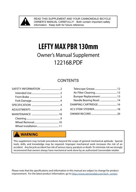
READ THIS SUPPLEMENT AND YOUR CANNONDALE BICYCLE<br />
OWNER’S MANUAL CAREFULLY! Both contain important safety<br />
information. Keep both for future reference.<br />
LEFTY MAX <strong>PBR</strong> <strong>130</strong>mm<br />
Owner’s <strong>Manual</strong> <strong>Supplement</strong><br />
122168.PDF<br />
CONTENTS<br />
safety information ................................ 2<br />
Intended Use............................................... 2<br />
Front Brake .................................................. 2<br />
Fork Damage................................................ 4<br />
specification ................................................ 4<br />
adjustments................................................. 6<br />
MAINTENANCE ..............................................18<br />
Cleaning........................................................ 9<br />
Wheel Removal.........................................10<br />
Wheel installation....................................11<br />
Telescope Grease......................................12<br />
Air Filter Cleaning.....................................13<br />
Bumper Replacement.............................13<br />
Needle Bearing Reset ............................14<br />
DAMPING CARTRIDGE................................16<br />
XC3 STEM-STEERER......................................18<br />
OWNER RECORD............................................20<br />
WARNING<br />
This supplement may include procedures beyond the scope of general mechanical aptitude. Special<br />
tools, skills, and knowledge may be required. Improper mechanical work increases the risk of an<br />
accident. Any bicycle accident has risk of serious injury, paralysis or death. To minimize risk we strongly<br />
recommend that owners always have mechanical work done by an authorized Cannondale retailer.<br />
Please note that the specifications and information in this manual are subject to change for product<br />
improvement. For the latest product information, go to http://www.cannondale.com/tech_center/
safety<br />
information<br />
Intended Use<br />
<strong>Lefty</strong> <strong>PBR</strong> <strong>130</strong>mm is intended for<br />
Condition 4 (All Mountain) riding. Condition<br />
4 symbol shown next figure.<br />
Not Intended<br />
For riding on<br />
rough trails<br />
with medium<br />
obstacles<br />
The <strong>Lefty</strong> <strong>PBR</strong> <strong>130</strong> are not intended for use<br />
in extreme forms of jumping/riding such as<br />
hardcore mountain, Freeriding, Downhill,<br />
North Shore, Dirt Jumping, Hucking etc.<br />
WARNING<br />
UNDERSTAND YOUR FORK AND ITS<br />
INTENDED USE. USING YOUR FORK THE<br />
WRONG WAY IS DANGEROUS.<br />
Industry usage Conditions 1 - 5 are<br />
generalized and evolving. Consult your<br />
Cannondale Dealer about how you intend<br />
to use your bike.<br />
Please read your Cannondale Bicycle<br />
Owner’s <strong>Manual</strong> for more information<br />
about Intended Use and Conditions 1-5.<br />
Front Brake<br />
WARNING<br />
DO NOT RIDE WITHOUT A PROPERLY<br />
MOUNTED, ADJUSTED, AND<br />
FUNCTIONING FRONT BRAKE SYSTEM.<br />
The <strong>Lefty</strong> (disc/caliper) acts as an integral<br />
secondary wheel retention system. If the<br />
system is missing or improperly installed,<br />
or if the wheel hub axle bolt should loosen,<br />
the front wheel could slide off the spindle<br />
end.<br />
When mounting IS compatible brake<br />
systems:<br />
Follow brake manufacturer’s instructions<br />
when mounting the brake caliper to the<br />
spindle brake bosses. Do not modify the<br />
fork in any way.<br />
PLEASE ASK YOUR CANNONDALE<br />
DEALER FOR HELP WHEN INSTALLING<br />
COMPATIBLE FRONT BRAKE SYSTEMS.<br />
Make sure the brake disc can not make contact<br />
with the fork boot. A rotating brake disc can<br />
wear through the boot allowing contaminants<br />
into the fork.<br />
CAUTION<br />
USE ONLY 16mm (Cannondale kit #<br />
LEFTYBOLTS. Longer bolts can result<br />
in contact with the brake rotor causing<br />
severe damage. Check clearance between<br />
the bolt tips and rotor after remounting<br />
the caliper.
122168.PDF<br />
Fork Damage<br />
WARNING<br />
STOP RIDING A DAMAGED FORK IMMEDIATELY.<br />
serious fork damage is present:<br />
1. Any unusual “klunking” or knocking noises.<br />
2. A change in fork travel.<br />
3. An over-extended, elongated, or compressed boot.<br />
4. Changes from the way the fork had been working<br />
5. Loss of adjustment features, oil, or air leakage.<br />
6. Crash or impact damage (deep scratches, gouges, dents, or bending)<br />
The following conditions indicate that<br />
For next items 7-10 please read Inspect For Safety in PART II, Section D. of your Cannondale<br />
Bicycle Owner’s <strong>Manual</strong>. See figure on page 5 in this manual for inspection AREAS I-IV.<br />
7. AREA I - Small cracks under the bolt head of upper and lower clamp bolts. This inspection<br />
requires the removal of the bolts.<br />
8. AREA II - Vertical cracks in the outer tube (where the races and needle bearings run). These<br />
may show as long, straight lines perhaps several lines parallel to each other.<br />
9. AREA III - Horizontal cracks above and below the intersection of the upper and lower<br />
clamps with the outer tube portion of the <strong>Lefty</strong> structure.<br />
10. AREA IV - Vertical cracks at the back of the <strong>Lefty</strong> spindle directly behind the roll-pin. This<br />
may happen in a big event crash and the spindle twists slightly.<br />
HAVE ANY DAMAGED FORK INSPECTED AND DAMAGE REPAIRED BY YOUR<br />
CANNONDALE DEALER. YOU CAN BE SEVERELY INJURED, PARALYZED OR KILLED IN AN<br />
ACCIDENT IF YOU IGNORE THIS WARNING.<br />
The maintenance section of this supplement includes information about regular maintenance<br />
practices that can keep your fork in good operating condition.
specification<br />
TRAVEL<br />
<strong>130</strong>mm<br />
INTENDED USE CONDITION 4 See page 2.<br />
RECOMMENDED SAG 25-30% 32.5-39.0mm<br />
AIR PRESSURE LIMITS<br />
CLAMP WIDTH<br />
ADJUSTMENTS<br />
MAIN SPRING TYPE<br />
NEGATIVE SPRING<br />
MINIMUM<br />
MAXIMUM<br />
137.6mm<br />
163.0mm<br />
REBOUND DAMPING DIAL<br />
LOCKOUT<br />
SOLO AIR<br />
AIR AUTOMATIC<br />
50 psi, 3.4 bar<br />
225 psi, 15.5 bar<br />
4.5” Headtube<br />
5.5” Headtube<br />
4.5 TURNS<br />
PUSH BUTTON LOCK/RELEASE
122168.PDF
adjustments<br />
Air Pressure<br />
For best performance, set the air pressure in your <strong>Lefty</strong> so the sag is 32.5-39mm. Sag is the<br />
distance the fork compresses when you sit on the bike. Sag is set by changing the air pressure<br />
in the fork. The table of values on the next page should be a good starting point. Fine tune sag<br />
by adding or releasing air in small amounts. Add air pressure to decrease sag. Add air pressure<br />
to decrease sag.<br />
1. Remove the Schrader valve cap at the bottom of the fork. Attach a bicycle suspension<br />
pump to the valve end. Pressurize the fork according to your body weight.<br />
2. To fine tune sag. Off the bike, measuring length (A). Next, have someone assist you. Sit<br />
on the bike with your feet on the pedals and hands on handlebar as if you were in a riding<br />
position; measure length (B), the fork compressed under your weight. To calculate the sag,<br />
subtract : A - B = SAG (mm).<br />
CAUTIONS<br />
CLEAN PUMP AND VALVE ARE CLEAN.<br />
Attaching to a dirty valve or with a dirty<br />
pump end can result in pumping the<br />
dirt into the fork. This could result in<br />
damage and air loss.<br />
DO NOT FORCE THE REBOUND DIAL<br />
PAST THE STOP POINTS. USE ONLY<br />
YOUR FINGERS TO TURN.
122168.PDF<br />
Rebound<br />
The red rebound dial at the top of<br />
the fork controls rebound speed,<br />
how fast the fork extends following<br />
compression. There are 4 1/2 turns of<br />
total adjustment.<br />
Turn the dial CLOCKWISE for slower<br />
rebound.<br />
Turn the dial COUNTER-CLOCKWISE for<br />
faster rebound.<br />
Lockout<br />
To lockout the fork - Press the small blue button down with your finger tip. This will trigger the<br />
rebound dial to pop up. Fork travel is locked out when the dial is up. See LOCKED.<br />
To unlock travel - Press the rebound dial down firmly. Fork travel is not locked out when the<br />
buttons are down. See UNOCKED.<br />
If button action begins to stick, (fork will not lock easily) it is likely due to dirt in the rebound and<br />
lockout knob seals. Remove the flat head screw in the center of the blue lock button. Pull the red<br />
rebound knob off the fork and remove the lock button and clean and grease the seal inside the<br />
upper collar and inside the rebound knob.
maintenance<br />
This schedule is intended as a guide only. You must establish a schedule appropriate to your<br />
riding style and conditions.<br />
WHAT TO DO<br />
CHECK FOR DAMAGE<br />
Don’t ride if damage is found. See page 3.<br />
CHECK THE BOOT<br />
Replace the zip ties if loose.<br />
CHECK TIGHTENING TORQUES<br />
Upper/Lower clamp bolts: 9.0 Nm<br />
Wheel Axle Bolt: 15.0 Nm<br />
NORMAL<br />
RACE<br />
(In Hours)<br />
BEFORE AND AFTER EVERY RIDE<br />
AFTER FIRST RIDE<br />
CHECK EVERY 4-5 RIDES<br />
Grease telescope. 50 25<br />
Needle Bearing Reset* 25 25<br />
Clean air filter 25 10<br />
Damping cartridge oil and seal change* 100 25<br />
Inspect, Replace Bumper<br />
AS NEEDED<br />
PROFESSIONAL SERVICE* ANNUAL (Minimum)<br />
Annually, or when problems are indicated you must have your <strong>Lefty</strong> fork serviced through<br />
a Cannondale Dealer or an Authorized Headshok Service Center. Your fork should<br />
be disassembled by a suspension professional and evaluated for internal and external<br />
part wear and damaged parts replaced with new ones. It should also include any work<br />
described in any technical bulletins or product recalls.<br />
WARNING<br />
FREQUENT MAINTENANCE AND INSPECTION IS IMPORTANT TO YOUR SAFETY. YOU<br />
CAN BE SEVERELY INJURED, PARALYZED OR KILLED RIDING ON A BROKEN OR POORLY<br />
MAINTAINED FORK. Ask your Cannondale Dealer to help you develop a complete fork<br />
maintenance program, one that suits where and how you ride.
122168.PDF<br />
Riding in Wet, Humid, or Coastal Conditions<br />
Before and after rides, frequently, inspect and renew grease under fork boot<br />
and service the air filter. Inspect the boot for rips and tears. Check the folds.<br />
If the boot is damaged or not attached securely by the clamps/zip ties ,<br />
water or contaminants can enter. The boot should be removed and the fork<br />
should be immediately dried and re-greased to stop any damage occurring<br />
due to moisture.<br />
ANYTIME THE FORK BECOMES SUBMERGED<br />
Stop riding it. The fork is not water tight. A moving submerged fork can<br />
accumulate water inside. If your fork has been submerged, you should<br />
perform checks immediately.<br />
DO NOT STORE YOUR LEFTY FOLLOWING A WET RIDE WITHOUT FIRST<br />
PERFORMING THE CHECKS ABOVE. SERIOUS DAMAGE CAN OCCUR.<br />
Cleaning<br />
Clean using only a mild soap and water solution. Clean water and common liquid dish washing<br />
soap will work best. Be sure to cover the adjusters with a clean plastic bag secured with a rubber<br />
band or masking tape. Spray off heavy dirt before wiping. Spray indirectly.<br />
CAUTION<br />
DO NOT USE A PRESSURE WASHER. Use a low pressure garden hose. Power washing will<br />
force contaminants into the fork promoting corrosion, immediately damaging, or result in<br />
accelerated wear. Don’t dry with compressed air for the same reason.<br />
PLEASE NOTE<br />
Cannondale provides professional services through Cannondale dealers for Headshok /<strong>Lefty</strong><br />
suspension forks. Please ask your dealer about the service programs available for your model<br />
fork.
Wheel Removal<br />
1. Loosen the brake caliper mounting bolts.<br />
Tilt the lower caliper bolt out of the<br />
boss so the caliper is up out of the<br />
way of the disc. Snug up on the<br />
upper bolt to hold caliper in place.<br />
Take note of brake alignment shims<br />
between brake bosses and the caliper. Be<br />
sure to reposition correctly.<br />
2. Turn the hub extraction bolt counterclockwise<br />
(ccw) to remove the wheel.<br />
CAUTION<br />
1. Make sure the bolt is completely<br />
disengaged before attempting<br />
to remove the wheel. Never try<br />
to pull the wheel off forcefully.<br />
2. When the wheel is off, to keep<br />
dirt out, cover the hub opening.<br />
3. Protect spindle from damage<br />
when wheel is removed.<br />
Continue turning the bolt until the wheel<br />
can be removed easily from the spindle.<br />
10
122168.PDF<br />
Wheel Installation<br />
1. Inspect inside the wheel hub for<br />
contamination and and the condition<br />
of the hub seal. Take corrective action if<br />
necessary.<br />
Wipe the spindle clean with a dry shop<br />
towel and apply a high-quality bike grease<br />
to the spindle bearing lands and end<br />
threads. See next Figure.<br />
2. Slide the wheel straight onto the spindle<br />
so, the larger hub bearing starts to position<br />
on it spindle seat. At this point, the axle<br />
bolt threads can correctly engage the<br />
threaded spindle if the wheel is held on<br />
straight.<br />
NOTE: Install the front wheel by positioning<br />
the bike horizontally with the spindle facing<br />
up. Then place the hub straight down onto<br />
the spindle, and tighten the axle bolt.<br />
3. When the axle bolt threads engage the<br />
spindle, turn the bolt clockwise with finger<br />
force slowly to allow the hub bearings<br />
to slide onto the spindle bearing seats.<br />
WARNING<br />
Do not contaminate brake caliper, pads,<br />
or rotor with grease.<br />
CAUTION<br />
LOCATE DISC BETWEEN THE PADS.<br />
Replace shims that are in use, be sure the<br />
shims are positioned between the caliper<br />
(adapter if any) and inner face of the fork<br />
mounts, not under the head of the caliper<br />
bolts.<br />
USE ONLY 16mm (Cannondale kit #<br />
LEFTYBOLTS. Longer bolts can result<br />
in contact with the brake rotor causing<br />
severe damage. Check clearance between<br />
the bolt tips and rotor after remounting<br />
the caliper.<br />
Once the hub has been drawn onto the<br />
hub completely, use torque wrench to<br />
tighten to final 15.0 N•m (133.0 In•Lbs).<br />
4. Reinstall the brake caliper. Tighten bolts to<br />
78.0 In•Lbf (9.0 N•m).<br />
5. Spin the wheel to make sure it moves<br />
freely. Be sure to test the brakes for<br />
proper operation before riding.<br />
11
Grease Telescope<br />
1. Remove the front wheel.<br />
2. Carefully release the upper and lower zip<br />
ties securing the fork boot. If the boot is<br />
secured with a band clamp, loosen and<br />
remove them.<br />
3. Lift the unsecured boot up to expose the<br />
inner tube.<br />
4. Wipe off the old grease with a dry shop<br />
towel.<br />
5. Re-apply a fresh heavy coating of grease.<br />
Any clean high-quality bicycle bearing<br />
grease selected for riding temperatures<br />
and environment can be used.<br />
We assemble forks at our factory<br />
using Royal Purple Ultra Performance<br />
Grease NLGI #2 (ISO 46 BASE).<br />
Cycle the fork several times between<br />
applying grease to the new grease is<br />
worked into the bearings.<br />
6. Reposition the boot and replace the zip<br />
ties. Make sure the zip ties are very tight.<br />
Loose zip ties may allow water or dirt to<br />
pass behind the boot.<br />
WARNINGS<br />
CHECK THE BOOT BEFORE EACH RIDE.<br />
DON’T RIDE IF IT IS DAMAGED.<br />
HAVE IT REPLACED WITH A NEW ONE.<br />
12
122168.PDF<br />
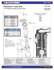
NO. ORDER NO. KIT DESCRIPTION<br />
1 KF209/ KIT,COLLAR,LOWER,CRB,CLIP+BUSH<br />
HDR2M/020<br />
RACE INNER 11.378 X .020in [289.0 X .53mm]<br />
(Qty 4)<br />
HDR2M/021<br />
RACE INNER 11.378 X .021in [289.0 X .56mm]<br />
(Qty 4)<br />
2<br />
HDR2M/022<br />
RACE INNER 11.378 X .022in [289.0 X .58mm]<br />
(Qty 4)<br />
HDR2M/023<br />
RACE INNER 11.378 X .023in [289.0 X .61mm]<br />
(Qty 4)<br />
HDR2M/024<br />
RACE INNER 11.378 X .024in [289.0 X .635mm]<br />
(Qty 4)<br />
3 HD161/ LEFTY NEEDLE BEARINGS (QTY 4)<br />
4 HDR2N/024 RACE OUTER<br />
Air Filter<br />
To clean, release the upper and lower clamps or zip tie and slide the filter cover up off the foam.<br />
Slide the foam up the outer tube and cover the two small holes in the outer tube to prevent<br />
water from getting inside the fork. Clean with warm soapy water. Rinse with clean water and<br />
allow the foam to dry completely. Then, massage in a high-quality foam air filter oil before reassembly.<br />
NOTE: The small holes at the base of the filter cover should remain clear and be positioned to<br />
the sides of bike and not to the front or back to minimize the chance dirt thrown by the wheels<br />
will plug the holes.<br />
Bumper Replacement<br />
Replace the frame bumper with a new one if it ever becomes damaged, torn, or missing. To<br />
remove it, remove the band from the bumper groove and unwrap the bumper.<br />
13
Needle Bearing Reset<br />
Needle bearing resets must be performed as maintenance. Migrated needle bearings are<br />
bearings that are no longer aligned together. Riding a fork with migrated needle bearings for<br />
extended periods can result in damage.<br />
TO BE PERFORMED ONLY BY A PROFESSIONAL BIKE MECHANIC:<br />
Annually as part of your annual fork overall maintenance. See schedule on page 8.<br />
Whenever free length is less than specified<br />
If the fork produces a top out noise when fully extended<br />
If normal fork travel becomes reduced<br />
To reset<br />
1. Release all air pressure through Schrader valve in bottom of fork.<br />
2. Remove the outer collar the Shimano tool TL-FC32. Turn counter-clockwise.<br />
3. Compress the telescope and remove the two split rings from the top cap.<br />
4. Fully extend the fork, and measure from top edge of outer tube to bottom edge of spindle.<br />
See right. If the length is out of specification do the following:<br />
Firmly extend the telescope until it stops (tip - listen for the knocking at full extension to change<br />
from a hollow sound to a solid sound - this indicates full extension has been achieved). Do this<br />
several times using only moderate force, extend the lower fork leg using a pumping action.<br />
After, you have performed this action several times, re-measure.<br />
CAUTION<br />
If fork is out of range following reset attempt, it may be damaged internally. The fork<br />
should be disassembled and inspected by a professional mechanic before it is ridden.<br />
5. Reassemble.<br />
NOTE: If migration re-occurs frequently (immediately after resetting), the cause could be<br />
damage present in the inner or outer races, bearings/cages or other fork parts. Inspection<br />
and replacement of damage parts will be required to correct a persistent problem with<br />
bearing migration.<br />
14
122168.PDF<br />
4 NEEDLE BEARING CAGES<br />
NEEDLE BEARINGS<br />
INSIDE THIS PART<br />
OF FORK.<br />
RESET BY FULLY<br />
EXTENDING LOWER<br />
LEG<br />
15
DAMPING CARTRIDGE<br />
NO.<br />
DESCRIPTION<br />
1 SPECTRO 85/150 OIL (cc)<br />
2 2-006 O-RING 2.90 ID X 1.78 W<br />
3 2-010 O-RING 6.07 ID X 1.78 W<br />
4 2-011 O-RING 7.65 ID X 1.78 W<br />
5 2-012 O-RING 9.25 ID X 1.78 W<br />
6 2-013 O-RING 10.82 ID X 1.78 W<br />
7 2-014 O-RING 12.42 ID X 1.78 W<br />
8 2-018 O-RING 18.77 ID X 1.78 W<br />
9 2-112 O-RING 12.37 ID X 2.62 W<br />
10 2-117 O-RING 20.29 ID X 2.62 W<br />
11 O-RING 2.00 ID X 1.00 W<br />
12 O-RING 9.00 ID X 1.00 W<br />
13 O-RING 8.00 ID X 1.50 W<br />
14 SHCS M2 5 X 5<br />
15 BLEED SCREW M2 5 X 4 FHP<br />
16 SFHS M X 8<br />
17 COMPRESSION SHIM STACK (SEE TABLE)<br />
18 REBOUND SHIM STACK (SEE TABLE)<br />
19 CHROME STEEL BALL 3MM<br />
20 DLR 110 OIL CAP<br />
21 DLR 110 PRESSURE COMP PISTON<br />
22 DLR 110 PRESSURE COMP SPRING<br />
23 DLR 110 PISTON SPACER<br />
24 DLR 110 BUMPER<br />
25 DLR 110 PISTON RING<br />
26 DLR 110 MAIN PISTON<br />
27 DLR 110 OIL CYLINDER WASHER<br />
28 07 DLR 100 OUTER CAP<br />
29 BALL LOCK UPPER SHAFT<br />
30 BALL LOCK POPET<br />
31 BALL LOCK INNER SHAFT<br />
32 BALL LOCK KNOB SHAFT<br />
33 BALL LOCK REBOUND KNOB<br />
34 BALL LOCK RELEASE BUTTON<br />
35 BALL LOCK THRU SHAFT<br />
36 BALL LOCK LOCKOUT PISTON<br />
37 BALL LOCK LOCKOUT ROD<br />
38 BALL LOCK NEEDLE PINNED<br />
39 BALL LOCK PISTON CONNECT<br />
40 BALL LOCK LOWER SHAFT <strong>130</strong><br />
41 BALL LOCK CONNECT BUSHING<br />
42 SOLO AIR MAIN PISTON R3<br />
43 SOLO AIR PISTON SUPPORT R3<br />
44 SOLO AIR UPPER SEAL <strong>130</strong><br />
45 SOLO AIR BUMPER PLATE<br />
46 SOLO AIR NEGATIVE BUMPER<br />
47 RETAINING RING EXT. M10<br />
48 PIN ROLL M2 x 10<br />
49 M1.6 x 16 PAN HEAD SCREW<br />
50 LOCKOUT ROD SPRING<br />
51 BALL LOCK SPRING RELEASE<br />
52 #5 WASHER<br />
53 CRESENT SHAPE SPRING WASHER<br />
54 BALL LOCK OIL CYLINDER <strong>130</strong><br />
55<br />
1/2” U-CUP PARKER<br />
#N4180-A80-8404-00500<br />
56 WASHER<br />
57 SPLIT RING<br />
SHIM STACKS FROM PISTON OUT<br />
COMPRESSION<br />
REBOUND<br />
16 X 0.152 18 X 0.102<br />
18 X 0.102 16 X 0.102<br />
14 X 0.152 14 X 0.102<br />
AIR SPRING VOLUMES:<br />
MAIN SPRING = 94905mm^3<br />
NEGATIVE SPRING = 33405 mm^3<br />
EFFECTIVE LENGTH:<br />
MAIN SPRING = 190.0mm<br />
NEG SPRING = 66.9mm<br />
Assembly Note<br />
NLGI 2 synthetic grease is to be applied to all seal<br />
grooves, surfaces, and glands.<br />
NO. ORDER NO. KIT DESCRIPTION<br />
KH041/<br />
<strong>130</strong> <strong>PBR</strong> CARTRIDGE<br />
HD226/<br />
GOLDEN SPECTRO 1 US QT.<br />
2, 3, 4, 5, 6, 7, 8, 9, 10, 11, 12, 13,<br />
15, 55<br />
KH042/<br />
<strong>PBR</strong> <strong>130</strong> SEAL KIT<br />
4, 7, 9, 10, 42, 43, 44, 45, 46, 47, 53 KH043/ <strong>PBR</strong> <strong>130</strong> AIR PISTON KIT<br />
6, 16, 33, 34 KH044/ <strong>PBR</strong> <strong>130</strong> KNOBS<br />
57 KF205/ 2 SPLT RINGS<br />
58 HD187/ 1/2” SHAFT CLAMP<br />
59 HDTL168/ OIL CAP INSTALL<br />
60 KH004/ OIL CAP WRENCH<br />
61 HDTL146/ CARTRIDGE REMOVAL<br />
CANNONDALE CARTRIDGE TOOLS<br />
16
17<br />
122168.PDF
xc3 stem-steerer<br />
The following procedure should be completed<br />
by a professional bike mechanic.<br />
Installation<br />
1. Loosen both clamp bolts .<br />
3. Position the <strong>Lefty</strong> clamps onto the<br />
headtube assembly as shown.<br />
4. Insert Cannondale tool KT020/ through the<br />
bottom clamp, into the head tube, and out<br />
the upper clamp.<br />
5. Make sure the plastic ring is on the stem.<br />
Insert the bottom of the stem-steerer onto<br />
the top of the tool.<br />
6. Remove the cap from the top of the<br />
steerer. Use a rubber mallet to drive the<br />
stem-steerer into the head tube until it<br />
stops. Return the cap.<br />
7. Clean and apply grease to the steerer bolt<br />
threads and install into the bottom of the<br />
stem-steerer. The bolt is a structural part<br />
that threads into the bottom of the stemsteerer.<br />
Align handlebar and tighten the<br />
bolt to 9 N•m.<br />
8.. Tighten the upper and lower clamp bolts<br />
to 9 N•m.<br />
Removal<br />
1 Loosen upper and lower clamp bolts.<br />
2. Remove steerer bolt. Use a 5mm Allen key;<br />
turn counter-clockwise.<br />
3. Insert the small end of KT020/ into the<br />
bottom of the stem-steerer and drive the<br />
stem-steerer up out of the head tube.<br />
18
122168.PDF<br />
XC3 Stem-Steerer kits in<br />
various sizes are available<br />
through your Cannondale<br />
Dealer.<br />
NOTES:<br />
1. When removing or installing<br />
steerer bolt, insert 5mm Allen key<br />
completely to prevent stripping the<br />
bolt.<br />
2. The drain hole enables accumulated<br />
moisture to drain out. Use a<br />
toothpick to keep it clear.<br />
WARNING<br />
The steerer bolt is a structural<br />
part and must be installed.<br />
19
owner record<br />
Record maintenance history, service, or set up information .<br />
DATE<br />
WORK PERFORMED<br />
20