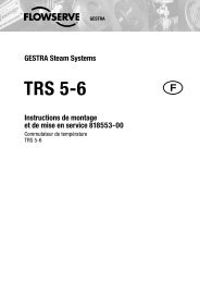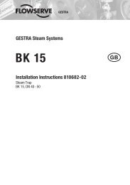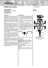
URB 1 - Flowserve Corporation
URB 1 - Flowserve Corporation
URB 1 - Flowserve Corporation

You also want an ePaper? Increase the reach of your titles
YUMPU automatically turns print PDFs into web optimized ePapers that Google loves.
<strong>URB</strong> 1<br />
<br />
Installation Instructions 810375-03<br />
Operating Terminal and Display Unit <strong>URB</strong> 1<br />
1
Contents<br />
Important Notes<br />
Page<br />
Usage for the intended purpose ......................................................................................8<br />
Safety note ......................................................................................................................8<br />
Explanatory Notes<br />
Scope of supply ..............................................................................................................8<br />
System description ......................................................................................................8, 9<br />
Function ..........................................................................................................................9<br />
Technical data ...............................................................................................................10<br />
Installation<br />
<strong>URB</strong> 1 ...........................................................................................................................10<br />
Example of installation ................................................................................................ 79<br />
Wiring<br />
Wiring diagram ........................................................................................................ 4, 12<br />
Basic Settings<br />
CAN bus ...................................................................................................................... 13<br />
Node ID for GESTRA bus-based devices <strong>URB</strong> 1 ....................................................... 13<br />
Factory set default values ............................................................................................ 13<br />
Adjusting display brightness ................................................................................. 14, 15<br />
Changing factory set node ID of <strong>URB</strong> 1 / adjusting & changing node ID of <strong>URB</strong> 1 . 16–18<br />
Possibilities to display bus devices ............................................................................. 18<br />
Setting / changing node IDs of bus-based equipment .......................................... 19–22<br />
Visual display / parameterisation of bus-based equipment ................................. 23–28<br />
0 %/100 % calibration for capacitance level monitoring system .......................... 29–31<br />
Calibrating feedback potentiometer of an external control valve ......................... 32–35<br />
Establishing switchpoints and proportional coefficient X P<br />
.................................... 36–39<br />
Adjusting sensitivity of response ........................................................................... 40, 41<br />
Setting relay delay times ....................................................................................... 42–44<br />
Adjusting conductivity controller ........................................................................... 45–57<br />
Adjusting LIN (linear) temperature compensation ................................................ 58–60<br />
Adjusting NORM (standard curve) temperature compensation ........................... 61–65<br />
Enabling AUTO temperature compensation ............................................................ 66, 67<br />
Disabling temperature compensation ................................................................... 68, 69<br />
2
Contents<br />
Operation<br />
Manual operation via external control valve ............................................................... 70<br />
Stand-by operation with the steam boiler disconnected ............................................. 71<br />
System Malfunctions<br />
Page<br />
Systematic malfunction analysis for troubleshooting .................................................. 72<br />
Fault finding list ...................................................................................................... 73, 74<br />
Annex<br />
Establishing / changing node ID ................................................................................. 75<br />
Factory set node IDs .............................................................................................. 75, 76<br />
Table: standard curves ................................................................................................ 77<br />
Declaration of conformity ............................................................................................. 78<br />
3
Wiring Diagram<br />
Fig.1<br />
Terminating resistor 120 Ω,<br />
Paired cable<br />
Operating<br />
terminal<br />
<strong>URB</strong> 1<br />
NRS<br />
CEP*)<br />
Level switch<br />
Conductivity<br />
controller<br />
LRR 1-40<br />
Conductivity<br />
electrode<br />
LRG 16-40<br />
Electrode<br />
NRG . . .<br />
Voltage supply<br />
Terminating resistor<br />
120 Ω<br />
CAN data line<br />
Terminating resistor<br />
120 Ω<br />
*) CEP = central earthable point<br />
Fig. 2<br />
4
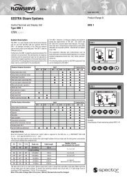
Functional Elements<br />
6<br />
Fig. 3 1 2 3 4 5<br />
5
Functional Elements<br />
B<br />
7<br />
A<br />
A<br />
Fig. 4<br />
6
Key<br />
1<br />
2<br />
3<br />
4<br />
5<br />
6<br />
7<br />
Program button for switching between operating mode and parameterisation mode<br />
Increase button<br />
Decrease button<br />
Enter button<br />
Manual / automatic button<br />
Illuminated LCD display, resolution 128 x 64 pixels<br />
Code switch for baud rate setting<br />
A<br />
B<br />
Fixing screws for panel mounting<br />
Five-pole connector<br />
7
Important Notes<br />
Usage for the intended purpose<br />
Use operating terminal & display unit <strong>URB</strong> 1 only in conjunction with GESTRA<br />
Spector bus systems (CANopen).<br />
Safety Note<br />
Use operating terminal and display unit <strong>URB</strong> 1 only for operating and viewing<br />
GESTRA CAN bus systems.<br />
The equipment must only be installed by qualified staff.<br />
Qualified staff are those persons who – through adequate training in electrical<br />
engineering, the use and application of safety equipment in accordance with<br />
regulations concerning electrical safety systems, and first aid & accident prevention –<br />
have achieved a recognised level of competence appropriate to the installation and<br />
commissioning of this device.<br />
Explanatory Notes<br />
Scope of supply<br />
<strong>URB</strong> 1<br />
1 Operating terminal and display unit <strong>URB</strong> 1 (in plastic case)<br />
2 Fixing screws for panel mounting<br />
1 Installation manual<br />
System description<br />
The <strong>URB</strong> 1 is a user-friendly operating terminal and display unit for GESTRA CAN<br />
bus systems using the CANopen protocol. The equipment makes retrieving and<br />
processing standard functions of associated system components very easy.<br />
In addition, the <strong>URB</strong> 1 simplifies the parameterisation procedure: The switchpoints,<br />
proportional band and response sensitivity can be adjusted by means of the keypad<br />
regardless of the actual level. The energizing and de-energizing times of the relays<br />
can be set individually for their respective switchpoints.<br />
The following tables specifiy the GESTRA systems that can be displayed by the<br />
<strong>URB</strong> 1.<br />
8
Explanatory Notes – continued –<br />
System description – continued –<br />
Standard display information<br />
Level<br />
Conductivity<br />
NRS 1-40 NRS 1-41 NRS 1-42 NRS 2-40 NRR 2-40 LRR 1-40<br />
Actual value (bar chart) ● ● ●<br />
Actual value (numerical value) ● ● ●<br />
Switchpoint (symbol) ● ● ● ●<br />
High level alarm (electrode HW) ● ● ● ●<br />
Low level alarm (electrode LW) ● ● ● ●<br />
Manual/automatic operation ● ● ●<br />
Stand-by mode<br />
●<br />
Unit [µS/cm] or [ppm]<br />
●<br />
Low level limit<br />
●<br />
High level limit<br />
●<br />
Alarm (warning triangle) ● ●<br />
Further display information<br />
Level<br />
Conductivity<br />
NRS 1-40 NRS 1-41 NRS 1-42 NRS 2-40 NRR 2-40 LRR 1-40<br />
Actual value (continuous) ● ● ●<br />
Switchpoints ● ● ● ●<br />
Setpoint ● ●<br />
Deviation ● ●<br />
Valve position ● ●<br />
Intermittent blowdown<br />
●<br />
Intermittent blowdown interval<br />
●<br />
Purging pulse 24 h<br />
●<br />
Current CAN bus addresses ● ● ● ● ● ●<br />
Function<br />
The <strong>URB</strong> 1 communicates with other GESTRA system components via a designated<br />
CAN bus using the CANopen protocol to DIN ISO 11898.<br />
The <strong>URB</strong> 1 can also be used to operate and display further system components<br />
during operation.<br />
■ Capacitance level switch type NRS 2-40 CANopen<br />
■ Level controller type NRR 2-40 CANopen<br />
■ Conductivity level switch type NRS 1-42 CANopen<br />
■ Low-level alarm to TRD 604/EN type NRS 1-40 CANopen<br />
■ High-level alarm to TRD 604/EN type NRS 1-41 CANopen<br />
■ Conductivity controller and limiter to TRD 604/EN type NRS 1-41 CANopen<br />
9
Explanatory Notes – continued –<br />
Technical data<br />
Type approval no.<br />
TÜV · 98-399 (level)<br />
TÜV · WÜL · 02-007 (conductivity)<br />
Input<br />
Power supply: 18 V – 36 V DC<br />
Interface for CAN bus using CANopen protocol to DIN ISO 11898<br />
Output<br />
Interface for CAN bus using CANopen protocol to DIN ISO 11898<br />
Indicators and adjustors<br />
1 illuminated display, resolution: 128 x 64 pixels<br />
5 push buttons<br />
1 three-pole code switch for baud rate setting<br />
Supply voltage<br />
18 V – 36 V DC<br />
Protection<br />
Front panel: IP 54 to DIN EN 60529<br />
Back: IP 00 to DIN EN 60529<br />
Admissible ambient temperature<br />
0 °C – 55 °C<br />
Case material<br />
Front face: Aluminium with polyester membrane<br />
Casing: Noryl GFN 2 SE 1, glass-fibre reinforced<br />
Weight<br />
Approx. 0.3 kg<br />
Installation<br />
<strong>URB</strong> 1<br />
Panel mounting<br />
1. Provide panel cut-out, dimensions: 92 +0.8 x 92 +0.8 .<br />
2. Install <strong>URB</strong> 1 using the fixing clips supplied with the equipment.<br />
10<br />
Tool<br />
■ Screwdriver (5.5/100)
Wiring<br />
Note that multi-core control cable with conductors linked in pairs, e. g. UNITRONIC ®<br />
BUS CAN 2 x 2 x .. mm 2 or RE-2YCYV-fl 2 x 2 x .. mm 2 .<br />
The baud rate (data transfer rate) dictates the cable length between the bus nodes<br />
and the total power consumption of the sensors dictates the conductor size.<br />
S 8 S 9 S 10<br />
OFF<br />
ON<br />
OFF<br />
ON<br />
OFF<br />
ON<br />
ON<br />
ON<br />
OFF<br />
OFF<br />
ON<br />
ON<br />
Wiring diagram<br />
OFF<br />
OFF<br />
ON<br />
ON<br />
ON<br />
ON<br />
Baud rate<br />
For wiring diagram refer to page 4.<br />
Cable length<br />
250<br />
kBit/ s 125 m<br />
Factory settings<br />
Number of pairs<br />
and conductor size [mm2]<br />
2 x 2 x 0,34<br />
125<br />
kBit/ s 250<br />
m<br />
2 x 2 x 0, 5<br />
100<br />
kBit/ s 335<br />
m<br />
2 x 2 x 0,75<br />
50<br />
kBit/ s 500 m<br />
20<br />
kBit/ s 1000 m<br />
10<br />
kBit/ s 1000 m<br />
on request, dependent on<br />
bus configuration<br />
The baud rate is set via a code switch. Reduce baud rate if cable is longer than<br />
specified in the table above. Make sure that all bus nodes feature the same settings.<br />
To protect the switching contacts fuse circuit with 2.5 A (anti-surge fuse) or according<br />
to TRD regulations (1.0 A for 72 hrs operation).<br />
When a max. cable length of more than 125 m (up to 1000 m) is desired, make<br />
sure to modify the baud rate accordingly. Refer to pages 75 and 76 for more<br />
details.<br />
Attention<br />
■ Wire equipment in series. Star-type wiring is not permitted.<br />
■ Interlink screens of control cables such that electrical continuity is<br />
ensured and connect them once to the central earthing point (CEP).<br />
■ If more than one system component is connected to a CAN bus<br />
network provide the first and last equipment with a terminating resistor<br />
of 120 Ω, Fig. 2<br />
■ The CAN bus line must not be interrupted while operating with one or<br />
more system components.<br />
Any interruption will open the control circuit!<br />
If the switching controller has to be replaced be sure to remove first<br />
the terminal strips B , Fig. 4<br />
Note: Make sure that all system components connected are not<br />
operating before removing the CAN bus line from the terminal strip!<br />
UNITRONIC ® is a registered trademark of LAPP Kabelwerke GmbH, Stuttgart.<br />
11
Wiring – continued –<br />
Tools<br />
Note<br />
■ Connect screen only to terminal 3, ensuring electrical continuity and<br />
connect equipment once to the central earthing point (CEP).<br />
■ The loop resistance must be under 10 Ω.<br />
■ The rated voltage is stated on the name plate.<br />
■ Despite correct wiring H.F. interference caused by the installation may<br />
lead to system breakdowns and malfunction messages. If necessary<br />
refer to the fault finding lists of the respective bus equipment.<br />
■ Screwdriver for slotted screws, size 2.5, completely insulated according to<br />
VDE 0680<br />
12
Basic Settings<br />
CAN-Bus<br />
All level and conductivity controllers and associated electrodes are interconnected by<br />
means of a CAN bus using the CANopen protocol. Every item of equipment features<br />
an electronic address (node ID). The four-core bus cable serves as power supply and<br />
data highway for high-speed data exchange.<br />
The CAN address (node ID) can be set between 60 and 123.<br />
The <strong>URB</strong> 1 is configured at our works and ready for service with other GESTRA<br />
system components without having to set the node ID.<br />
If several systems of the same kind are to communicate in one CAN bus<br />
network, be sure to assign one node ID for each individual system component<br />
(e. g. controller). Refer to page 75 and 76 for more information.<br />
Node ID for GESTRA bus-based device <strong>URB</strong> 1<br />
Example: Conductivity monitoring and control<br />
Example: Level monitoring and control<br />
Factory set default values<br />
The <strong>URB</strong> 1 features the following factory default settings:<br />
■ Baud rate: 250 kb/s<br />
■ Node ID: 060 (Do not change this node ID unless required; highest permissible<br />
setting: 123)<br />
13
Basic Settings – continued –<br />
Adjusting display brightness<br />
The brightness of the LCD display can be<br />
adjusted as necessary.<br />
Press and hold the button for a few<br />
seconds.<br />
The <strong>URB</strong> 1 enters the address<br />
parameterisation mode.<br />
several times briefly<br />
Press button<br />
the brightness.<br />
several times to reduce<br />
several times briefly<br />
14
Basic Settings – continued –<br />
Adjusting display brightness – continued –<br />
Press button several times to<br />
increase the brightness.<br />
several times briefly<br />
Press button briefly to save settings<br />
and return to the main window.<br />
twice briefly<br />
15
Basic Settings – continued –<br />
Changing factory set node ID of the <strong>URB</strong> 1 / Adjusting & changing node ID<br />
The factory set node ID of the <strong>URB</strong> 1 is<br />
“060”. Node IDs below this value are<br />
reserved for other GESTRA bus<br />
components.<br />
If additional operating terminals type <strong>URB</strong> 1<br />
are used in a CAN bus system, you have to<br />
set their node IDs to values above “060”.<br />
Note that the newly established node IDs<br />
must not be identical with node IDs of other<br />
bus components.<br />
Press and hold button for a few<br />
seconds to enter the address<br />
parameterisation mode.<br />
a few seconds<br />
Press button briefly to activate the<br />
line selection mode.<br />
briefly<br />
16
Basic Settings – continued –<br />
Changing factory set node ID of the <strong>URB</strong> 1 / Adjusting & changing node ID – continued –<br />
Press button briefly to activate the line<br />
editing mode.<br />
Use button or to increase or<br />
decrease the first digit.<br />
flashing<br />
briefly<br />
Press button briefly to move the<br />
cursor two steps further.<br />
flashing<br />
twice briefly<br />
Press button<br />
digit “1”.<br />
once briefly to select the<br />
flashing<br />
once briefly<br />
17
Basic Settings – continued –<br />
Changing factory set node ID of the <strong>URB</strong> 1 / Adjusting & changing node ID – continued –<br />
Press button briefly to activate the line<br />
selection mode.<br />
In our example the node ID was set to<br />
“061”.<br />
briefly<br />
Press button twice briefly to save<br />
settings and return to the main window.<br />
twice briefly<br />
Possibilities to display bus devices<br />
The <strong>URB</strong> 1 can display only one level monitoring device, one low-level alarm, one<br />
high-level alarm and one conductivity monitoring device per vessel (e. g. steam<br />
boiler or feedwater deaerator).<br />
If the monitoring systems of more than one vessel are to be displayed, provide one<br />
<strong>URB</strong> 1 per vessel.<br />
18
Basic Settings – continued –<br />
Setting / changing node IDs of bus-based equipment<br />
The standard default node ID setting of all<br />
bus devices that can be displayed is “OFF”.<br />
This setting acts as a wild card for all bus<br />
devices which are not displayed with the<br />
<strong>URB</strong> 1.<br />
For each bus device that shall be displayed<br />
by the <strong>URB</strong> 1 a node ID has to be<br />
established manually.<br />
We recommend to accept the factory set<br />
node IDs of GESTRA bus devices. For the<br />
relevant node ID setting please refer to the<br />
corresponding installation manual of the<br />
device.<br />
Press button briefly to show the<br />
address list and activate the<br />
parameterisation mode.<br />
briefly<br />
Press button briefly to activate the line<br />
selection mode.<br />
briefly<br />
19
Basic Settings – continued –<br />
Setting / changing node IDs of bus-based equipment – continued –<br />
Press button briefly to activate the line<br />
editing mode.<br />
Use button or to increase or<br />
decrease the first digit.<br />
flashing<br />
briefly<br />
Press button<br />
digit “0”.<br />
once briefly to select the<br />
flashing<br />
once briefly<br />
Press button briefly to move the<br />
cursor one step further.<br />
flashing<br />
briefly<br />
Press button<br />
the digit “0”.<br />
twice briefly to select<br />
flashing<br />
20<br />
twice briefly
Basic Settings – continued –<br />
Setting / changing node IDs of bus-based equipment – continued –<br />
Press button briefly to move the<br />
cursor one step further.<br />
flashing<br />
briefly<br />
Press button seven times briefly to<br />
select the digit “1”.<br />
flashing<br />
7 times briefly<br />
Press button briefly to activate the line<br />
selection mode.<br />
briefly<br />
Press button once briefly to move to<br />
the next line.<br />
The node ID of the NRS 1-41 can now<br />
be adjusted.<br />
once briefly<br />
21
Basic Settings – continued –<br />
Setting / changing node IDs of bus-based equipment – continued –<br />
Press button briefly to activate the<br />
parameterisation mode.<br />
In this example the node IDs of all bus<br />
devices have already been adjusted.<br />
If the display of the NRS 1-42 is required<br />
set the node IDs of the NRS 2-40 and<br />
NRR 2-40 to “OFF”.<br />
briefly<br />
Press button twice briefly to save the<br />
settings and return to the main window.<br />
twice briefly<br />
22
Basic Settings – continued –<br />
Visual display / Parameterisation of bus devices<br />
The split-screen display window shows which<br />
GESTRA bus devices can be indicated:<br />
■ High-level limiter type NRS 1-41<br />
■ Low-level limiter type NRS 1-40<br />
■ Level switch type NRS 2-40<br />
■ Level controller type NRR 2-40<br />
■ Conductivity controller type LRR 1-40<br />
Press button briefly to enter the display<br />
window of the level controller NRR 2-40.<br />
1<br />
2<br />
3<br />
4<br />
5<br />
6<br />
Actual level (graphical representation)<br />
Actual level (percentage)<br />
Setpoint deviation<br />
Proportional band X p<br />
Switchpoints NRR 2-40<br />
Valve position<br />
1<br />
4 5<br />
2 3<br />
6<br />
briefly<br />
Press button briefly to enter the display<br />
window of the level switch NRS 2-40.<br />
1 Actual level (graphical representation)<br />
2 Actual level (percentage)<br />
3 Control unit 2 highlighted<br />
4 Switchpoints for control unit 2<br />
5 Low-level signal<br />
(flashes in the event of an LW alarm)<br />
6 High-level signal<br />
(flashes in the event of an HW alarm)<br />
6<br />
1<br />
3 4<br />
2<br />
5<br />
briefly<br />
LW = low water (limiter NRS 1-40)<br />
HW = high water (limiter NRS 1-41<br />
23
Basic Settings – continued –<br />
Visual display / Parameterisation of bus devices – continued –<br />
Press button briefly to enter the<br />
parameterisation mode for the following<br />
settings:<br />
■ 0 % – 100 % calibration NRG 26-40<br />
■ Switchpoints NRR 2-40<br />
■ Proportional band NRR 2-40<br />
■ Switchpoints NRS 2-40<br />
briefly<br />
Press button briefly to enter the<br />
parameterisation mode for the following<br />
settings:<br />
■ Relay energizing delay times<br />
■ Relay de-energizing delay times<br />
briefly<br />
Press button briefly to enter the error<br />
messages window.<br />
For more information see section<br />
Malfunction, Troubleshooting, Fault<br />
Finding List on pages 72 and 74.<br />
briefly<br />
Press button<br />
main window.<br />
1<br />
2<br />
briefly to return to the<br />
Actual conductivity value<br />
Actual conductivity<br />
(graphical representation)<br />
1<br />
2<br />
24<br />
briefly
Basic Settings – continued –<br />
Visual display / Parameterisation of bus devices – continued –<br />
Press button briefly to enter the display<br />
window of the conductivity controller LRR 1-40.<br />
1<br />
2<br />
3<br />
4<br />
5<br />
6<br />
Actual conductivity value<br />
Conductivity setpoint<br />
MAX conductivity value<br />
24 h purging pulse for continuous<br />
blowdown valve<br />
Operating position of continuous<br />
blowdown valve<br />
Valve position of continous blowdown valve<br />
Press button briefly to enter the<br />
parameterisation mode for the following<br />
settings:<br />
■ µS/cm or ppm<br />
■ Indication range of actual value<br />
graphical representation<br />
■ MAX conductivity value<br />
■ Setpoint<br />
■ MIN conductivity value<br />
2<br />
3<br />
4<br />
1<br />
5<br />
briefly<br />
6<br />
briefly<br />
Press button briefly to enter the<br />
parameterisation mode for the following<br />
settings:<br />
■ Proportional band X p<br />
■ Controller hysteresis<br />
■ 24 h purging pulse for continuous<br />
blowdown valve<br />
■ Operating position of intermittent<br />
blowdown valve<br />
■ Relay contact 4: MIN limit /<br />
Automatic intermittent boiler blowdown<br />
Press button briefly to enter the<br />
parameterisation mode for the following<br />
settings:<br />
■ Linear temperature compensation LIN<br />
■ Automatic temperature compensation AUTO<br />
■ Standard curve temperature compensation<br />
NORM<br />
■ Temperature compensation disabled OFF<br />
briefly<br />
briefly<br />
25
Basic Settings – continued –<br />
Visual display / Parameterisation of bus devices – continued –<br />
Press button briefly to enter the error<br />
messages window.<br />
For more information refer to section<br />
Malfunction, Troubleshooting, Fault<br />
Finding List on pages 72 and 74.<br />
briefly<br />
Press button<br />
main window.<br />
briefly to return to the<br />
briefly<br />
26
Basic Settings – continued –<br />
Visual display / Parameterisation of bus devices – continued –<br />
The split-screen display window shows which<br />
GESTRA bus devices can be indicated:<br />
Level switch type NRS 1-42<br />
This window appears if, as in our example,<br />
only the NRS 1-42 is displayed.<br />
Press button briefly to enter the display<br />
window of the level switch NRS 1-42.<br />
1 HIGH LEVEL switchpoint<br />
2 Switchpoints<br />
3 LOW LEVEL switchpoint<br />
1<br />
2<br />
2<br />
3<br />
briefly<br />
Press button briefly to select either of the<br />
following two settings:<br />
■ Minimum conductivity of the fluid 0.5 µS/cm<br />
■ Minimum conductivity of the fluid 10 µS/cm<br />
briefly<br />
27
Basic Settings – continued –<br />
Visual display / Parameterisation of bus devices – continued –<br />
Press button briefly to enter the<br />
parameterisation mode for the following<br />
settings:<br />
■ Relay energizing delay times<br />
■ Relay de-energizing delay times<br />
briefly<br />
Press button briefly to enter the error<br />
messages window.<br />
For more information please refer to<br />
section Malfunction, Troubleshooting,<br />
Fault Finding List on pages 72 and 74.<br />
briefly<br />
Press button briefly to return to the<br />
main window.<br />
In this example only the bus device<br />
NRS 1-42 is displayed.<br />
If the node IDs of the bus devices<br />
NRS 2-40 and NRR 2-40 have been<br />
established such that the equipment can<br />
be displayed on the <strong>URB</strong> 1, the<br />
indication of these devices will take<br />
priority over the NRS 1-42 and the<br />
display window of the NRS 1-42 will be<br />
blanked.<br />
briefly<br />
28
Basic Settings – continued –<br />
0 % / 100 % calibration for capacitance level monitoring system<br />
The split-screen main window shows<br />
which GESTRA bus devices can be<br />
displayed:<br />
High level limiter NRS 1-41<br />
Low level limiter NRS 1-40<br />
Level switch NRS 2-40<br />
Level controller NRR 2-40<br />
Conductivity controller LRR 1-40<br />
Before commissioning the installation<br />
establish the measuring range of the<br />
capacitance level electrode NRG 26-40 by<br />
calibrating the 0 % and 100 % settings.<br />
Press button three times briefly to enter<br />
the window for calibrating the 0 % and<br />
100 % settings.<br />
3 times briefly<br />
Press button twice briefly to enter the<br />
line editing mode.<br />
Lower the water level in the vessel<br />
to 0 %.<br />
flashing<br />
twice briefly<br />
29
Basic Settings – continued –<br />
0 % / 100 % calibration for capacitance level monitoring system – continued –<br />
Press button briefly to save the 0 %<br />
level setting.<br />
once briefly<br />
Press button<br />
once briefly.<br />
once briefly<br />
Press button once briefly to activate the<br />
line editing mode.<br />
Raise the water level in the vessel to<br />
100 %.<br />
If, for practical reasons, it is not possible to<br />
raise the water level to 100 % please<br />
proceed as follows:<br />
flashing<br />
once briefly<br />
30
Basic Settings – continued –<br />
0 % / 100 % calibration for capacitance level monitoring system – continued –<br />
Press button five times briefly.<br />
Pressing the button in program mode<br />
will decrement the calibration level in steps<br />
of 10 to a minimum of 50 %.<br />
In our example the calibration level is<br />
50 %.<br />
This calibration method saves time and<br />
prevents the loss of feedwater.<br />
flashing<br />
5 times briefly<br />
Press button three times briefly to enter<br />
the main window.<br />
3 times briefly<br />
31
Basic Settings – continued –<br />
Calibrating the feedback potentiometer of an external control valve<br />
The split-screen window shows which<br />
GESTRA bus devices can be displayed:<br />
■ High-level limiter NRS 1-41<br />
■ Low-level limiter NRS 1-40<br />
■ Level switch NRS 2-40<br />
■ Level controller NRR 2-40<br />
■ Conductivity controller LRR 1-40<br />
Before commissioning the installation<br />
calibrate the 0 % (CLOSED) and 100 % (OPEN)<br />
range of the feedback potentiometer of an<br />
external control valve.<br />
Press button briefly to enter the display<br />
window of the level controller NRR 2-40.<br />
briefly<br />
Press button briefly to activate the<br />
manual mode.<br />
Pressing button or in this mode<br />
allows the manual opening or closing of<br />
an external control valve.<br />
briefly<br />
32
Basic Settings – continued –<br />
Calibrating the feedback potentiometer of an external control valve – continued –<br />
Press button three times briefly to<br />
activate the line editing mode for<br />
calibrating the signal of the feedback<br />
potentiometer.<br />
flashing<br />
3 times briefly<br />
Press and hold down button<br />
control valve is closed.<br />
until the<br />
flashing<br />
hold down<br />
Press button once briefly to save the<br />
current resistance value of the feedback<br />
potentiometer as 0 % setting (valve<br />
closed).<br />
once briefly<br />
33
Basic Settings – continued –<br />
Calibrating the feedback potentiometer of an external control valve – continued –<br />
Press button briefly to select the<br />
calibration of the 100 % setting.<br />
briefly<br />
Press button once briefly to activate the<br />
line editing mode for calibrating the signal<br />
of the feedback potentiometer.<br />
flashing<br />
once briefly<br />
Press and hold down button<br />
control valve is open.<br />
until the<br />
flashing<br />
hold down<br />
34
Basic Settings – continued –<br />
Calibrating the feedback potentiometer of an external control valve – continued –<br />
Press button three times briefly to save<br />
the current resistance value of the<br />
feedback potentiometer as 100 % setting<br />
(valve OPEN).<br />
3 times briefly<br />
Press button<br />
manual mode.<br />
briefly to deactivate the<br />
briefly<br />
Press button once briefly to return to<br />
the main window.<br />
once briefly<br />
35
Basic Settings – continued –<br />
Establishing switchpoints and proportional coefficient X p<br />
The split-screen main window shows<br />
which GESTRA bus devices can be<br />
indicated:<br />
■ High-level limiter NRS 1-41<br />
■ Low-level limiter NRS 1-40<br />
■ Level switch NRS 2-40<br />
■ Level controller NRR 2-40<br />
■ Conductivity electrode LRR 1-40<br />
Before commissioning the installation<br />
establish proportional band and the MAX/<br />
MIN switchpoints for the level controller<br />
NRR 2-40.<br />
For level switch NRS 2-40 you can<br />
establish four switchpoints.<br />
Press button three times briefly to enter<br />
the window where you can establish the<br />
switchpoints and the X p value.<br />
3 times briefly<br />
Press button once briefly to activate<br />
the line editing mode.<br />
Use button or to scroll back and<br />
forth through the lines<br />
once briefly<br />
36
Basic Settings – continued –<br />
Establishing switchpoints and proportional coefficient X p – continued –<br />
Press button twice briefly to select the<br />
switchpoint 1 (MAX switchpoint) of the<br />
NRR 2-40.<br />
twice briefly<br />
Press button once briefly to activate the<br />
line editing mode.<br />
flashing<br />
once briefly<br />
Press button once briefly to move to the<br />
next digit in the same line.<br />
flashing<br />
once briefly<br />
37
Basic Settings – continued –<br />
Establishing switchpoints and proportional coefficient X p – continued –<br />
Press button once briefly.<br />
In our example switchpoint 1<br />
(MAX switchpoint) shall be established at<br />
70 %.<br />
flashing<br />
once briefly<br />
Press button once briefly.<br />
The last digit in the line is selected and<br />
remains “0” for our example switchpoint<br />
MAX 70 %.<br />
flashing<br />
once briefly<br />
Press button once briefly to deactivate<br />
the line editing mode.<br />
Press button<br />
to go to the next line.<br />
once briefly<br />
38
Basic Settings – continued –<br />
Establishing switchpoints and proportional coefficient X p – continued –<br />
Press button once briefly.<br />
Switchpoint 2 marks the upper limit of the<br />
proportional band for the level controller<br />
NRR 2-40.<br />
The difference between switchpoint 2 and<br />
switchpoint 3 gives the proportional band<br />
X p. The example setting corresponds to<br />
proportional band of 20 % (060 - 040).<br />
Note that the proportional band must be<br />
greater than “0”.<br />
once briefly<br />
Press button once briefly.<br />
Switchpoint 3 marks the lower limit of the<br />
proportional band for the level controller<br />
NRR 2-40.<br />
The proportional coefficient and the MIN<br />
switchpoint of the NRR 2-40 as well as<br />
the switchpoints of the NRS 2-40 can be<br />
adjusted as described above.<br />
once briefly<br />
Press button twice briefly to return to<br />
the main window.<br />
twice briefly<br />
39
Basic Settings – continued –<br />
Adjusting sensitivity of response<br />
The split-screen window shows which<br />
GESTRA bus devices can be indicated:<br />
■ High-level limiter NRS 1-41<br />
■ Low-level limiter NRS 1-40<br />
■ Level switch NRS 1-42<br />
■ Conductivity controller LRR 1-40<br />
Before commissioning the installation<br />
adjust the response sensitivity of the NRS<br />
1-42.<br />
The response sensitivities of the highlevel<br />
and low-level limiters are factory<br />
set and cannot be changed.<br />
Press button twice briefly to select<br />
either of the following two response<br />
sensitivities:<br />
■ 0.5 µS/cm<br />
■ 10 µS/cm<br />
twice briefly<br />
Press button twice briefly to activate<br />
the line editing mode.<br />
Use buttons and to toggle between<br />
the two settings.<br />
flashing<br />
twice briefly<br />
40
Basic Settings – continued –<br />
Adjusting sensitivity of response – continued –<br />
Press button briefly.<br />
In our example the response sensitivity<br />
0.5 µS/cm has been selected.<br />
flashing<br />
briefly<br />
Press button three times briefly to save<br />
the setting and return to the main window.<br />
3 times briefly<br />
41
Basic Settings – continued –<br />
Setting relay delay times<br />
The split-screen window shows which<br />
GESTRA bus devices can be indicated:<br />
■ High-level limiter NRS 1-41<br />
■ Low-level limiter NRS 1-40<br />
■ Level switch NRS 2-40<br />
■ Level controller NRR 2-40<br />
■ Conductivity controller LRR 1-40<br />
Before commissioning the installation set<br />
the relay delay times for the individual<br />
switchpoints.<br />
Note that the relay delay times of the<br />
low-level and high-level limiters are<br />
factory set and cannot be changed with<br />
the <strong>URB</strong> 1.<br />
Press button four times briefly to enter<br />
the window for setting the relay delay times<br />
of the switchpoints.<br />
The symbol stands for relay energizing<br />
delay.<br />
The symbol stands for relay deenergizing<br />
delay.<br />
A number, for instance “001” corresponds<br />
to a delay time of 100 msec. The value<br />
“030” corresponds to 3 sec and the max.<br />
value “255” corresponds to 25.5 sec.<br />
4 times briefly<br />
Press button once briefly to activate<br />
the line editing mode.<br />
Use button or to scroll back and<br />
forth through the lines.<br />
once briefly<br />
42
Basic Settings – continued –<br />
Setting relay delay times – continued –<br />
Press button once briefly to activate the<br />
line editing mode.<br />
flashing<br />
once briefly<br />
Press button<br />
Press button<br />
the same line.<br />
once briefly.<br />
to move to the next digit in<br />
flashing<br />
once briefly<br />
Press button once briefly.<br />
In our example the digit “2” has been<br />
selected.<br />
flashing<br />
once briefly<br />
43
Basic Settings – continued –<br />
Setting relay delay times – continued –<br />
Press button twice briefly to deactivate<br />
the line editing mode.<br />
In our example the relay delay time for the<br />
MAX switchpoint of the NRR 2-40 is 2 sec.<br />
twice briefly<br />
Press button once briefly.<br />
Switchpoint 2 and switchpoint 3 of the<br />
NRR 2-40 mark the upper and lower limit<br />
of the proportional band. The relay<br />
energizing and de-energizing delays<br />
cannot be adjusted and feature the<br />
number “000”.<br />
The relay delay times of all other<br />
switchpoints can be adjusted as described<br />
above.<br />
once briefly<br />
Press button twice briefly to save the<br />
settings and return to the main window.<br />
twice briefly<br />
44
Basic Settings – continued –<br />
Adjusting conductivity controller<br />
The split-screen main window shows<br />
which GESTRA bus devices can be<br />
indicated:<br />
■ High-level limiter NRS 1-41<br />
■ Low-level limiter NRS 1-40<br />
■ Level switch NRS 2-40<br />
■ Level controller NRR 2-40<br />
■ Conductivity controller LRR 1-40<br />
Press button twice briefly to enter the<br />
parameterisation mode for the following<br />
settings:<br />
■ µS/cm or ppm<br />
■ Indicating range of actual value graphics<br />
■ Max. conductivity<br />
■ Setpoint<br />
■ Min. conductivity<br />
twice briefly<br />
Press button twice briefly to activate<br />
the line editing mode.<br />
Use button or to scroll back and<br />
forth through the lines.<br />
flashing<br />
twice briefly<br />
45
Basic Settings – continued –<br />
Adjusting conductivity controller – continued –<br />
Press button once briefly to select the<br />
desired unit of measurement (here: ppm).<br />
flashing<br />
once briefly<br />
Press button once briefly to deactivate<br />
the line editing mode.<br />
All conductivity values metered will now be<br />
indicated in [ppm].<br />
once briefly<br />
Press button once briefly.<br />
In this line you can calibrate the graphical<br />
representation (bar chart) of the<br />
conductivity value shown in the main<br />
window. This setting will also calibrate the<br />
actual value output (4 - 20 mA).<br />
First ascertain the conductivity measuring<br />
range used in your installation<br />
(e. g. 0.5 µS/cm up to 20 µS/cm).<br />
once briefly<br />
Press button once briefly to activate the line<br />
editing mode.<br />
You can choose between the following ranges:<br />
■ 0.5 to 20 µS/cm ■ 0.5 to 1000 µS/cm<br />
■ 0.5 to 100 µS/cm ■ 0.5 to 2000 µS/cm<br />
■ 0.5 to 200 µS/cm ■ 0.5 to 6000 µS/cm<br />
■ 0.5 to 500 µS/cm ■ 0.5 to 12000 µS/cm<br />
flashing<br />
46<br />
once briefly
Basic Settings – continued –<br />
Adjusting conductivity controller – continued –<br />
Press button seven times briefly to<br />
select the range 0.5 to 20 µS/cm.<br />
flashing<br />
7 times briefly<br />
Press button once briefly to deactivate<br />
the line editing mode.<br />
once briefly<br />
Press button once briefly to enter the<br />
line where the conductivity setpoint of the<br />
LRR 1-40 can be adjusted.<br />
once briefly<br />
Press button<br />
editing mode.<br />
once briefly to activate the line<br />
flashing<br />
once briefly<br />
47
Basic Settings – continued –<br />
Adjusting conductivity controller – continued –<br />
Press button once briefly to move the<br />
cursor one step further.<br />
flashing<br />
once briefly<br />
Press button<br />
digit “3”.<br />
twice briefly to select the<br />
flashing<br />
twice briefly<br />
Press button five times briefly.<br />
In our example a conductivity setpoint of<br />
3000 µS/cm has been adjusted.<br />
5 times briefly<br />
Press button once briefly to enter the line where<br />
the MIN conductivity limit of the LRR 1-40 can be<br />
adjusted.<br />
The MIN switchpoint of the LRR 1-40 can be<br />
adjusted in the same way as the conductivity<br />
setpoint.<br />
48<br />
once briefly
Basic Settings – continued –<br />
Adjusting conductivity controller – continued –<br />
Press button once briefly to enter the<br />
line where the MAX conductivity limit of the<br />
LRR 1-40 can be adjusted.<br />
The MAX switchpoint of the LRR 1-40 can<br />
be adjusted in the same way as the<br />
conductivity setpoint.<br />
once briefly<br />
Press button once briefly to deactivate<br />
the line editing mode.<br />
once briefly<br />
Press button once briefly to enter the<br />
parameterisation window for the following<br />
settings:<br />
■ Proportional band X p<br />
■ Control hysteresis<br />
■ 24 h purging pulse for continuous<br />
blowdown valve<br />
■ Operating position of intermittent<br />
blowdown valve<br />
■ Relay contact 4 / automatic intermittent<br />
boiler blowdown<br />
once briefly<br />
Press button twice briefly to activate the line<br />
editing mode.<br />
In this line you can set the proportional band X p.<br />
X p = 0: Two-position (on-off) control<br />
X p > 0: Modulating control<br />
flashing<br />
twice briefly<br />
49
Basic Settings – continued –<br />
Adjusting conductivity controller – continued –<br />
Press button once briefly to move the<br />
cursor one step further.<br />
flashing<br />
once briefly<br />
Press button<br />
digit “2”.<br />
twice briefly to select the<br />
flashing<br />
twice briefly<br />
Press button twice briefly.<br />
In our example the proportional band X p<br />
was set to 20 %.<br />
twice briefly<br />
Press button once briefly to enter the line where<br />
the control hysteresis of the LRR 1-40 can be<br />
adjusted.<br />
The hysteresis can be adjusted within a range of<br />
0 % – 25 %.<br />
The control hysteresis of the LRR 1-40 can be<br />
adjusted the same way as the proportional<br />
band X p.<br />
If X p > 0 this function is deactivated.<br />
50<br />
once briefly
Basic Settings – continued –<br />
Adjusting conductivity controller – continued –<br />
Press button once briefly to enter the<br />
line where the 24 h purging pulse for the<br />
continuous blowdown valve can be<br />
adjusted.<br />
Use buttons and to enable or,<br />
respectively, disable the 24 h purging<br />
pulse.<br />
once briefly<br />
Press button once briefly to enter the<br />
line where the operating position of the<br />
continuous blowdown valve can be<br />
changed.<br />
once briefly<br />
Press button once briefly to enter the window<br />
where the operating position and the feedback<br />
potentiometer of the continuous blowdown valve<br />
can be adjusted.<br />
If X p > 0 the operating position setting<br />
is deactivated.<br />
The window shows also the reference values<br />
(in %) as indicated by the scale of the GESTRA<br />
continuous blowdown valve BAE (000 = 0 %, 035<br />
= 35 %) and the current position of the continuous<br />
blowdown valve (in %).<br />
once briefly<br />
Press button twice briefly to activate the line<br />
editing mode.<br />
Use button or to change the values of the<br />
digits. Press to go to the next digit.<br />
The value 008 corresponds to an opening<br />
position of 8 %. (Max. opening position 25 %)<br />
flashing<br />
twice briefly<br />
51
Basic Settings – continued –<br />
Adjusting conductivity controller – continued –<br />
Press button once briefly.<br />
The value 008 = 8 % operating position is<br />
now selected.<br />
once briefly<br />
Press button once briefly.<br />
In this line you can establish the 0 %<br />
value of the feedback potentiometer of the<br />
continuous blowdown valve.<br />
once briefly<br />
Press button once briefly to activate the<br />
line editing mode.<br />
flashing<br />
once briefly<br />
Press and hold down button<br />
blowdown valve is closed.<br />
until the continuous<br />
flashing<br />
52<br />
hold down
Basic Settings – continued –<br />
Adjusting conductivity controller – continued –<br />
Press button once briefly.<br />
The current resistance value of the<br />
feedback potentiometer is saved as<br />
0% position (valve CLOSED).<br />
once briefly<br />
Press button once briefly to activate the<br />
100% adjustment position.<br />
once briefly<br />
Press button once briefly to activate the<br />
line editing mode.<br />
flashing blinkt<br />
once briefly<br />
Press and hold down button until the<br />
continuous blowdown valve is completely open.<br />
flashing<br />
blinkt<br />
hold down<br />
53
Basic Settings – continued –<br />
Adjusting conductivity controller – continued –<br />
Press button once briefly.<br />
The current resistance value of the<br />
feedback potentiometer is now saved as<br />
100% position (valve OPEN).<br />
once briefly<br />
Press button<br />
three times briefly.<br />
3 times briefly<br />
Press button once to activate the line<br />
selection mode.<br />
once briefly<br />
Press button four times briefly.<br />
In this line you can decide whether you want<br />
to use relay contact 4 (LRR 1-40) for MIN<br />
alarm or for automatic intermittent boiler<br />
blowdown.<br />
The relay contact 4 of the LRR 1-40 is located<br />
across terminals „28“, „29“ and „30“.<br />
Please observe the wiring diagram of the<br />
LRR 1-40.<br />
54<br />
4 times briefly
Basic Settings – continued –<br />
Adjusting conductivity controller – continued –<br />
Press button once briefly to activate the line<br />
editing mode.<br />
flashing<br />
once briefly<br />
Press button once briefly to activate relay<br />
contact 4 for establishing MIN alarm.<br />
The relay contact 4 of the LRR 1-40 is<br />
located across terminals „28“, „29“ und „30“.<br />
Please observe the wiring diagram of the<br />
LRR 1-40.<br />
flashing<br />
once briefly<br />
Press button once briefly to activate the<br />
automatic intermittent blowdown function.<br />
flashing<br />
once briefly<br />
Press button once briefly to enter the<br />
window where the following parameters<br />
can be set:<br />
■ Frequency of the intermittent blowdown<br />
(in hours)<br />
■ Duration of the intermittent blowdown<br />
(in seconds)<br />
once briefly<br />
55
Basic Settings – continued –<br />
Adjusting conductivity controller – continued –<br />
Press button once briefly to activate the line<br />
selection mode.<br />
The frequency of the intermittent blowdown can<br />
be adjusted in the line editing mode in the same<br />
way as the proportional band X p.<br />
once briefly<br />
56
Basic Settings – continued –<br />
Adjusting conductivity controller – continued –<br />
Press button once briefly.<br />
The duration of the intermittent<br />
blowdown can be adjusted in the line<br />
editing mode in the same way as the<br />
proportional band X p.<br />
In our example the blowdown frequency<br />
was set to 1 hour and the blowdown<br />
duration to 1 second.<br />
once briefly<br />
Press button<br />
configuration.<br />
twice briefly to accept the<br />
twice briefly<br />
Press button once briefly to return to<br />
the main window.<br />
once briefly<br />
57
Basic Settings – continued –<br />
Adjusting LIN (linear) temperature compensation<br />
The split-screen main window shows<br />
which GESTRA bus devices can be<br />
indicated:<br />
■ High-level limiter NRS 1-41<br />
■ Low-level limiter NRS 1-40<br />
■ Level switch NRS 2-40<br />
■ Level controller NRR 2-40<br />
■ Conductivity controller LRR 1-40<br />
Press button four times briefly to enter the<br />
window where the following parameters can<br />
be set:<br />
■ Linear temperature compensation [% / °C]<br />
■ Recording a temperature curve<br />
■ Cell constant C of the conductivity<br />
electrode<br />
The factory set default setting is “TK:LIN”.<br />
4 times briefly<br />
Press button once briefly to activate<br />
the line editing mode.<br />
once briefly<br />
58
Basic Settings – continued –<br />
Adjusting LIN (linear) temperature compensation – continued –<br />
Press button once briefly to enter the line<br />
where the linear temperature compensation<br />
[% / °C] can be adjusted.<br />
The factory set gradient 2.1 [% / °C] is<br />
normally used for steam boilers operating<br />
with constant pressure.<br />
When the boiler is at full working pressure<br />
compare the indicated value with the reading<br />
of a calibrated conductivity meter – the two<br />
values must tally.<br />
once briefly<br />
Press button once briefly to activate the<br />
line editing mode.<br />
If the reading of the calibrated conductivity<br />
meter does not tally the value indicated by<br />
the <strong>URB</strong> 1 the compensation gradient has<br />
to be changed until the two values agree.<br />
Example: With a gradient of 1.9 % / °C the<br />
two readings tally.<br />
flashing<br />
once briefly<br />
Press button<br />
digit “1”.<br />
once briefly to select the<br />
flashing<br />
once briefly<br />
Press button once briefly to move<br />
the cursor one step further.<br />
flashing<br />
once briefly<br />
59
Basic Settings – continued –<br />
Adjusting LIN (linear) temperature compensation – continued –<br />
Press button twice briefly to select the<br />
digit “9”.<br />
flashing<br />
twice briefly<br />
Press button once briefly to accept the<br />
configuration.<br />
In our example a gradient of 1.9 % / °C was<br />
adjusted.<br />
once briefly<br />
Press button twice briefly to return to<br />
the main window.<br />
twice briefly<br />
60
Basic Settings – continued –<br />
Adjusting NORM (standard curve) temperature compensation<br />
The split-screen main window shows<br />
which GESTRA bus devices can be<br />
indicated:<br />
■ High-level limiter NRS 1-41<br />
■ Low-level limiter NRS 1-40<br />
■ Level switch NRS 2-40<br />
■ Level controller NRR 2-40<br />
■ Conductivity controller LRR 1-40<br />
Press button four times briefly.<br />
The NORM (standard curve) temperature compensation<br />
is suitable for steam boilers operating with<br />
variable pressures, which means that the steam<br />
boilers do not feature fixed working pressures/<br />
temperatures (e. g. low load 10 bar, peak load 15 bar).<br />
The standard curves of 11 feedwater conditioning<br />
agents with different conductivities compensate the<br />
thermal influences of the measurement within the<br />
rated operating range. In our example we have started<br />
from the factory set “TK:LIN” mode.<br />
4 times briefly<br />
Press button twice briefly to activate the<br />
line editing mode.<br />
flashing<br />
twice briefly<br />
61
Basic Settings – continued –<br />
Adjusting NORM (standard curve) temperature compensation – continued –<br />
Press button twice briefly to select the<br />
function NORM.<br />
The function NORM allows the retrieval of<br />
11 different standard curves stored in the<br />
<strong>URB</strong> 1. The curves are applicable for different<br />
feedwater conditioning agents with different<br />
basic conductivities.<br />
For more information see Annex (page 77).<br />
flashing<br />
twice briefly<br />
Press button once briefly to activate the<br />
line editing mode.<br />
In this window the following parameters can<br />
be set:<br />
Standard curve temperature compensation<br />
[% / °C]<br />
Recording/adding a temperature curve<br />
Cell constant of the conductivity electrode<br />
Our example shows the factory setting “00”,<br />
which means that no standard curve has<br />
been selected and activated.<br />
Press button once briefly to enter the<br />
line where you can select a standard curve.<br />
For more information see Annex (page 77).<br />
once briefly<br />
once briefly<br />
Press button once briefly to activate the<br />
line editing mode.<br />
flashing<br />
62<br />
once briefly
Basic Settings – continued –<br />
Adjusting NORM (standard curve) temperature compensation – continued –<br />
Press button once briefly to move the<br />
cursor one step further.<br />
flashing<br />
once briefly<br />
Press button<br />
the digit “1”.<br />
once briefly to select<br />
flashing<br />
once briefly<br />
Press button once briefly to accept the<br />
configuration.<br />
The standard curve “01” is now active.<br />
The temperature values of the standard<br />
curve “01” are based on the conditioning<br />
agent caustic soda with a basic conductivity<br />
of 260 µS/cm at 25 °C.<br />
For more information see Annex (page 77).<br />
once briefly<br />
Press button once briefly to enter the line where<br />
you can start recording the temperature/<br />
conductivity curve that is characteristic of your<br />
steam boiler.<br />
The temp./conductivity values recorded by the<br />
system cover the whole room temp. to service<br />
temp. range.<br />
In case of variable pressure operation we<br />
recommend that you also record the AUTO curve.<br />
If the standard curves are not suitable you can then<br />
still use the AUTO curve.<br />
once briefly<br />
63
Basic Settings – continued –<br />
Adjusting NORM (standard curve) temperature compensation – continued –<br />
Press button once briefly to activate the<br />
line editing mode.<br />
flashing<br />
once briefly<br />
Press button<br />
function “start”.<br />
once briefly to select the<br />
flashing<br />
once briefly<br />
Press button once briefly to finish the<br />
configuration.<br />
Raise temp./ pressure until the steam boiler<br />
settles at full working pressure (in case of<br />
variable pressure operation until the highest<br />
operating pressure is reached).<br />
The LRR 1-40 will now record the<br />
temperature/conductivity values and saves<br />
them as AUTO curve in the <strong>URB</strong> 1.<br />
The number of recorded temp./conductivity<br />
values is indicated in the line “Temp.”.<br />
Press button once briefly.<br />
The recording of the AUTO curve is<br />
finished once the steam boiler has<br />
reached its working pressure.<br />
In our example 15 temp./conductivity<br />
values were recorded. A temperature of<br />
181.7 °C was detected at the measuring<br />
point of the conductivity electrode<br />
LRG 16-40, which corresponds to a boiler<br />
pressure of 10.3 bar.<br />
64<br />
flashing<br />
once briefly<br />
once briefly
Basic Settings – continued –<br />
Adjusting NORM (standard curve) temperature compensation – continued –<br />
Press button twice briefly to select<br />
the function “Stop”.<br />
The recording of the temperature/<br />
conductivity values is now finished.<br />
The boiler specific AUTO curve can be<br />
activated on the display “TK:AUTO”.<br />
For more information see page 77.<br />
flashing<br />
once briefly<br />
Press button three times briefly to<br />
return to the main window.<br />
3 times briefly<br />
65
Basic Settings – continued –<br />
Enabling AUTO temperature compensation<br />
The split-screen main window shows<br />
which GESTRA bus devices can be<br />
indicated:<br />
■ High-level limiter NRS 1-41<br />
■ Low-level limiter NRS 1-40<br />
■ Level switch NRS 2-40<br />
■ Level controller NRR 2-40<br />
■ Conductivity controller LRR 1-40<br />
Press button four times briefly.<br />
The AUTO curve temperature compensation is<br />
suitable for steam boilers operating with variable<br />
pressures, which means that the steam boilers do<br />
not feature fixed working pressures/temperatures<br />
(e. g. low load 10 bar, peak load 15 bar).<br />
The procedure for recording an AUTO curve is<br />
described on pages 63 to 65.<br />
In our example we have started from the setting<br />
“TK:NORM”.<br />
4 times briefly<br />
Press button twice briefly to activate<br />
the line editing mode.<br />
flashing<br />
twice briefly<br />
66
Basic Settings – continued –<br />
Enabling AUTO temperature compensation – continued –<br />
Press button once briefly to select the<br />
function “Auto”.<br />
flashing<br />
once briefly<br />
Press button once briefly to finish the<br />
configuration.<br />
In our example we have activated an AUTO curve<br />
with 15 temp./conductivity values which has been<br />
recorded and stored in the <strong>URB</strong> 1.<br />
A new AUTO curve can always be recorded which<br />
will then overwrite the old one.<br />
The procedure of recording an AUTO curve has<br />
been described on pages 63 to 65.<br />
once briefly<br />
Press button once briefly to return to<br />
the main window.<br />
once briefly<br />
67
Basic Settings – continued –<br />
Disabling temperature compensation<br />
The split-screen main window shows<br />
which GESTRA bus devices can be<br />
indicated:<br />
■ High-level limiter NRS 1-41<br />
■ Low-level limiter NRS 1-40<br />
■ Level switch NRS 2-40<br />
■ Level controller NRR 2-40<br />
■ Conductivity controller LRR 1-40<br />
Press button four times briefly.<br />
Some industrial applications may require<br />
disabling the temperature compensation. Note<br />
that with this mode all conductivity values<br />
displayed by the <strong>URB</strong> 1 are absolute<br />
readings of the current conductivity.<br />
In our example we start from the factory set<br />
“TK:LIN” mode.<br />
4 times briefly<br />
Press button twice briefly to activate<br />
the line editing mode.<br />
flashing<br />
twice briefly<br />
68
Basic Settings – continued –<br />
Disabling temperature compensation – continued –<br />
Press button three times briefly to<br />
select the function “OFF”.<br />
flashing<br />
3 times briefly<br />
Press button once briefly to save settings and<br />
finish the configuration.<br />
The temperature compensation is now disabled.<br />
once briefly<br />
Press button once briefly to return to<br />
the main window.<br />
once briefly<br />
69
Operation<br />
Manual operation via external control valve<br />
The split-screen main window shows which<br />
GESTRA bus devices can be indicated:<br />
■ High-level limiter NRS 1-41<br />
■ Low-level limiter NRS 1-40<br />
■ Level switch NRS 2-40<br />
■ Level controller NRR 2-40<br />
■ Conductivity controller LRR 1-40<br />
Press button briefly to enter the display<br />
window of the level controller NRR 2-40.<br />
briefly<br />
Press button briefly to activate the<br />
manual mode.<br />
Use buttons and in this mode to<br />
manually open and close an external<br />
control valve.<br />
Press button a second time to disable<br />
the manual mode and to move the control<br />
valve back into the position dictated by the<br />
controller NRR 2-40.<br />
briefly<br />
70
Operation – continued –<br />
Stand-by operation with the steam boiler disconnected<br />
The split-screen main window shows which<br />
GESTRA bus devices can be indicated:<br />
■ High-level limiter NRS 1-41<br />
■ Low-level limiter NRS 1-40<br />
■ Level switch NRS 2-40<br />
■ Level controller NRR 2-40<br />
■ Conductivity controller LRR 1-40<br />
Use an external switch to enable the stand-by<br />
mode of the conductivity control.<br />
After switching off the burner of the steam boiler<br />
you can deactivate the control of the continuous<br />
and intermittent blowdown valves in order to avoid<br />
loss of boiler water (stand-by operation).<br />
After returning to normal operation the continuous<br />
blowdown valve moves into the control position<br />
and an intermittent blowdown pulse is given<br />
(if activated).<br />
Please take the wiring diagram of the<br />
installation manual for the LRR 1-40 into<br />
consideration.<br />
71
System Malfunctions<br />
Troubleshooting<br />
The sources of malfunctions occurring in CAN bus systems operating with several busbased<br />
stations must be analysed systematically since faulty components or incorrect<br />
settings can give rise to negative interactions with intact bus devices in the CAN bus<br />
system. These unwanted interactions can cause error messages in fully functional bus<br />
devices, which will make fault detection even more difficult.<br />
We recommend the following systematic fault location procedure:<br />
Step 1 (Start)<br />
Detach terminal strips<br />
in all sensing units of<br />
bus devices.<br />
Level electrode<br />
Conductivity<br />
electrode<br />
Pressure sensor<br />
Temperature sensor<br />
Check<br />
Use fault-finding list<br />
to correct fault(s).<br />
Final test: have all<br />
faults been<br />
eliminated?<br />
Step 2<br />
Plug in terminal strip<br />
of the sensing unit of<br />
one system, e. g.<br />
NRS ...<br />
and<br />
NRG ... (sensor).<br />
System<br />
Malfunction<br />
Use fault-finding list<br />
to identify the fault(s).<br />
Cut off power supply<br />
to the equipment.<br />
Step 3<br />
Apply mains voltage<br />
to bus devices of the<br />
system e. g.<br />
NRS ...<br />
and<br />
NRG ...<br />
System O.K.<br />
Detach terminal strips<br />
between bus devices<br />
of the sytem e. g.<br />
NRS ...<br />
and<br />
NRG ...<br />
72
System Malfunctions – continued –<br />
Fault Finding List<br />
The data communication in the CAN<br />
bus line is disrupted.<br />
Check that the CAN bus line has been<br />
wired according to the wiring diagram.<br />
Check that the CAN bus line is not<br />
interrupted due to conductor breakage.<br />
Check that the controllers and<br />
electrodes feature the correct node IDs.<br />
flashing<br />
flashing<br />
The thermal fuse of one of the level<br />
electrodes has been triggered.<br />
Check that the level electrode has been<br />
mounted as specified in the installation<br />
manual.<br />
Check whether external influences<br />
have caused built-up of heat in the<br />
electrode casing.<br />
5 times briefly<br />
The thermal fuse of the conductivity<br />
electrode has been triggered.<br />
Check that the conductivity electrode<br />
has been mounted as specified in the<br />
installation manual.<br />
Check whether external influences<br />
have caused built-up of heat in the<br />
electrode casing.<br />
5 times briefly<br />
The conductivity electrode is<br />
defective.<br />
The temperature sensor of the<br />
conductivity electrode is short circuited<br />
or interrupted.<br />
Replace conductivity electrode<br />
LRG 16-40.<br />
5 times briefly<br />
73
System Malfunctions – continued –<br />
Fault Finding List – continued –<br />
The conductivity electrode is<br />
defective.<br />
The internal connecting cables of the<br />
conductivity electrode are short<br />
circuited or interrupted.<br />
Replace conductivity electrode<br />
LRG 16-40.<br />
5 times briefly<br />
The CAN bus communication of a<br />
controller is disrupted.<br />
Check that the controller and the level<br />
or conductivity electrode have been<br />
mounted as specified in the wiring<br />
diagram.<br />
In our example there is a disruption in<br />
the CAN bus communication of the lowwater<br />
level electrode 2 type NRG 16-40.<br />
once briefly<br />
The CAN bus communication of a<br />
controller is disrupted.<br />
Check that the controller and the level<br />
or conductivity electrode have been<br />
mounted as specified in the wiring<br />
diagram.<br />
In our example there is a disruption in<br />
the CAN bus communication of the<br />
switching controller type NRS 1-40.<br />
once briefly<br />
If faults occur that are not listed<br />
above, please contact our subsidiary<br />
or agency in your country.<br />
74
Annex<br />
Establishing / changing node ID<br />
If several systems of the same kind are to communicate in one CAN bus network<br />
establish one node ID for each individual system (e. g. controller).<br />
Factory set node IDs<br />
Controller<br />
Electrode<br />
The individual node IDs must be adjusted manually on the respective devices.<br />
Please observe the relevant installation instructions.<br />
Attention<br />
■ Do not assign the same node ID twice within the CAN bus network.<br />
75
Annex – continued –<br />
Fig. 5 Rear panel of the <strong>URB</strong> 1<br />
S8 S9 S0 Baud rate Cable length<br />
OFF ON OFF 250 kBit/s 125 m<br />
ON ON OFF 125 kBit/s 250 m<br />
OFF OFF ON 100 kBit/s 335 m<br />
ON OFF ON 50 kBit/s 500 m<br />
OFF ON ON 20 kBit/s 1000 m<br />
ON ON ON 10 kBit/s 1000 m<br />
Fig. 6 Default factory setting 250 kBit/s<br />
76
Annex – continued –<br />
Table: Standard Curves<br />
No.<br />
Conditioning agent<br />
Basic conductivity [mS/cm] at 25 ° C<br />
1 Caustic<br />
soda<br />
260<br />
2 Caustic<br />
soda<br />
1080<br />
3 Caustic<br />
soda<br />
5400<br />
4 Caustic<br />
soda<br />
11000<br />
5 Trisodiumphosphate<br />
190<br />
6 Trisodiumphosphate<br />
1100<br />
7 Trisodiumphosphate<br />
5900<br />
8 Trisodiumphosphate<br />
11200<br />
9 Sodium sulfite<br />
980<br />
10<br />
Dipolique<br />
444<br />
200<br />
11<br />
Levoxin<br />
195<br />
77
Annex – continued –<br />
Declaration of conformity<br />
We hereby declare that the equipment <strong>URB</strong> 1 conforms to the following European<br />
guidelines:<br />
■ LV directive 73/23/eec version 93/68/eec<br />
■ EMC guideline 89/336/eec version 93/68/eec<br />
which are based on the following harmonised standards:<br />
■ LV standard EN 50178<br />
■ EMC standard EN 50081-2, EN 50082-2<br />
This declaration is no longer valid if modifications are made to the equipment without<br />
consultation with us.<br />
Bremen, 23 rd May 2002<br />
GESTRA GmbH<br />
Dipl.-Ing. Stefan Bode<br />
(Academically qualified engineer)<br />
Head of R & D Dept. Electronics<br />
Dipl.-Ing. Lars Bohl<br />
(Academically qualified engineer)<br />
Quality Assurance Manager<br />
Key<br />
A<br />
Fixing screw for panel mounting<br />
78
63<br />
Example of Installation<br />
A<br />
95<br />
Fig. 7<br />
95<br />
79
GESTRA Gesellschaften · GESTRA Companies · Sociétés GESTRA · Sociedades Gestra · Società GESTRA<br />
Vertretungen weltweit · Agencies all over the world · Représentations dans le monde entier · Representaciones en todo el mundo · Agenzie in tutto il mondo<br />
Great Britain<br />
<strong>Flowserve</strong> Flow Control (UK) Ltd.<br />
Burrel Road, Haywards Heath<br />
West Sussex RH 16 1TL<br />
Tel. 00 44 14 44 / 31 44 00<br />
Fax 00 44 14 44 / 31 45 57<br />
E-mail: sales@flowserve.com<br />
Italia<br />
<strong>Flowserve</strong> S.p. A<br />
Divisione Italgestra<br />
Via Prealpi, 30 – 20032 Cormano (MI)<br />
Tel. 00 39 02 / 66 32 51<br />
Fax 00 39 02 / 66 32 55 60<br />
E-mail: info@italgestra.it<br />
France<br />
<strong>Flowserve</strong> Flow Control S. A. S.<br />
10 Avenue du Centaure, BP 8263<br />
F-95801 CERGY PONTOISE CEDEX<br />
Tél. 00.33.1 / 34 43 26 60<br />
Fax 00.33.1 / 34 43 26 87<br />
E-mail: contact@gestra.fr<br />
Portugal<br />
<strong>Flowserve</strong> Portuguesa, Lda.<br />
Av. Dr. Antunes Guimarães, 1159<br />
Porto 4100-082<br />
Tel. 0035122/6198770<br />
Fax 00351 22 / 6 10 75 75<br />
E-mail: gestra@gestra.pt<br />
España<br />
GESTRA ESPAÑOLA S.A.<br />
Luis Cabrera, 86-88<br />
E-28002 Madrid<br />
Tel. 00 34 91 / 5 152 032<br />
Fax003491/4136747; 5152036<br />
E-mail: gestra@gestra.es<br />
®<br />
GESTRA GmbH<br />
Postfach 10 54 60, D-28054 Bremen, Münchener Str. 77, D-28215 Bremen<br />
Telefon +49 (0) 421 35 03 - 0, Telefax +49 (0) 421 35 03 - 393<br />
E-Mail gestra.gmbh@flowserve.com, Internet www.gestra.de<br />
A Unit of <strong>Flowserve</strong> <strong>Corporation</strong><br />
810375-03/304 · © 2002 GESTRA GmbH · Bremen · Printed in Germany<br />
80