GESTRA Steam Systems
GESTRA Steam Systems
GESTRA Steam Systems

You also want an ePaper? Increase the reach of your titles
YUMPU automatically turns print PDFs into web optimized ePapers that Google loves.
Issue Date: 9/06<br />
<strong>GESTRA</strong> <strong>Steam</strong> <strong>Systems</strong><br />
Control Terminal and Display Unit<br />
Type URB 1<br />
Product Range B<br />
URB 1<br />
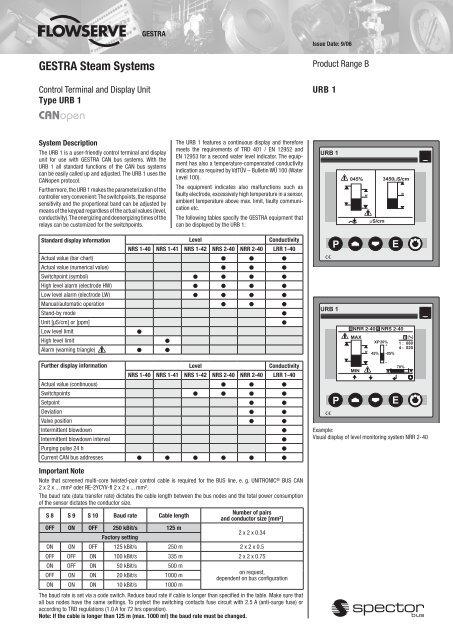
System Description<br />
The URB 1 is a user-friendly control terminal and display<br />
unit for use with <strong>GESTRA</strong> CAN bus systems. With the<br />
URB 1 all standard functions of the CAN bus systems<br />
can be easily called up and adjusted. The URB 1 uses the<br />
CANopen protocol.<br />
Furthermore, the URB 1 makes the parameterization of the<br />
controller very convenient: The switchpoints, the response<br />
sensitivity and the proportional band can be adjusted by<br />
means of the keypad regardless of the actual values (level,<br />
conductivity). The energizing and deenergizing times of the<br />
relays can be customized for the switchpoints.<br />
The URB 1 features a continuous display and therefore<br />
meets the requirements of TRD 401 / EN 12952 and<br />
EN 12953 for a second water level indicator. The equipment<br />
has also a temperature-compensated conductivity<br />
indication as required by VdTÜV – Bulletin WÜ 100 (Water<br />
Level 100).<br />
The equipment indicates also malfunctions such as<br />
faulty electrode, excessively high temperature in a sensor,<br />
ambient temperature above max. limit, faulty communication<br />
etc.<br />
The following tables specify the <strong>GESTRA</strong> equipment that<br />
can be displayed by the URB 1:<br />
Standard display information Level Conductivity<br />
NRS 1-40 NRS 1-41 NRS 1-42 NRS 2-40 NRR 2-40 LRR 1-40<br />
Actual value (bar chart) ● ● ●<br />
Actual value (numerical value) ● ● ●<br />
Switchpoint (symbol) ● ● ● ●<br />
High level alarm (electrode HW) ● ● ● ●<br />
Low level alarm (electrode LW) ● ● ● ●<br />
Manual/automatic operation ● ● ●<br />
Stand-by mode<br />
●<br />
Unit [µS/cm] or [ppm]<br />
●<br />
Low level limit<br />
●<br />
High level limit<br />
●<br />
Alarm (warning triangle) ● ●<br />
Further display information Level Conductivity<br />
NRS 1-40 NRS 1-41 NRS 1-42 NRS 2-40 NRR 2-40 LRR 1-40<br />
Actual value (continuous) ● ● ●<br />
Switchpoints ● ● ● ●<br />
Setpoint ● ●<br />
Deviation ● ●<br />
Valve position ● ●<br />
Intermittent blowdown<br />
●<br />
Intermittent blowdown interval<br />
●<br />
Purging pulse 24 h<br />
●<br />
Current CAN bus addresses ● ● ● ● ● ●<br />
Example:<br />
Visual display of level monitoring system NRR 2-40<br />
Important Note<br />
Note that screened multi-core twisted-pair control cable is required for the BUS line, e. g. UNITRONIC ® BUS CAN<br />
2 x 2 x ... mm 2 oder RE-2YCYV-fl 2 x 2 x ... mm 2 .<br />
The baud rate (data transfer rate) dictates the cable length between the bus nodes and the total power consumption<br />
of the sensor dictates the conductor size.<br />
S 8 S 9 S 10 Baud rate Cable length<br />
Number of pairs<br />
and conductor size [mm 2 ]<br />
OFF ON OFF 250 kBit/s 125 m<br />
Factory setting<br />
2 x 2 x 0.34<br />
ON ON OFF 125 kBit/s 250 m 2 x 2 x 0.5<br />
OFF OFF ON 100 kBit/s 335 m 2 x 2 x 0.75<br />
ON OFF ON 50 kBit/s 500 m<br />
OFF ON ON 20 kBit/s 1000 m<br />
ON ON ON 10 kBit/s 1000 m<br />
on request,<br />
dependent on bus configuration<br />
The baud rate is set via a code switch. Reduce baud rate if cable is longer than specified in the table. Make sure that<br />
all bus nodes have the same settings. To protect the switching contacts fuse circuit with 2.5 A (anti-surge fuse) or<br />
according to TRD regulations (1.0 A for 72 hrs operation).<br />
Note: If the cable is longer than 125 m (max. 1000 m!) the baud rate must be changed.
Control Terminal and Display Unit<br />
Type URB 1<br />
Dimensions<br />
92 +0,8<br />
Function<br />
The URB 1 communicates with other <strong>GESTRA</strong> systems<br />
via a CAN bus to DIN ISO 11898 using CANopen protocol.<br />
Design<br />
URB 1<br />
Case according to DIN ISO 43700 for panel mounting.<br />
The terminals are accessible from the back.<br />
Installation in panel cut-out by means of fixing clips<br />
supplied with the equipment.<br />
Dimensions of panel cut-out:<br />
92 +0.8 mm x 92 +0.8 mm.<br />
CAN Bus<br />
All level and temperature switches, controllers and electrodes<br />
are interconnected by means of a CAN bus. The<br />
data exchange is effected by means of a CAN bus according<br />
to DIN ISO 11898 using the CANopen protocol. Every<br />
item of equipment features an electronic address (Node<br />
ID). The four-core bus cable serves as power supply and<br />
data highway for high-speed data exchange.<br />
URB 1 is configured at our works and ready for service<br />
with other <strong>GESTRA</strong> components.<br />
URB 1 can be used straight away without having to set<br />
the Node ID.<br />
Technical Data<br />
Type approval no.<br />
TÜV · WÜL · 02-007<br />
BAF-MUC 0205 103881 003<br />
Data exchange<br />
CAN bus to DIN ISO11898<br />
CANopen protocol<br />
Indicators and adjustors<br />
1 illuminated display,<br />
resolution: 128 x 64 pixels<br />
5 push buttons<br />
Supply voltage<br />
18 V – 36 V DC<br />
Protection<br />
Front panel: IP 54 to DIN EN 60529<br />
Back: IP 00 to DIN EN 60529<br />
Admissible ambient temperature<br />
0 °C – 55°C<br />
Case material<br />
Front face: Aluminium with polyester membrane<br />
Back: Noryl GFN 2 SE 1, glass-fibre reinforced<br />
Weight<br />
Approx. 0.3 kg<br />
Wiring Diagram<br />
Bediengerät Control terminal<br />
URB 1<br />
- CL<br />
C L<br />
<br />
Terminating Abschlußwiderstand resistor 120 120 Ohm, Ω<br />
Paired Leitung cable paarig verseilt<br />
Level Niveauschalter switch<br />
NRS .…<br />
. .<br />
C H<br />
95<br />
S<br />
24V DC<br />
CAN - Bus<br />
URB 1<br />
_<br />
Conductivity Leitfähigkeitsregler<br />
controller LRR 1-40LRR 1-40<br />
1 2 3 4 5<br />
C L S C H +<br />
Conductivity Leitfähigkeitssonde<br />
electrode LRG 16-40 LRG 16-40<br />
Sensor Geber<br />
NRG ... …<br />
S CH<br />
+ ZEP CEP - CL<br />
S CH<br />
+ - CL<br />
S CH<br />
+ - CL<br />
S CH<br />
+ - CL<br />
S CH<br />
+<br />
95<br />
Code switch<br />
ON<br />
1 2 3<br />
92 +0,8<br />
BUS CAN 2 x 2 x...<br />
BUS CAN 2 x 2 x...<br />
63<br />
Order and Enquiry Specification<br />
<strong>GESTRA</strong> Control terminal and display unit type URB 1<br />
CANopen.<br />
Supply in accordance with our general terms<br />
of business.<br />
<br />
Supply Spannungsversorgung<br />
voltage<br />
Terminating Abschlußwiderstand resistor<br />
120 ΩOhm<br />
CAN data CAN-Datenleitung<br />
line<br />
Abschlußwiderstand<br />
Terminating resistor<br />
120 Ohm Ω<br />
<br />
<strong>GESTRA</strong> AG<br />
P. O. Box 10 54 60, D-28054 Bremen<br />
Münchener Str. 77, D-28215 Bremen<br />
Telephone +49 (0) 421 35 03 - 0, Fax +49 (0) 421 35 03-393<br />
E-Mail gestra.ag@flowserve.com, Internet www.gestra.de<br />
810374-05/906cm · 1998 <strong>GESTRA</strong> AG · Bremen · Printed in Germany