Railway Electrification - The Railways Archive
Railway Electrification - The Railways Archive
Railway Electrification - The Railways Archive

Create successful ePaper yourself
Turn your PDF publications into a flip-book with our unique Google optimized e-Paper software.
RAILWAY ELECTRIFICATION<br />
25 kV a.c. DESIGN ON BRITISH RAILWAYS<br />
INTRODUCTION<br />
Experience of design, installation and operationof electric traction on the<br />
railway network in Britain started over eighty years ago with d.c. conductor<br />
rail systems on suburban lines. At that time Great Britain was the first country<br />
in the world to be confronted with the problem of very dense traffic in its<br />
large towns, resulting in the need to increase the capacity of the existing<br />
railways.<br />
After a comprehensive review, in 1956 British <strong>Railway</strong>s decided to adopt a<br />
high voltage 50 Hz single-phase overhead line system for all future major<br />
electrification projects.<br />
Equipment designs and practices adopted for 25 kV 50 Hz electrification on<br />
the BR system are the result of a continuous pattern of development since<br />
1956. This development has allowed modifications to be made in the light of<br />
operating experience and advantage to be taken of technological innovations.<br />
Great stress is laid upon safety, not only for the public but also for staff<br />
operating the system and for others working on or about the electrified<br />
railway or on any other equipment located near to the electrified railway.<br />
<strong>The</strong> dense traffic patterns on the BR network, with mixed types of trains, call<br />
for an exceptionally high level of reliability in the traction supply system,<br />
to be achieved as economically as possible in first cost and in ongoing maintenance<br />
costs.<br />
<strong>The</strong> power for the 25 kV traction system is obtained from the national<br />
electricity supply network. BR does not itself own or operate any generating<br />
plant or high voltage transmission system for the purpose of supplying its<br />
25 kV traction network.<br />
1. POWER SYSTEM DESIGN<br />
1 .l Power System Study<br />
<strong>The</strong> complete power system study for electrification comprises two<br />
closely related studies - the "<strong>Railway</strong> <strong>Electrification</strong> System Design"<br />
and the "High Voltage Transmission System Study."
<strong>The</strong> railway electrification system design encompasses many aspects<br />
of the engineering and operational detail and the prime objective is to<br />
produce a 25 kV system design commensurate with the railway<br />
commercial service operating standards required and the availability of<br />
suitable electricity supplies.<br />
<strong>The</strong> high voltage transmission system study is an essential part of the<br />
programme since it must be shown that the main electrical supply system<br />
of the electricity supply authority is not unduly disturbed by the railway<br />
loads and that other consumers do not find cause to complain. Also it<br />
must be shown that sufficient power is available to obtain satisfactory<br />
operation of the railway under normal power system operation and<br />
under conditions of one worst case outage at any supply point<br />
<strong>The</strong> parameters of design typical for the interface with the high voltage<br />
transmission system at the point of common connection with the closest<br />
non-railway consumer are:-<br />
(i)<br />
System Voltage Fluctuation<br />
<strong>The</strong> voltage changes presented by the traction load to the point<br />
of common connection:.<br />
(a) <strong>The</strong> voltage change caused by load changes with a cyclic<br />
variation of greater than two hours is limited to no more<br />
than 3%.<br />
(b) <strong>The</strong> voltage change caused by load changes with cyclic<br />
variations of less than two hours but greater than two<br />
minutes is limited to a step of l%% followed by a ramp<br />
of l%% over two seconds.<br />
(ii)<br />
(iii)<br />
Limits of Unbalanee<br />
<strong>The</strong> limits used are those given in IEC standard 34-1. (Original<br />
Edition).<br />
<strong>The</strong>se state that the limit of negative phasesequence voltage<br />
that can be applied to induction motor terminals is 2% and that<br />
a.c. generators must be capable of operating when the circuit<br />
supplied absorbs a negative phase-sequence current of not more<br />
than 5% of the positive phase-sequence component.<br />
Limits of Harmonic Distortion<br />
<strong>The</strong> standard normally applied is that the maximum value of<br />
voltage distortion due to any harmonic must not exceed 1% and
the total RMS harmonic distortion must not exceed 3%.<br />
1.2 Power Supply System Capacity<br />
In order that the short-circuit capacity of the supply system is sufficiently<br />
high for it to absorb the phase unbalance currents and harmonics<br />
produced by the single-phase traction loads without exceeding the<br />
limiting values of voltage variation, it is normally necessary to make<br />
the connections to the supply authorities' networks at 132 kV. Nevertheless<br />
the single-phase transformers are connected to different phase pairs<br />
of the 132 kV system at the various supply points along the railway<br />
so as to provide the 132 kV system with a load that is balanced as far<br />
as practicable over the three phases when the traction load is at its<br />
highest.<br />
<strong>The</strong> specification for single-phase transformers stipulates an impedance<br />
value to limit the maximum fault current on the 25 kV system to a level<br />
which will avoid damage to signalling circuits and limit interference with<br />
adjacent electrical circuits and track circuits. For the British <strong>Railway</strong>s<br />
network the maximum fault current seen on the 25 kV system is<br />
normally 6 kA.<br />
1.3 Incoming Supply Arrangement<br />
<strong>The</strong> security of the incoming supply is of paramount importance to the<br />
reliability of the traction distribution system and normally the incoming<br />
feeder circuits from the 132 kV supply network to the 25 kV feeder<br />
station are duplicated at each supply point. Both incoming circuits are<br />
capable individually of carrying the total load at the incoming supply<br />
point for normal traffic operating conditions.<br />
Where practicable the HV feeders from the supply system to the 1321<br />
25 kV transformers are derived from a source which has itself a level of<br />
security at least equivalent to that afforded by the provision of independent,<br />
duplicate, fully rated, incoming feeders to the 25 kV railway<br />
distribution system. Such levels of security at the supply point may be<br />
provided by an HV busbar, sectionalised by a circuit breaker, with<br />
each section of busbar being fed via an independent circuit from an<br />
independent part of the HV network or by a duplicate HV busbar with<br />
the two busbars being similarly independently fed, such that failure of<br />
supplies to one section of the busbar does not interrupt supplies to the<br />
other. In such a case the two "railway" feeders would be connected<br />
one on eakh section of the HV busbar but may be "banked" with 132/
KEY.<br />
+Circuit<br />
Breaker<br />
.<br />
To 25kV <strong>Railway</strong><br />
Feeder Station<br />
FIGURE l<br />
FIGURE 2
33 kV or 132111 kV transformers feeding local distribution networks<br />
or other consumers to economise on 132 kV switchgear, the "bank"<br />
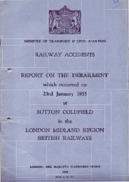
being controlled by a single 132 kV circuit breaker (See Figure 1 -<br />
Diagram of a typical 132 kV supply arrangement).<br />
<strong>The</strong> loss of both 25 kV supplies to a feeder station,which may.statistically,<br />
occur only once within the life of the equipment, can be catered<br />
for by transferring the load on each of theincoming 25 kV feeders to<br />
the nearer 25 kV incoming feeder at the adjacent feeder stations. Such a<br />
transfer would give rise to some loss of train performance in the affected<br />
section since the voltage drop from the feeder station to the pantographs<br />
would be higher than under normal feeding conditions due to the increased<br />
loadings and the increased 25 kV feeding distances. This loss of<br />
performance would be reflected in slightly longer running times for trains<br />
passing through the section, but any such lost time should be recovered<br />
in the succeeding normally--fed sections with the result that overall<br />
journey times are unaffected.<br />
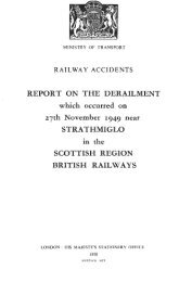
<strong>The</strong> power supply points for the 25 kV system are required at intervals<br />
of between 40 and 60 kilometres and under normal feeding arrangements<br />
each one feeds to the mid-points between itself and the adjacent supply<br />
points. Further electrical sectioning and paralleling of the overhead line<br />
track equipment is provided by track sectioning cabins. A typical<br />
arrangement is shown in Figure 2.<br />
For the supplies from the 132 kV system, British <strong>Railway</strong>s has standardised<br />
on two sizes of transformer:.<br />
10 MVA Oil immersed, naturally cooled which with the addition of oil<br />
circulating pumps and forced air cooling have a rating of 14 MVA. This<br />
design of transformer, which is used mainly on suburban electrified<br />
lines. has a fixed ratio of 132125 kV.<br />
18 MVA Oil immersed, naturally cooled which with the addition of oil<br />
circulating pumps and forced air cooling have a rating of 26.5 MVA. This<br />
design of transformer has a variable ratioof 132125 kV minus 0% plus<br />
12W% in 2%% steps. On-load tap changing equipment is not provided,<br />
the transformer ratio adjustment being achieved by offcircuit selectors.<br />
Experience has shown that once adjusted to give the most favourable<br />
operating no-load voltage, as determined by the characteristics of the<br />
incoming supply voltage, the tapping position is unlikely to be changed.
1.4 Earthing<br />
<strong>The</strong> earthing of British <strong>Railway</strong>s traction equipment conforms to the<br />
recommendations of British Standard Code of Practice C.P. 1013, 1965,<br />
the Electricity Council's Engineering Recommendations S511 and the<br />
Institution of Electrical Engineers' Regulations. <strong>The</strong> key parameter<br />
is to hold the potential of exposed metal to a value not exceeding 25<br />
volts under normal operating conditions or 430 volts under traction<br />
system fault conditions, measured to the general mass of the earth.<br />
It is normally not necessary to use driven earth rods, as the foundations<br />
of the overhead line structures connected in parallel by means of the<br />
traction return current rail of the track, keep the earth resistance to an<br />
acceptable level. Each overhead line supporting structure is generally<br />
directly bonded to the traction return rail of the adjacent track by<br />
stranded aluminium conductor sheathed with PVC. As the structure<br />
foundations vary in depth from two to three metres, they are little<br />
affected by changing weather conditions; the resistance of a single<br />
footing does not exceed 20 ohms and is normally much less. When<br />
interconnected they provide a very satisfactory distributed earthing<br />
system having an overall resistance to earth of 1 ohm or less.<br />
1.5 Suppression of Interference<br />
<strong>Railway</strong> telecommunications and signal circuits parallel the electric railway<br />
throughout its length at close proximity and are therefore exposed<br />
Feeder Station.<br />
l<br />
l<br />
U<br />
=<br />
25kV m Return Cvrrenl<br />
EuII@ar. ' r Busbar.<br />
KEY.<br />
BIT<br />
I.O.S.<br />
Booster Transformer.<br />
Insulated Overlap Span.<br />
Return current Busbar<br />
10 Rail Bonds.<br />
Return conductor.<br />
Overhead Contact<br />
wire.<br />
Rail.<br />
FIGURE 3
to electrical interference from the overhead line traction conductors.<br />
British <strong>Railway</strong>s conform to the Directives of the CClTT and, in the<br />
design of the fixed traction equipment, booster transformers and return<br />
conductors are used to provide as much suppression as is practicable<br />
at source. In addition the Telecommunications Engineer takes protective<br />
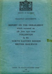
precautions on the communications systems. <strong>The</strong> normal maximum<br />
spacing of the booster transformers is 3 kilometres. (See Figure<br />
3 - Diagram of booster transformer system).<br />
<strong>The</strong> return conductors are carried on but insulated from the overhead<br />
line equipment supporting structures. <strong>The</strong> booster transformers, which<br />
have a 111 ratio, force a current through the return conductor equal and<br />
opposite to the current in the associated catenarylcontact wires. Nevertheless<br />
the spacing between the two conductors constitutes an inducing<br />
loop which will cause induced current in adjacent conductors and in<br />
the traction return rails. This secondary induced rail current, the value<br />
of which will be dependent upon rail impedance and rail to earth impedance,<br />
will itself have an inducing effect upon adjacent conductors.<br />
For some of these adjacent conductors the inducing effect of the 'loop'<br />
will be dominant, and for others the inducing effect of the rail current,<br />
dependent upon the relative physical dispositions of the conductors<br />
concerned.<br />
Calculation of induced voltages is an extremely complex operation and<br />
computer programs have been developed to assist in this work.<br />
Booster transformers are of simple robust construction and have proved<br />
to be very reliable in service. Specifications call for the magnetising<br />
currents to be limited, since these represent an imbalance between the<br />
primary and secondary currents, not only at the fundamental frequency,<br />
but at higher frequencies. Saturation levels for the cores need to be<br />
kept well above the maximum peak load current levels since they also<br />
product a primarylsecondary imbalance and, for currents above saturation<br />
level, will affect the wave shape of the secondary current. Some<br />
saturation does occur under fault conditions, particularly for faults<br />
near to the incoming supply points.<br />
2. POWER SUPPLY TARIFF ARRANGEMENTS<br />
Electricity for traction on British <strong>Railway</strong>s is purchased from two supply<br />
authorities, the Central Electricity Generating Board (CEGB) covering England<br />
and Wales and the South of Scotland Electricity Board (SSEB) in Scotland.
<strong>The</strong> CEGB and SSEB tariffs for traction supplies differ in detail, but have the<br />
following common principles:-<br />
(i)<br />
Service Charge<br />
At each supply point the supply authority provides the HV switchgear,<br />
the railway supply transformers and the associated metering and protection<br />
equipment. <strong>The</strong> capital cost of this equipment is commuted to an<br />
annual service charge.<br />
(ii)<br />
Capacity Charges<br />
To cover the cost of providing capacity in the generating and HV transmission<br />
system the two supply authorities make capacity charges which<br />
are related to the total railway demand on the supply authority system<br />
at the time(s) of supply system maximum demandk).<br />
(iii) Running Charges<br />
<strong>The</strong> cost of energy is related to the actual cost of base fuels (coal, oil or<br />
nuclear fuel). To assist the supply authority with management of the<br />
system load, an incentive to consume energy at times of system minimum<br />
demand is given by supply authorities through cheaper off-peak<br />
rates.<br />
<strong>The</strong> overall cost of electricity for traction on British <strong>Railway</strong>s is made up<br />
approximately of 2% Service Charge, 25% Capacity Charges and 73% Energy<br />
Charges.<br />
3. 25 kV DISTRIBUTION EQUIPMENT<br />
<strong>The</strong> major item of distribution equipment is the 25 kV Switchgear and in<br />
the interests of economy in first cost, ease of installation and minimisation<br />
of maintenance, switchgear incorporating vacuum interrupters<br />
is now standard on British <strong>Railway</strong>s. <strong>The</strong> vacuum interrupter shows<br />
marked improvements over the bulknil type circuit breakers previously<br />
used, not least in removing entirely the risk of fires and explosions inherent<br />
in the presence of quantities of oil. <strong>The</strong> small contact travel and<br />
light weight of moving pans means also that simple, very lightly stressed,<br />
operating mechanisms can be used with consequent savings in auxiliary<br />
power supplies for operating purposes.
FIGURE 4 FIGURE 5<br />
FIGURE 6<br />
9
<strong>The</strong> interrupters themselves are virtually maintenance free, the only<br />
routine attention being the cleaning of insulator surfaces and a periodic<br />
test for loss of vacuum. Since busbar insulation needs cleaning at the<br />
same period as the interrupter insulation a common outage may be<br />
utilised for such cleaning, for the vacuum loss test and for testing the<br />
integrity of conductor joints. It is not necessary to isolate circuit and<br />
busbar components independently and busbar isolating facilities have<br />
been dispensed with on incoming and outgoing circuit units. External<br />
circuit disconnecton are used to isolate the switchgear from any incoming<br />
feeder circuits and from the overhead line equipment, thus<br />
obviating the requirement for integral circuit disconnector facilities.<br />
Provision is made to enable a faulty interrupter assembly, complete with<br />
its operating mechanism, to be removed and replaced by a spare unit,<br />
pre-adjusted in the maintenance workshops.<br />
At feeder stations and at mid-point track sectioning cabins, where neutral<br />
sections are provided in the overhead catenarvlcontact system, bursection<br />
circuit breakers are provided in the 25 kV switchgear. <strong>The</strong>se<br />
circuit breakers have isolatinglearthing facilities on each side and are<br />
provided with metal barrien with through bushings. <strong>The</strong>se facilities<br />
enable either half of the switchboard to be shut down and the appropriate<br />
section of busbar to be earthed with the other half still in full working<br />
condition. Maintenance outages can then be arranged with only a<br />
minimal amount of emergency feeding even at a feeder station. Similar<br />
facilities are not considered necessary at intermediate track sectioning<br />
cabins since the external overhead line disconnecton can be arranged<br />
to by-pass the switching station when an outage is required for maintenance<br />
purposes.<br />
I<br />
Connections from the switchgear to the overhead catenary system or<br />
l<br />
from the incoming supply transformers are made in bare conductors,<br />
through-roof bushings being utilised to take these connections from the 1<br />
inside to the outside of the switchgear enclosure. <strong>The</strong> bushings them-<br />
1<br />
selves provide a convenient location for current transformers for pro- 1<br />
tection purposes, the protection relays being mounted on the front<br />
panels of the circuit breaker equipment.<br />
<strong>The</strong> enclosure for the switchgear is extremely simple, a factory prefabricated<br />
modular steel construction being used. By extending the<br />
enclosure slightly beyond the circuit breaker equipment, space is provided<br />
for ancillary equipment such as tripping batteries, supervisory<br />
control equipment cubicles, telephones and the like, enabling inter-
connecting wires to be run directly without recourse to the auxiliary<br />
cabling necessitated by separate buildings. <strong>The</strong> enclosure requires only a<br />
simple slab concrete base that can be laid by the same train as is used<br />
for concreting the foundations for the overhead equipment structures.<br />
All 25 kV switchgear is, under normal operating conditions, remotely<br />
controlled from an electrical control room but provision is made, by<br />
means of control changeover switches and local control switches, to<br />
enable the circuit breakers to be operated at the switchgear. Where<br />
motor-wound spring closing mechanisms are used, facilities are also<br />
provided for manual charging and release of the springs and for both<br />
springclosed and solenoidclosed circuit breakers, direct mechanical<br />
trip buttons are fined.<br />
Because the mechanisms have a very low loading, closing coils, closing<br />
releases and trip coils have a low auxiliary power demand which can be<br />
catered for by simple sealed cell batteries. Spring mechanisms are<br />
arranged to recharge automatically after a closing operation, thus ensuring<br />
that a further closure can be made even if the auxiliary supply<br />
for the spring winding motor is lost. Provision is made to ensure that<br />
the supervisory control equipment remains operative in the event of the<br />
loss of auxiliary power supplies to enable essential switching operations<br />
to be carried out under remote control.<br />
Figures 4 and 5 illustrate respectively the operating corridor and the<br />
25 kV chamber of the 25 kV switchgear and figure 6 shows a vacuum<br />
circuit breaker spring operating mechanism with cover removed.<br />
3.2 Protection Equipment<br />
<strong>The</strong> protective scheme provided for track feeder circuit breakers is a<br />
slightly modified version of the static distance-measuring relay scheme<br />
which has been used for a number of years to provide highspeed protection<br />
for high voltage transmission systems throughout the world. <strong>The</strong><br />
advantage of this relay is that it can maintain very fast operating speeds<br />
and high accuracy of measurement over a very wide range of system<br />
conditions. This is of importance on a multi-track railway where it is<br />
essential not only to give rapid fault clearance but to prevent the<br />
disconnection of supplies to healthy sections of overhead line equipment.
Basically there is a three-zone scheme of distance protection, with Zone<br />
l providing instantaneous protection for about 80435% of the protected<br />
section, and Zones 2 and 3 providing timedelayed protection for faults<br />
in the end of the protected section not covered by Zone 1 and back-up<br />
protection for faults in adjacent sections. Static timing circuits are<br />
incorporated to provide the necessary time delays.<br />
Use of static protection equipment in conjunction with the vacuum<br />
circuit breaker has reduced the total Zone 1 fault clearance time to<br />
about 90 milli-seconds, compared with 200 milli-seconds with electromagnetic<br />
protection and oil circuit breakers, with consequential reduction<br />
in the stresses to which the overhead equipment is subjected<br />
under fault conditions.<br />
Protection against very high impedance faults or sustained heavy overloads<br />
on track feeder circuits iqprovided by thermal overcurrent relays.<br />
Bus-section units are equipped with overcurrent protection arranged to<br />
give an instantaneous trip if closed onto a fault: following a successful<br />
closure, the overcurrent protection may then be time delayed to act as a<br />
back-up for the track feeder circuits on the same switchboard or, if<br />
back-up can be provided adequately by the track feeders at adjacent<br />
switching stations, rendered inoperative to avoid maldiscrimination with<br />
the track feeder protection. At mid-point track sectioning cabins, relays<br />
are provided to sense the voltage on the two sections of busbar and<br />
allow closure of the bur-section circuit breaker only when one of the<br />
two sections is not energised.<br />
<strong>The</strong> primary protection scheme on incoming supply circuit breakerk)<br />
at the 25 kV Feeder Stations is co-ordinated with the protection equipment,<br />
normally consisting of a form of circulating current or balanced<br />
earth fault protection, fitted to the high voltage circuit breakerk) controlling<br />
the supply transformer(s) to cover faults on the transformer(s)<br />
or on the high voltage or 25 kV connections to the transformer(s).<br />
Additionally, an inverse time definite minimum time overcurrent relay<br />
is provided to cover 25 kV busbar faults, or sustained high overcurrents,<br />
and to afford back-up should an outgoing track feeder circuit breaker<br />
fail to clear a fault. <strong>The</strong> trip circuit is monitored continuously to draw<br />
attention to any failure of the trip supply or to any break in the tripping<br />
circuit.
3.3 Supervisory Control System<br />
With the advent of microprocessor, solidstate supervisory systems the<br />
tendency on British <strong>Railway</strong>s has been for electrical control rooms to<br />
extend the electrified area supervised and a number of control rooms<br />
supervise 1500 single track kilometres of electrified line and are capable<br />
of extensions to control at least 3000 single-track kilometres.<br />
<strong>The</strong> solidstate equipment operates in a continuous scanning mode in<br />
which data is continually being transmitted from the control centre to<br />
the out-stations and vice versa. Timedivision multiplex principles are<br />
used whereby all stations in the system are scanned in turn, the scanning<br />
mechanism pausing on each station for a short period of a few milliseconds,<br />
so that the condition at that switching station can be transmitted<br />
to the control centre. If the state of any equipment in that<br />
switching station has altered since the previous scan, all circuit breakers<br />
and alarm functions are interrogated and the complete information<br />
pertaining to the station transmitted to the control centre and indicated<br />
on a mimic diagram from which all circuit breakers can be controlled.<br />
<strong>The</strong> system ensures that the control operator's attention is drawn very<br />
rapidly to the operation of any item of equipment not initiated at the<br />
control room or to the occurrence of an alarm condition. <strong>The</strong> computerbased<br />
equipment5 enable all operating events to be automatically logged<br />
and recorded on a paper printout.<br />
3.4 Distribution Equipment Maintenance<br />
In developing distribution equipment for traction networks, British<br />
<strong>Railway</strong>s' principal objective after ensuring that the prime requirements<br />
of safety and reliability have been achieved, is to reduce maintenance<br />
and outages of equipment to a minimum. That this has successfully<br />
been achieved with the current ranges of equipment adopted for British<br />
<strong>Railway</strong>s' projects. where the switching stations have' been designed<br />
to exploit fully the capabilities of vacuum interrupters, is borne out by<br />
experience with the Weaver Junction - Glasgow installations, brought<br />
into full commercial service in 1974.<br />
All maintenance o f the distribution equipment, including supervisory<br />
control, protection and standby signalling supplies on the 450 singletrack<br />
kilometre section in Scotland is carried out by a total of four<br />
staff.
A comparison between the maintenance attention given to switchgear<br />
incorporating vacuum interrupters and that to switchgear incorporating<br />
oil circuit breakers shows that each oil circuit breaker equipment has<br />
received three times as many man-hours attention as the vacuum circuit<br />
breaker equivalent. <strong>The</strong> oil circuit breaker figures include the time<br />
spent in the switching stations for changing oil, but exclude any time<br />
spent in the handling or treatment of oil outside the switching stations.<br />
It is pertinent to note that, to date, the attention given to switchgear<br />
incorporating vacuum interrupters has consisted almost entirely of<br />
periodic inspections, carried out by staff during visits to the switching<br />
stations for other reasons. <strong>The</strong> actual amount of work required following<br />
these inspections has been negligible.<br />
4. OVERHEAD LINE EQUIPMENT& ELECTRICAL CLEARANCES<br />
4.1 Overhead Line Equipment<br />
4.1.1 Design<br />
<strong>The</strong> cost of overhead line equipment and provision of electrical<br />
clearance on electrification projects forms a significant pan of<br />
the total investment and therefore considerable effort has been<br />
devoted to achieving the maximum economy in the design of<br />
the British <strong>Railway</strong>s Mark Ill ranges of overhead line equipment.<br />
Cost-effective techniques were applied throughout all stages of<br />
design of the equipment, with account also taken of the advantages<br />
of simplifying the assembly of components to achieve<br />
improved productivity of installation work. In addition, account<br />
was taken at the design stage of the financial benefits of reducing<br />
the total range of components required. <strong>The</strong> prime objective<br />
of the design was to produce an equipment suitable for high<br />
speeds with high reliability and requiring a minimum of maintenance,<br />
all aspects especially essential for lines with high traffic<br />
density and limited opportunity of possessions for maintenance<br />
work.<br />
<strong>The</strong> Mark lllB range of equipment provides good current<br />
collection for 200 kmlh operation. Consequently, in respect of<br />
current collection capability, it is not considered necessary to<br />
depart from a simple, two-conductor system unless there is a
future requirement for operating speeds significantly above<br />
200 kmlh, when the conductor configuration may be dictated<br />
by current-carryingcapability, rather than the standard of<br />
current collection.<br />
Particular features of Mark Ill6 overhead equipment are as<br />
follows:-<br />
Nominal continuous current rating 600 A.<br />
Copper-equivalent cross-sectional area:-<br />
with new contact wire = 150sq mm<br />
with contact wire worn 33.3% = llOsqmm<br />
Main conductors:.<br />
catenary<br />
contact wire<br />
- 7/3.95 mm with 5 wires Aluminium, 2 wires<br />
Aluminium-coated steel on opposite sides of<br />
the outer layer. 11 kN tension.<br />
- 107 sq mm solid, grooved, hard-drawn copper.<br />
11 kN tension.<br />
Apart from the contact wire and fittings connected directly to<br />
it, almost all the overhead equipment components are steel or<br />
malleable cast-iron galvanised, or of aluminium or stainless<br />
steel. <strong>The</strong>se minimise the use of comparatively expensive copper<br />
components.<br />
Except in sidings, where fixed termination of conductors is<br />
often employed, the equipment is automatically tensioned,<br />
usually by weights and pulleys, in order to maintain constant<br />
tension within +l%% in the catenary and contact wire over a<br />
temperature range of 56'~. For this temperature range, the<br />
maximum tension length into which the equipment can be<br />
divided in just under 2 km.<br />
Except inbareas of high wind, where lower figures apply, the<br />
maximum span length is 73 m on straight track, but this can<br />
be extended to 75 m should a subterranean obstruction be<br />
discovered during excavation of the mast foundations on site.
Span length is governed mainly by the tensions in the conductors<br />
and blow-off due to wind, related to the maximum<br />
permissible deviation of the contact wire of 400 mm from the<br />
centre of the pantograph, which allows for sway of the locomotive<br />
and tolerances on adjustment of the track and overhead<br />
equipment.<br />
<strong>The</strong> majority of insulators employed are of the solid-core porcelain<br />
type, or, in main conductors, the porcelain disc type.<br />
However, the following insulators based on glass-fibre rods are<br />
of interest:-<br />
(a) Silicone rubber-covered glass-fibre rods for in-line insulation<br />
where their small diameter is useful in providing greater<br />
clearance at overlaps from passing pantographs, and their<br />
light weight is also useful in avoiding excessive sag of the<br />
catenary.<br />
(b) A larger diameter glass-fibre rod with PTFE or silicone<br />
rubber covering, used as an insulated resilient support for<br />
the overhead equipment beneath overbridges or in tunnels,<br />
allowing the use of reduced electrical clearances due to its<br />
consistent and predictable dynamic performance (See Figure<br />
7).<br />
FIGURE 7<br />
16
(C) Insulators with ceramic beads threaded onto a glass-fibre rod<br />
which have inner surfaces vacuum-impregnated with silicone<br />
rubber. This type of insulator is designed so that pantographs<br />
can run in direct contact with the ceramic beads and, because<br />
of its low weight and small diameter, its dynamic performance<br />
is similar to that of the length of contact wire<br />
which it replaces. Ceramic bead insulators are used for the<br />
insulating members of high speed section insulators and<br />
neutral sections. In the latter application, two insulators<br />
are inserted into the contact wire equidistant about a<br />
supporting structure, the short section of wire between<br />
them being earthed and the total along-track length of nonenergised<br />
contact wire being 4.5m.<br />
Apart from a few special varieties, structures comprise masts<br />
for cantilevers, each supporting one equipment on single or<br />
double track, and masts for multi-track headspans, where<br />
two are connected by wires spanning the tracks to support<br />
the overhead equipments. <strong>The</strong>y are of plain Universal<br />
Column (H section) galvanised steel in a range of 6 sizes<br />
between 152 X 152 mm X 23 kglm and 356 X 368 mm X<br />
129 kglm. <strong>The</strong> three smaller sizes are used for cantilever<br />
masts and the three larger sizes, either singly or in braced<br />
pairs, depending upon the number of overhead equipments<br />
to be supported and number of tracks to be spanned, for<br />
headspans.<br />
Foundations are generally of the side-bearing, reinforced<br />
concrete type, incorporating a soluble core former to provide<br />
a hole into which a mast can be inserted and grouted in<br />
position.<br />
Gravity slab foundations are used on soft ground and, In<br />
hard rock, small concrete foundations are anchored in<br />
position by bars fastened into the rock.<br />
See Figure 8<br />
See Figure 9<br />
- Cantilever Type Construction<br />
- Headspan Type Construction
FIGURE 9<br />
18
4.1.2 Maintenance<br />
<strong>The</strong> pantographs on British <strong>Railway</strong>s are fitted with metallised<br />
carbon collector strips and latest wear measurements indicate<br />
that the life expectancy of the hard-drawn copper contact wire<br />
will be about 60 years, even on the high speed, high traffic<br />
density routes.<br />
<strong>The</strong>re has been a significant reduction in maintenance requirements<br />
with Mark Ill equipment compared with earlier equipment<br />
and insulator cleaning is confined to limited areas of heavy<br />
chemical/industrial pollution.<br />
Staffing for overhead line equipment maintenance is now less<br />
than one man per ten single-track kilometres.<br />
4.1.3 Installation<br />
<strong>The</strong> plans, cross-sections, Bill of Quantities and all other documentation<br />
required for installation of the overhead line equipment,<br />
representing the application of the basic designs to an<br />
actual length of railway and known as "Overhead System<br />
Design" (OSD), are produced by a specialist BR team.<br />
<strong>The</strong> cost of producing OSD documentation has been greatly<br />
reduced in recent years by computerising the calculations, production<br />
of much of the drawings and of the Bill of Quantities.<br />
<strong>The</strong> cost of the overhead line equipment itself has also been<br />
reduced by more accurate allocation of structures and foundations<br />
to suit the loadings applicable in each case, made<br />
possible by the computer.<br />
It is unlikely that significant further economy can be gained<br />
from the design of overhead line equipment, but great savings<br />
have been made and will continue to be made by careful planning<br />
of installation work, timing it so that it follows at a suitable interval<br />
behind preliminary work on the track and signalling, as a<br />
continuous, mass-production operation.<br />
<strong>The</strong> plant employed and its method of operation have been<br />
developed .over the years, so as to carry out the maximum<br />
amount of work in the course of a track occupation and also<br />
special equipment has been provided and techniques developed<br />
to permit the maximum amount of work to be carried out<br />
without possession of the track.
4.2 Electrical Clearances<br />
British <strong>Railway</strong>s' electrical clearances were originally based on the UIC<br />
recommendation and for 25 kV were 270 mm static clearance and<br />
200 mm passing clearance, requiring a total headroom above kinematic<br />
load gauge at a support point of 680 mm. In 1962, following tens and<br />
service experience, the statutory clearance requirements on BR were<br />
revised and reduced clearances of 200 mm static and 150 mm passing as<br />
shown in Figure 10 were introduced for 25 kV operation. <strong>The</strong>se reduced<br />
requirements, together with modifications to the design of the overhead<br />
equipment, meant that the minimum headroom could be reduced by<br />
175 mm and this significantly reduced the costs of obtaining electrification<br />
clearances.<br />
Research and development work had also established that where insufficient<br />
headroom is available to allow the normal catenarylcontact<br />
wire arrangement, a "twin-contact wire" arrangement where the catenary<br />
is replaced by contact wire and the two contact wires are supported<br />
side-by-side, gave good current collection even with the most restricted<br />
clearance arrangement at bridges.<br />
.......................<br />
. . . . . . . . . . . . . . . . . . . . . . . .<br />
Parring Clearance OHL Support to Structure<br />
Uplift<br />
Toleran<br />
Construction Depth Max 120 1 505<br />
Designed Contact Wire Level 1<br />
Passing Clearance Vehicle to Contact Wire Min 150<br />
Track Tolerance<br />
Kinematic Load Gauge - Normal B R Height<br />
Designed Rail Level<br />
15<br />
f<br />
4015 l<br />
t<br />
REDUCED CLEARANCES FIGURE 10
A key factor in perfecting the twin-contact wire arrangement and so<br />
reducing the headroom for 25 kV equipment, was the development<br />
of large resin-bonded glass-fibre rods with track-resistant surface<br />
covering, which provided a flexible and virtually indestructible combined<br />
insulator and support for the twin-contact wires.<br />
In 1974, design effort was concentrated on the investigation of possible<br />
further reductions in electrical clearance. <strong>The</strong> objective set was that any<br />
improved arrangement must not degrade the surge and 50 Hz voltage<br />
withstand levels achieved with the existing arrangements. <strong>The</strong>se levels<br />
were found to be governed by the electrical stress between the live<br />
end fitting on the equipment support arm and the roof of the bridge or<br />
tunnel. This fitting was re-designed to a semi-circular shape, to distribute<br />
the electrical stress more evenly, as shown in Figure 7.<br />
It has enabled the clearance above the live end fitting of the support<br />
assembly to be reduced to 95 mm static and 70 mm passing. At the same<br />
time, the passing clearance from contact wire to kinematic load gauge<br />
was reduced to 125 mm. <strong>The</strong>se "Special Reduced Clearance" arrangements,<br />
shown in Figure 11, mean that a total of only 375 mm of head-<br />
Passing Clearance OHL Support to Structure<br />
;<br />
1 g<br />
.- U<br />
..<br />
Uplift -(D<br />
Max 50 or 25<br />
V)<br />
Tolerance<br />
Construction Depth<br />
Designed Contact Wire Level 1<br />
Passing Clearance Vehicle to Contact Wire Min 125 1 I<br />
I<br />
Track Tolerance<br />
Kinematic Load Gauge -Ndrrnal B R Height<br />
Designed Rail Level<br />
SPECIAL REDUCED CLEARANCES FIGURE 11
oom is required above kinematic load gauge for 25 kV equipment.<br />
an additional 25 mm being allowed for increased uplift of the contact<br />
wire at speeds above 60 kmlh. Special reduced clearances are adopted<br />
in all cases of exceptional difficulty or expense in obtaining greater<br />
headroom.<br />
5. CONCLUSIONS<br />
This paper describes briefly the development of system and equipment design<br />
for a.c. electrification on BR since its introduction over 25 years ago. Over<br />
that period major advances have been made in the application of modern<br />
technologies to all the engineering aspects of electrification design so that<br />
costs of current schemes are now not only half of those, in real terms, of<br />
earlier schemes, but are also amongst the lowest in the world. This achievement<br />
has however not been made at the expense of design standards which<br />
necessarily remain at a very high level.