MFJ-8100K Manual
MFJ-8100K Manual
MFJ-8100K Manual

You also want an ePaper? Increase the reach of your titles
YUMPU automatically turns print PDFs into web optimized ePapers that Google loves.
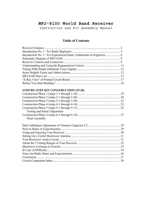
<strong>MFJ</strong>-8100 World Band Receiver<br />
Instruction and Kit Assembly <strong>Manual</strong><br />
Table of Contents<br />
Receiver Features ...................................................................................................... 2<br />
Introduction No. 1: For Radio Beginners................................................................. 3<br />
Introduction No. 1: For Experienced Hams, Enthusiasts or Engineers.................... 6<br />
Schematic Diagram of <strong>MFJ</strong>-8100 ............................................................................. 8<br />
Receiver Controls and Connectors............................................................................ 9<br />
Understanding and Using the Regeneration Control................................................. 11<br />
Tuning SSB (Single Sideband) Voice Signals .......................................................... 12<br />
Some Helpful Terms and Abbreviations................................................................... 13<br />
<strong>MFJ</strong>-8100 Parts List.................................................................................................. 15<br />
"X-Ray View" of Printed Circuit Board.................................................................... 17<br />
Before You Start Building ! ...................................................................................... 18<br />
STEP-BY-STEP KIT CONSTRUCTION (19-28)<br />
Construction Phase 1 (steps 1-1 through 1-10) ......................................................... 19<br />
Construction Phase 2 (steps 2-1 through 2-20) ......................................................... 20<br />
Construction Phase 3 (steps 3-1 through 3-20) ......................................................... 22<br />
Construction Phase 4 (steps 4-1 through 4-14) ......................................................... 23<br />
Construction Phase 5 (steps 5-1 through 5-11) ......................................................... 25<br />
Testing and Initial Adjustment<br />
Construction Phase 6 (steps 6-1 through 6-18) ......................................................... 27<br />
Final Assembly<br />
Dial Calibration Adjustment of Trimmer Capacitor C5............................................ 29<br />
Note to Hams or Experimenters................................................................................ 29<br />
Using and Enjoying Your Receiver........................................................................... 30<br />
Setting Up a Useful Shortwave Antenna................................................................... 31<br />
Your Receiver's Audio Circuit .................................................................................. 31<br />
About the 5 Tuning Ranges of Your Receiver .......................................................... 32<br />
Shortwave Listening in General ................................................................................ 33<br />
In Case of Difficulty.................................................................................................. 34<br />
Notes for Radio Hams and Experimenters................................................................ 36<br />
Conclusion................................................................................................................. 37<br />
Circuit Component Index .......................................................................................... 38
<strong>MFJ</strong>-8100 Receiver Features<br />
• Five separate tuning ranges between 3.5 and 22 MHz.<br />
• Smooth 6:1 vernier-reduction tuning dial<br />
• Sensitive FET RF amp and detector stages<br />
• Dual headphones for sharing the fun<br />
• Use economical "personal stereo" headphones or speakers<br />
• Smooth, well-engineered regeneration circuit<br />
• True choice of AM-CW-SSB reception<br />
• Excellent reception even with a few feet of wire antenna<br />
+ VERY IMPORTANT PLEASE READ:<br />
Your receiver carries <strong>MFJ</strong>'s respected No Matter What guarantee specifically to the<br />
extent that you may return the entire kit UNASSEMBLED for credit or refund. If you have<br />
never built an electronics kit before, PLEASE study this book carefully before unpacking<br />
the small parts. Once you have begun soldering parts, neither <strong>MFJ</strong> or any dealer can accept<br />
the return of the kit for any reason whatsoever.<br />
<strong>MFJ</strong>-8100 World Band Receiver<br />
Instruction and Kit Assembly <strong>Manual</strong><br />
Instruction <strong>Manual</strong> developed and designed by Dan F. Onley, K4ZRA<br />
Copyright © 1993 by <strong>MFJ</strong> Enterprises, Inc. All Rights Reserved. No part of this work<br />
may be copied or reprinted without the explicit permission of the copright owner.<br />
<strong>MFJ</strong> Enterprises, Inc.<br />
300 Industrial Park Road<br />
Starkville, MS 39759<br />
Printed in the United States of America.<br />
2
Introduction No. 1:<br />
For Radio Beginners<br />
You're about enjoy a versatile shortwave receiver which employs a circuit concept that is<br />
as classic as the 1920's but which uses modern engineering that takes advantage of the<br />
advanced capabilities of today's electronic components.<br />
This shortwave radio is designed to let you listen to a great variety of international<br />
broadcasts. You can choose from five different frequency "bands'' so that you can count<br />
on hearing SOMETHING at any hour of day or night. Also, this receiver lets you hear a<br />
generous sampling of ham radio signals (both Morse code "CW'' and voice "SSB''<br />
communications), plus many other government and commercial transmissions.<br />
Even if you have never worked with electronic parts before, you can successfully build<br />
this receiver by carefully following all the directions in this book. Step by step, we'll<br />
show you how to build it and how to enjoy it. Before you start building however, please<br />
read the notice on page 2 so that there is no misunderstanding about your rights as a<br />
valued <strong>MFJ</strong> customer.<br />
Just a Bit of History . . .<br />
The "regenerative receiver'' moved the world of radio reception and broadcasting beyond<br />
the limits of crystal sets useful only for hearing a strong local signal. For over a decade,<br />
these magical, whistling, squawking, glowing boxes were the norm for home listening as<br />
well as for the first generation of radio hams.<br />
Receiver design evolved swiftly. The "superheterodyne'' became the norm during the<br />
1930's. Regenerative receivers, often called "Gennies,'' were left to tinkerers and<br />
beginners. Even though these receivers were simple and quite sensitive, they had a<br />
number of shortcomings: instability, touchiness, difficulty in separating strong stations, a<br />
tendency to generate interference to other receivers, and a general reputation for making<br />
odd sounds that resembled everything from pigs to motorboats.<br />
However, the sheer SIMPLENESS of the regenerative circuit remained attractive to<br />
experimenters and beginners. In fact, as recently as the 1960's, one company marketed a<br />
$14 kit for building a complete transceiver using only one vacuum tube: half of the tube<br />
served as a regenerative receiver, and the other half was a low-power crystal-controlled<br />
transmitter. In addition, many thousands of engineering careers as well as ham radio<br />
licenses were launched with the building of "my first shortwave radio'' from do-it-yourself<br />
regenerative receiver kits offered by the major radio companies of several decades ago.<br />
(The fondest dream BACK THEN of most of these radio builders was to be able to afford<br />
to move up to a "superhet communications receiver.'' Their fondest memory TODAY is<br />
that very first receiver kit.)<br />
3
From the late 1970's through the '80's, as consumer electronics and new ham radio<br />
equipment became more sophisticated so very rapidly, interest declined not only in<br />
regenerative receivers, but also in kit-building and even in shortwave radio listening. One<br />
or two generations of Americans simply missed out on the thrill and satisfaction of<br />
building and understanding a simple radio set which could receive signals from anywhere<br />
in the world.<br />
Back to Today . . . and the Future!<br />
Your <strong>MFJ</strong>-8100 is a much better receiver than the "classic'' radio sets which attracted<br />
several generations of Americans to the excitement of radio and electronics. In fact, its<br />
basic performance is superior to many of the simplest superhet receivers which were<br />
considered such a great step beyond one's first regenerative set.<br />
The reason why this receiver works so well is because there is much more precision in<br />
today's engineering designs and the manufacturing of electronic parts. We looked<br />
carefully at the practical problems associated with yesteryear's technology, and we used<br />
TODAY'S know-how and components to solve the problems.<br />
A Simplified Explanation of How It Works<br />
When you're ready, please explore the technical explanation of your receiver in<br />
"Introduction No. 2.'' In the meantime, you can peek at the schematic diagram and picture<br />
the receiver in three basic sections:<br />
A. Detector-Oscillator (Q1,Q2)<br />
B. RF amplifier (Q3)<br />
C. Audio amplifier (IC1)<br />
To put it very simply, a detector converts radio energy from an antenna into audio energy,<br />
i.e., a sound which you can hear. A detector can be as simple as a crystal diode, which is<br />
the heart of the simple "crystal radio.'' If you've ever heard unwanted radio signals on a<br />
stereo, telephone, PA system or intercom, you can assume that some part of those devices<br />
has acted as a detector to convert a nearby CB, taxi or broadcast signal into intelligible<br />
sound. (This process of detection is also referred to as demodulation.)<br />
In the following explanation, the words regeneration, feedback and oscillation all mean<br />
approximately the same thing.<br />
By itself, a detector can interpret or demodulate only very strong signals such as a nearby<br />
AM radio station. However, the process of regeneration can make a detector much more<br />
sensitive by turning the detector into an "oscillating amplifier.'' The regeneration circuit<br />
repeatedly feeds the detected signal back to the input which boosts its strength many<br />
hundreds of times. This feedback process must be carefully controlled, which is the<br />
function of the regeneration control.<br />
4
The frequency of oscillation is determined by the choice of inductors (bandswitch) and<br />
the setting of the tuning capacitor. If the oscillator is tuned to 10.1 MHz, for example,<br />
any radio signal on that frequency will be boosted and detected in the regeneration<br />
process. The resulting output from transistor Q2 is a low-level audio signal which is<br />
boosted to comfortable listening level by the LM386 integrated circuit amplifier.<br />
The RF amplifier serves two purposes. It boosts the RF signals from the antenna to the<br />
detector, and it minimizes the amount of oscillator RF going back out to the antenna.<br />
Again, we hope you'll also look at the somewhat more technical explanation of how your<br />
<strong>MFJ</strong>-8100 Receiver circuit works. If any terminology used in this book is unfamiliar to<br />
you, please check the "Some Helpful Word & Abbreviations" section.<br />
5
Introduction No. 2:<br />
For Experienced Hams, Enthusiasts or Engineers<br />
Why use a REGENERATIVE circuit for a kit new for the 1990's? A fair question, but<br />
the <strong>MFJ</strong>-8100 is not like any regenerative HF receiver you've ever used before!<br />
Our GOAL determined the design and circuitry of this receiver. We wanted the following<br />
features:<br />
• Good reception of both shortwave AM and CW-SSB<br />
• Ease of kit-construction for newcomers<br />
• Reasonable price<br />
• A quality look and feel<br />
• Relatively simple circuit<br />
• No critical alignment requirements<br />
• Low parts count, yet not dependent on specialty IC's<br />
• Purposeful choice of tuning ranges for SWLing anytime.<br />
Satisfactory AM-CW-SSB listening and circuit simplicity were our primary goals.<br />
Despite the popularity of NE602-type "direct conversion'' circuits among today's<br />
experimenters and some kit vendors, direct conversion is not satisfactory for enjoyable<br />
listening to AM shortwave broadcasts. Merely nulling the carrier does not result in true<br />
listenability. Similarly, a multi-band superhet with BFO could not fit our goals of<br />
simplicity and economy.<br />
To meet our goals, we chose to refine the regenerative concept as much as possible, using<br />
contemporary design concepts and component characteristics. Our first goal was to<br />
"tame'' the regeneration process itself to minimize the instability and unwanted<br />
oscillations so typical of traditional regenerative circuits -- and so that even a beginner<br />
can enjoy and understand the use of the Regeneration Control. The result of our re-design<br />
is an HF SWL receiver with better performance than many low-end factory-built<br />
superhets of yesteryear.<br />
Some highlights of our design efforts:<br />
• Significantly reduced RFI back through antenna, a chronic regenerative receiver<br />
shortcoming, through use of carefully designed RF amplifier stage.<br />
• Effective RF filtering between detector and audio sections of the receiver.<br />
• Simplified L-C tuning; notice that there are 5 band switch positions but no coil taps<br />
or second windings!<br />
• Elimination of antenna trimmer so critical in most regenerative designs. We<br />
replaced the traditional trimmer with an RF gain pot that has little effect on<br />
frequency or regeneration.<br />
• Manageable, "tame'' regeneration control circuit. Regeneration begins smoothly with<br />
no pop and has a comfortable adjustment range.<br />
6
The result, we think, is a receiver design which bridges the classic simplicity of<br />
regeneration to the performance demands of the 1990's. Here's how we did it:<br />
In brief, the circuit uses RF regeneration and high levels of DC feedback. Notice that the<br />
antenna is coupled directly to the source of RF amplifier FET Q3 rather than through the<br />
L-C tuning network. Direct coupling of the drains of Q1 and Q3 isolates the L-C circuit<br />
from the antenna input, enhancing stability and greatly minimizing RF oscillator output to<br />
the antenna. Such RFI has been a serious problem in traditional regenerative circuits<br />
which permitted the oscillating detector to behave as an unstable but potent QRP<br />
transmitter.<br />
R4 reduces the Q of L1 (10 µH) for smoother regeneration. The SW1 bandswitch selects<br />
a combination of simple inductors. For example, the total inductance for Band A is<br />
L1+L2+L3+L4+L5. The inductance for Band E is only L5. And so forth.<br />
Air variable C1 uses its 50 pF range and mechanical vernier reduction to provide smooth<br />
"bandspread'' in parallel with C3 and trimmer C5 which perform the traditional "bandset''<br />
function.<br />
Trimmer pot R20 ensures adjustability for smooth regeneration over all tuning ranges,<br />
regardless of individual FET characteristics.<br />
C17, C9, C10 and R9 form a low pass filter to block RF from the audio amplifier and<br />
provide basic audio filtering.<br />
Volume Control R2 varies OUTPUT rather than low-level input to the LM386 audio<br />
amplifier. This approach further isolates the RF stages from variations in the audio<br />
section.<br />
The LM386 (IC1) circuitry employs all recommended options for maximum gain and<br />
protection from self-oscillation.<br />
To prolong useful battery life, R13 limits current draw by the LED (CR1) to minimum<br />
reasonable visibility as an on/off indicator.<br />
7
Schematic Diagram<br />
8
Receiver Controls and Connections<br />
Most of the controls are self explanatory. However, it is very important to understand the<br />
correct use of the Regeneration Control and the two internal trimmer adjustments of the<br />
receiver.<br />
BANDSWITCH (SW1)<br />
This quality rotary switch selects any one of the 5 tuning ranges from A to E indicated on<br />
the tuning scale.<br />
TUNING (C1)<br />
The Tuning knob controls an air-variable capacitor (C1) which also has a built-in 6:1<br />
vernier reduction drive to which the dial pointer is attached. This reduction permits very<br />
smooth tuning. The frequency markings on the dial scale must be understood to be<br />
approximate due to the 10% tolerance ratings of the fixed inductors (L1 through L5).<br />
PUSH SWITCH (SW2) AND LED. INDICATOR (CR1)<br />
While the purpose of the on/off switch and LED is obvious, remember to turn your<br />
receiver OFF when not in use. A weakened battery degrades receiver performance.<br />
REGENERATION (R1)<br />
Because understanding and controlling regeneration is at the heart of your receiver's<br />
performance, we've provided a separate section on its use. In brief, it controls receiver<br />
sensitivity and adjusts between AM broadcasts and CW-SSB.<br />
VOLUME (R2)<br />
This potentiometer performs the normal function of any volume control. Of interest to<br />
the technically-minded, it controls the output of the LM386 audio IC, rather than the<br />
input, which enhances the stability of the regenerative detector.<br />
RF GAIN (R19)<br />
This trimmer potentiometer is adjustable with a small screwdriver. Maximum gain is<br />
clockwise when viewing the rear panel. A good normal setting is 3/4 of its full rotation.<br />
If you are using a marginal antenna (5 to 10 feet of wire indoors), keep R19 at its<br />
maximum setting. If you are using a very good antenna (a long, high outdoor wire or ham<br />
antenna), keep R19 at about 2/3 or so of its range. If your listening interests require<br />
frequent RF gain adjustments, install an external 10K control in series with your antenna.<br />
REGENERATION RANGE TRIMMER (R20)<br />
Ordinarily, this trimmer is adjusted only after kit construction or in the unlikely event that<br />
any of the FET transistors are replaced. This adjustment assures smooth regeneration over<br />
all five of the tuning ranges. See Construction Phase 5.<br />
9
DIAL CALIBRATION TRIMMER (C5)<br />
This one-time internal adjustment is made with a miniature screwdriver in order to assure<br />
that the frequency markings on the front panel are as accurate as reasonably possible.<br />
EARPHONE JACKS (J2,J3)<br />
These two jacks accept 1/8'' (3.5 mm.) stereo plugs as used in "Walkman'' type<br />
headphones or mini-speaker systems. The audio output is monaural; the two jacks are<br />
wired in parallel to permit the use of two headphones.<br />
Note: If a mono 1/8'' plug is used for any reason, it must NOT be pushed all the way in,<br />
or it will short out the audio.<br />
ANTENNA CONNECTOR (J1)<br />
This binding post permits easy hookup of any wire, or a banana plug may be inserted in<br />
its end. 10 to 20 feet of ordinary hookup wire (also called "bell wire'') provides good<br />
basic reception, even when installed indoors. See the section on Antennas in this book<br />
for more information.<br />
GROUND CONNECTION<br />
For casual operation, a ground connection is optional. However, a wire from this<br />
connector to a ground rod or cold water pipe will reduce unwanted noise and interference<br />
from nearby electrical devices or AC wiring and may boost receiver sensitivity. Attach<br />
the wire between the two washers, then tighten the wing nut.<br />
10
Understanding and Using the Regeneration Control<br />
In theory, your receiver's Regeneration Control adjusts the level of feedback or selfoscillation<br />
of the FET detector section (Q1 and Q2). In practice, this control is like a<br />
"joystick'' for managing and optimizing receiver performance. Your ability to handle this<br />
"joystick'' saves you many dollars over today's cost of receivers which perform similar<br />
functions "automatically.'' In fact, you might even get more control over receiver<br />
performance in varying situations than may be possible with more elaborate receivers.<br />
With the control turned fully to the left (counter clockwise), the receiver is virtually<br />
silent. "Regeneration'' begins at a certain point as you turn the control clockwise. The<br />
exact point varies not only from band to band but even as you tune within a given band.<br />
Regeneration begins as an audible increase in background noise followed by a soft hiss.<br />
The hiss, or any signals that may be on frequency, increases as you continue to turn<br />
clockwise. If you go too far, the signal becomes distorted, or the receiver begins to squeal<br />
(oscillate).<br />
Always use the LEAST amount of regeneration necessary for good reception of a<br />
given signal.<br />
As a rule, the best reception of AM shortwave broadcast signals occurs just BEFORE full<br />
regeneration. If you hear a whistle (carrier) along with an AM signal, turn the control<br />
back slightly until the carrier disappears.<br />
When there are a number of very strong shortwave AM broadcasts in a given band, such<br />
as is common in the early evening, you will find it possible to tune them in one after the<br />
other with the regeneration control set "way back'' and requiring virtually no adjustment.<br />
In other words, you would tune from station to station just as if using any other type of<br />
shortwave set.<br />
When the receiver is adjusted for good AM reception, CW signals will sound like hisses.<br />
Advancing the regeneration control slightly will bring in the familiar beeping associated<br />
with CW, RTTY (radio teletype) or similar signals.<br />
The regeneration control can also serve as a fine tuning control, permitting slight<br />
adjustments of CW pitch for the most pleasing sound, or best clarity in a SSB voice<br />
signal. After you've had some practice with using the regeneration control, it will become<br />
second nature, giving you a sense of real control over the performance of your receiver.<br />
11
Tuning SSB (Single Sideband) Voice Signals<br />
SSB signals are all those voice signals which sound like Donald Duck unless they are<br />
tuned in very exactly. They have no background carrier as do AM broadcast signals.<br />
On modern ham radio transceivers, tuning SSB is made so easy by means of internal<br />
filters that many licensed ham operators are not aware of the basic technique for tuning in<br />
SSB signals on receivers without such filters.<br />
The first fact to know about any given group of SSB signals is whether they are Upper<br />
Sideband (USB) or Lower Sideband (LSB). In ham radio communication, LSB is used<br />
on 1.8 through 7.3 MHz, and USB is used for all higher frequency bands (14, 18, 21, 28<br />
MHz.)<br />
The best band to practice SSB tuning with your receiver is the "75 Meter'' band, 3.8 to 4.0<br />
MHz, doing so in the evening when the signals are strong and plentiful. Notice that the<br />
band is spread out on the dial more than the other amateur bands, which permits easier<br />
tuning. These are all LSB (lower sideband signals).<br />
Think to yourself:<br />
for LOWER sideband, tune DOWN.<br />
for UPPER sideband, tune UP.<br />
In practice, this means that you would "approach'' the LSB signal by tuning from higher<br />
frequency (right) to lower (left), from higher voice pitch to lower pitch. Here's how to do<br />
it step by step:<br />
1. Pick out a strong, high-pitched Donald Duck voice.<br />
2. Turn the tuning knob ever so slightly to the left.<br />
3. If the pitch of the voice went DOWN slightly, you're heading in the right direction.<br />
4. SLOWLY tune left, slightly more until the voice is clear.<br />
Reverse this process to tune UP (to the right) for USB signals on the bands above 7 MHz.<br />
The Regeneration Control often can be used to do the last touch of fine tuning to bring<br />
the voice in clearly. If signals are exceptionally strong, it may be necessary to reduce the<br />
RF gain level (rear panel).<br />
SSB transmissions are used by embassies and agencies of various governments, so you<br />
might find interesting voice signals on other than ham frequencies. Check with a<br />
Shortwave Listener (SWL) or listings in Popular Communications Magazine for more<br />
details.<br />
12
Some Helpful Words and Abbreviations<br />
Throughout this instruction manual, we use plain English as mush as possible. But<br />
there's no way around using common electronics terms and abbreviations where<br />
appropriate. We simply try to avoid "jargon" that is unnecessary. The following miniglossary<br />
was compiled as a help to beginners working on this kit. Our descriptions are<br />
not intended to be complete definitions. For a very clear, fun and economical explanation<br />
of electronics parts and how they work, see Getting Started in Electronics, by Forrest<br />
Mins III, No. 276-5003, at any Radio Shack store.<br />
Alignment: One-time adjustment of internal controls in a radio circuit. (See also:<br />
Trimmer).<br />
AM: Amplitude Modulation<br />
Band: a related group of frequencies (i.e. 40 Meter Band = 7.0 to 7.3 MHz).<br />
Board (PC board): short for "printed circuited board" or circuit board.<br />
Bridge, Solder: the unintentional joining of two or more points on the solder-side of a<br />
printed circuited board.<br />
Carrier: the steady tone or whistle that is the foundation of a AM or FM voice signal. In<br />
most receivers, the carrier is not even heard, because regeneration or a BFO or directconversion<br />
is required to convert the carrier energy into an audible tone.<br />
Cold (solder-joint): A defective solder connection resulting form using too little heat.<br />
The joint looks like a ball and is not shiny.<br />
CW (Continuous Wave): refers to Morse Code signals.<br />
DC: direct current (example: battery voltage in contrast to house hold AC from the wall<br />
outlet.) DC sometimes refers to "direct conversion" receivers; see below.<br />
Detector: the section of any radio that changes radio energy into audio energy intended<br />
for listening.<br />
Direct Conversion: a popular type of simple receiver for CW-SSB which needs no<br />
regeneration control, but which does not permit pleasant listening to AM shortwave<br />
broadcast, because the carrier (see above), as well as the voice modulation, can be<br />
heard.<br />
Electrolytic (capacitor): a capacitor containing an acid or salt paste (electrolyte) and is<br />
generally polarized with a positive and negative side. Correct polarity must be<br />
observed when installing electrolytic capacitors.<br />
FET: "Field Effect Transistor"<br />
Ground: Refers to all points and surfaces in an electronic device which are connected to<br />
the -DC side of the power supply or battery. A "ground plane" of a circuit board is<br />
the large area of copper plating that is common to ground. "Earth ground" refers to<br />
water pipes or metal grounding rods in direct contact with Earth.<br />
IC, Integrated Circuit: A tiny plastic rectangular block with 6, 8, 14, or more pins,<br />
containing a silicon "chip" which provides the equivalent of dozens, or hundreds, of<br />
individual transistors and resistors.<br />
13
Install: in modern kit building, this ward means<br />
1. Select correct part<br />
2. Insert it in its circuit board position, close to the board, oriented correctly.<br />
3. Solder all points<br />
4. Trim or nip away excess wire lengths<br />
K: abbreviation for 1000 ohms. (10K = 10,000 ohms).<br />
KHz: KiloHertz, a thousand hertz<br />
MHz: MegaHertz, a million hertz<br />
Inductor: A coil or loop or wire used in electronic circuits.<br />
Oscillator: see Regeneration<br />
pF: "picofarad", a tiny unit of capacitance.<br />
megaohm: one million ohms<br />
Regeneration, Regenerative: a method of boosting the performance of a simple detector<br />
by feeding the detected signal back to the input of the detector for further amplifying.<br />
This oscillation process must be controlled carefully through the use of a regeneration<br />
control.<br />
RF: Radio Frequency Energy, in contrast to audio or DC.<br />
RTTY: "Radio Teletype"<br />
SSB, Single Sideband: a method of voice transmission which eliminates the carrier<br />
(whistle) which you hear in an AM broadcast if the regeneration control is turned too<br />
far to the right.<br />
Tolerance: the manufacturing accuracy for electronic (and other) parts. Tolerance ranges<br />
from 20% down to better than 1% of the value marked on the part.<br />
Toroid: a type of coil consisting of wire wrapped around a donut-shaped form, such as<br />
L5 in this receiver.<br />
Trimmer: a miniaturized variable resistor or capacitor used for occasional circuit<br />
adjustments.<br />
µF: "microfarad", the usual unit of capacitance.<br />
µH: "microhenry", a unit of inductance.<br />
WWV: U.S. government broadcasting service which provides exact time by voice<br />
announcement each minute on very exact frequencies such as 5, 10, 15, and 20 MHz.<br />
14
<strong>MFJ</strong>-8100 Parts Lists<br />
Please check and organize your kit parts before soldering.<br />
FIXED CAPACITORS<br />
1 - 33pF disc [C6]<br />
1 - 47pF monolithic (marked 47 or 470) [C3]<br />
1 - 75pF disc [C16]<br />
2 - .0033µF polystyrene (rectangular) [C9,C17]<br />
4 - .01µF disc (marked 103Z) [C7,C8,C21,C28]<br />
5 - .1µF DISC (marked 104Z) [C2,C4,C10,C11,C15]<br />
1 - 1µF electrolytic [C18]<br />
1 - 10µF electrolytic [C14]<br />
1 - 22µF electrolytic [C12]<br />
1 - 100µF electrolytic [C13]<br />
1 - 470µF electrolytic [C19]<br />
RESISTORS<br />
1 - 10 ohm (brown-black-black) [R17]<br />
1 - 15 ohm (brown-green-black) [R12]<br />
1 - 22 ohm (red-red-black) [R11]<br />
2 - 1K ohm (brown-black-red) [R6,R9]<br />
1 - 2.2K ohm (red-red-red) [R13]<br />
4 - 10K ohm (brown-black-orange) [R3,R4,R5,R8]<br />
1 - 1M ohm (brown-black-green) [R7]<br />
INDUCTORS<br />
1 - 10µH molded (brown-black-black-silver) [L1]<br />
1 - 3.3µH molded (orange-orange-gold-silver) [L2]<br />
1 - 1µH molded (brown-black-gold-silver) [L3]<br />
1 - .47µH molded (yellow-violet-silver-silver) [L4]<br />
1 - T-52-2 iron powder toroid and wire to make L5<br />
SEMICONDUCTORS<br />
3 - FET (field-effect transistor, type J310) [Q1,Q2, Q3]<br />
1 - LM386 audio amplifier IC [IC1]<br />
1 - LED (light emitting diode) [CR1]<br />
CONTROLS & CONNECTORS<br />
1 - Air-variable tuning capacitor [C1]<br />
1 - 5-30pF trimmer capacitor [C5]<br />
1 - 10K ohm trimmer potentiometer (marked 103B) [R19]<br />
1 - 100K ohm trimmer potentiometer (marked 104B) [R20]<br />
1 - 250 ohm potentiometer (volume control) [R2]<br />
1 - 10K ohm potentiometer (regeneration control) [R1]<br />
15
2 - PC-mount 1/8" stereo phone jack [J2,J3]<br />
1 - Insulated binding post (antenna) [J1]<br />
1 - PC-mount push-button switch (DC on/off) [SW2]<br />
1 - 5-position rotary switch (bandswitch) [SW1]<br />
HARDWARE & MISCELLANEOUS<br />
1 - Pre-drilled printed circuit board<br />
1 - 9-volt battery snap connector<br />
1 - 9-volt battery bracket with foam adhesive strip<br />
1 - Aluminum chassis (bottom section)<br />
1 - Aluminum cover<br />
2 - 4-40 machine screws<br />
2 - 4-40 standoff spacers<br />
2 - 4-40 self-locking machine nuts<br />
1 - 10-32 machine screw (for ground connector)<br />
2 - 10-32 self-locking machine nuts<br />
2 - 10-32 steel washers<br />
1 - 10-32 wing nut<br />
3 - 3/8" hex panel nuts (to mount controls and SW1)<br />
3 - 3/8" steel washers (for controls and SW1)<br />
2 - Instrument knobs for controls<br />
1 - Pointer knob for band switch<br />
1 - Larger (1.25") knob for tuning<br />
1 - Pointer assembly for tuning capacitor<br />
8 - Pan-head phillips screws for cabinet assembly<br />
4 - Rubber bumper feet (self-adhesive)<br />
1 - Set of hookup wires for jumper, winding L5<br />
1 - Wire-tie to secure battery snap wires<br />
1 - Instruction/Assembly manual<br />
REQUIRED, NOT SUPPLIED<br />
9-volt alkaline or heavy-duty battery<br />
Low impedance stereo headphones ("Walkman" type)<br />
Antenna wire<br />
MINIMUM TOOLS REQUIRED<br />
Soldering iron (20 to 30 watts)<br />
Rosin-core solder intended for electronics work<br />
Diagonal cutters or wires nippers<br />
Small or medium phillips screw driver<br />
Pliers or set of nutdrivers<br />
Miniature jeweler-type flat blade screwdriver to adjust C5<br />
Set of Allen hex wrenches (1/16" & 5/64)<br />
16
"X-Ray View" of Printed Circuit Board<br />
17
Before You Start Building !<br />
Your receiver is designed to work perfectly as soon as correct construction is completed.<br />
Before we get started, let's explain exactly what we mean by "correct" construction. If<br />
you understand potential and typical problems before you build, chances are that you<br />
won't make those classic mistakes which can frustrate electronic kit builders.<br />
There are just 5 possible building mistakes which will cause your receiver not to work:<br />
1. Installing a WRONG part.<br />
Example: Using a 10 ohm resistor in place of 10K ohm(10,000 ohms)<br />
2. Installing certain parts BACKWARDS.<br />
Example: Reversing the (+) and (-) sides of an electrolytic capacitor, or pointing the<br />
flat side of a transistor in the wrong direction.<br />
3. Faulty SOLDER connection.<br />
Example: "cold" connections or solder "bridges".<br />
4. OMITTING a part, solder connection or wire.<br />
Example: if it's supposed to be there and isn't, we have a problem!<br />
5. Positioning the part close to the board prevents interaction with other parts.<br />
If you watch out for just these 5 pitfalls, you will build your receiver right the first time<br />
and start enjoying its worldwide receiving capabilities right away.<br />
Your receiver kit is designed to be very easy and satisfying to put together. If a word or<br />
construction detail is unclear to you, check the glossary we complied for you or compare<br />
the imprinting on the circuit board to the directions, or show it to a knowledgeable radio<br />
friend.<br />
Take the time to really EXAMINE and understand the circuit board. We don't want to<br />
insult your intelligence by explaining that the parts are inserted on the TOP ("component<br />
side"), which also illustrates component outlines and numbers, with all soldering done on<br />
the BOTTOM (solder side), where you see silver circles ("pads") and a transparent green<br />
coating. However, we must point this out to everyone simply because some eager kit<br />
builders indeed have tried to solder all the parts on the wrong side, with disastrous<br />
results!<br />
Again before you start soldering, be certain that you understand the <strong>MFJ</strong> policy on kits<br />
explained on page 2 of this book. Once you begin construction, you truly OWN this<br />
receiver kit!<br />
18
STEP-BY-STEP KIT CONSTRUCTION<br />
You'll build your receiver in six phases in this order:<br />
1. Small parts associated with bandswitch and tuning<br />
2. Transistor RF amplifier and detector section<br />
3. IC audio amplifier<br />
4. Controls, switches, jacks<br />
5. Testing and initial adjustment<br />
6. Final Assembly into cabinet<br />
To make construction go as smoothly as possible, please follow our published order<br />
for installing all parts.<br />
DOUBLE CHECKING: The directions use two sets of check boxes. Check off the<br />
first box after you have completed that step. Use the other boxes for double-checking<br />
your work before operating you receiver.<br />
Construction Phase 1 (Steps 1-1 through 1-10)<br />
Our goal here is simply to get started--and to be sure that there won't be any mix-up<br />
between the small molded inductors (L1,L2,L3,L4) and the resistors which they resemble.<br />
Correct selection and installation of the inductors is essential to correct tuning of your<br />
receiver. If you mix them up, what you hear will not correspond to the tuning dial. If you<br />
put a resistor in the place of an inductor, you won't receive at all!<br />
Remember that our word INSTALL means:<br />
1. Insert the correct part into the correct position.<br />
2. Make sure it is pressed as far into its holes as it reasonably can go.<br />
3. Solder all points.<br />
4. Trim away excess wire lengths, if any.<br />
1-1. Identify the four molded inductors. They are visibly larger than resistors. The<br />
color stripes are on a BLUE body. The 4th band is silver or gold. When we<br />
describe each one, we identify the first 3 stripes.<br />
1-2. Install L1, 10µH (brown-black-black).<br />
1-3. Install L2, 3.3µH (orange-orange-gold). Be sure not to insert it in the position<br />
for R4 between L1 and L2. (Also, be very sure not to mistake it for L4 which<br />
has yellow-violet-silver bands.)<br />
1-4. Install L3, 1.0µH (brown-black-gold).<br />
1-5. Install L4, .47µH (yellow-violet-silver).<br />
19
Note: The L5 inductor for Band E is a wind-it-yourself "toroidal coil" (don't worry: it's<br />
easy!) which we'll make and install in Phase 5 so that it is not subjected to<br />
bumping and bending during other assembly.<br />
1-6. Install R4, 10K (brown-black-orange). Its position is between L1 and L2.<br />
1-7. Install C4, .1µF (body marking: 104Z), near L1.<br />
1-8. Install R13, 2.2K (red-red-red). (This is a current limiting resistor for the LED<br />
power indicator.)<br />
1-9. Install C3, 47pf (body marking: 47 or 470).<br />
1-10. Install C5, the miniature trimmer capacitor, making sure the to orient its body<br />
shape just like the circuit board outline. Before soldering , adjust the tuning<br />
screw so that its slot is pointed just like the outline on the board.<br />
We've accomplished something important; we got started, and we've made sure that this<br />
receiver will tune correctly.<br />
Construction Phase 2 (Steps 2-1 through 2-20)<br />
The parts in Phase 2 are the heart of your receiver; working together with the tuning<br />
circuit begun in Phase 1. Building this section is simply a matter of identifying and<br />
installing the parts correctly. This phase includes all three FET transistors and one<br />
electrolytic capacitor, all of which are to be installed in one correct way only. You really<br />
can't go wrong; simply position the transistors and electrolytic capacitors exactly as<br />
illustrated, right on the board.<br />
2-1. Install R5, 10K (brown-black-orange).<br />
2-2. Install C7, .01µF (body marking 103M).<br />
2-3. Install C18, 1µF electrolytic. Notice that the negative (-) side is clearly<br />
marked on the capacitor, and that the (+) position is marked on the PC board.<br />
2-4. Install R3, 10K (brown-black-orange).<br />
2-5. Install R6, 1K (brown-black-red).<br />
2-6. Install R17, 10 ohm (brown-black-black).<br />
2-7. Install C6, 33pF (body marking 33K).<br />
20
2-8a. The locations for all three FET transistors (Q1, Q2, Q3) are imprinted clearly<br />
on the PC board. Notice the flat and rounded sides of the imprints,<br />
corresponding exactly to the shape of the transistors viewed from the top.<br />
We'll install all 3 transistors in the following steps. (1.) Simply press each one<br />
into its 3 holes as far as it can reasonably go, (2.) gently bend the leads<br />
outward to secure it, (3.) solder all three connections, and clip away the excess<br />
wires.<br />
Note: All three transistors are identical (Siliconix J310).<br />
2-8b. Install transistor Q1, per 2-8a (above).<br />
2-9. Install transistor Q2, per 2-8a (above).<br />
2-10. Install transistor Q3, per 2-8a (above).<br />
2-11. Install R7, 1M ohm (brown-black-green).<br />
2-12. Install C17, .0033µF (body marking 332K).<br />
2-13. Install C8, .01µF (marked 103M).<br />
2-14. Install R8, 10K (brown-black-orange).<br />
2-15. Install C21, .01µF (marked 103M).<br />
2-16. Install C28, .01µF (marked 103M)<br />
2-17. Install C2, 01µF (marked 104Z)<br />
2-18. Install R20, the 100K ohm regeneration trimmer (104B).<br />
This trimmer is identical in size and shape to the R19 RF gain control near the<br />
antenna jack. Be sure that its marking includes "104B" as the last four digits,<br />
with the "4" as especially important.<br />
2-19. Install R19, the 10K ohm RF gain control, near the rear corner of the PC<br />
board. Its marking includes the digits "103B".<br />
2-20. Install C16, 75pF (body marking 75J), near R19.<br />
21
Construction Phase 3 (Steps 3-1 through 3-20)<br />
The following group of parts form the audio amplifier circuit which boosts the signal<br />
from the FET transistors to useful listening volume.<br />
3-1a. Examine the 8-pin socket for the LM386 IC and notice the rectangular notch<br />
at one end. This notch should be oriented in exactly the same direction as<br />
imprinted on the board (toward C14). Press the socket pins into their 8 holes<br />
so that the socket rests flat on the board. You may wish to slightly bend two<br />
or more pins after insertion so that the socket won't slip out.<br />
3-1b. After making sure that all 8 pins are clearly visible on the bottom of the board,<br />
solder each connection carefully. Be sure not to let the solder tip touch two<br />
pins at the same time, which would cause unwanted "solder bridges".<br />
3-2a. In step 2-3 above, you installed the first of the 5 electrolytic capacitors used in<br />
the receiver. The remaining 4 are of this amplifier section. We'll install all of<br />
them now, so that the importance of correct (+) and (-) positioning stays fresh<br />
in mind.<br />
3-2b. Install C19, 470µF per 3-2a (above).<br />
3-3. Install C13, 100µF per 3-2a (above).<br />
3-4. Install C14, 10µF per 3-2a (above).<br />
3-5. Install C12, 22µF per 3-2a (above).<br />
3-6. Before proceeding, please double-check the polarity correctness for all 5<br />
electrolytic capacitor!<br />
3-7. Install R11, 22 ohms (red-red-black).<br />
3-8. Install R12, 15 ohms (brown-green-black).<br />
3-9. Install C15, .1µF (marked 104Z).<br />
3-10. Install C11, .1µF (marked 104Z).<br />
3-11. Install C9, .0033µF (body marking 332K).<br />
3-12. Install R9, 1K (brown-black-red).<br />
3-13. Install C10, .1µF (marked 104Z).<br />
22
About the Jumper Wires<br />
Several lengths of hookup wire are installed on the top side of the board between points<br />
marked W1, W2, etc. The purpose of such "jumper wires" is to make efficient<br />
connections across circuit traces on the solder side of the PC board in situations where<br />
running a circuit board trace would not be efficient.<br />
3-14. Solder a 1" jumper from W1 to W2 (see page 17).<br />
3-15. Solder a 1" jumper from W3 to W4 (see page 17).<br />
3-16. Solder a 1" jumper from W5 to W6 (see page 17).<br />
3-17. Solder a 4.5" jumper from W7 to W8 (see page 17).<br />
3-18. Solder a 3.5" jumper to ANT near R19. (In the final assembly phase, the<br />
other end is soldered to the Antenna binding post.)<br />
3-19a. Examine the LED (CR1). Like electrolytic capacitors and transistors, this<br />
diode is a one-way-only part. The longer lead is the anode. Also, the cathode<br />
side is identified by a slightly flattened side of the bulb. The anode side is<br />
nearest the 5-position bandswitch (SW1).<br />
3-19b. Install LED CR1 per 3-19a and the following:<br />
Insert the LED with anode side toward SW1.<br />
Slide it into holes as far as it will go.<br />
Solder both leads and nip excess lengths.<br />
Gently bend bulb forward 90º.<br />
3-20. Carefully insert the LM386 IC into the socket, making sure that the notched<br />
or dotted end is toward C14 and the center of the circuit board.<br />
Construction Phase 4 (Steps 4-1 through 4-14)<br />
4-1.<br />
Installing the larger parts will seem easier because the connections are less<br />
delicate and further apart from each other. However, it is very important for<br />
a good final fit into the cabinet to seat these jacks, switches and controls<br />
squarely onto the board before soldering. In each case, insert the part as far<br />
into its holes as it will go and make sure it does not slip during soldering.<br />
Also, some of these connections will require more soldering heat than you<br />
need for small parts. Be sure to get the connection itself hot enough to melt<br />
the solder.<br />
4-2.<br />
Install headphone jack J2 per 4-1 (above).<br />
23
4-3.<br />
Install headphone jack J3 per 4-1 (above).<br />
4-4. Install SW2, the power on/off push-button switch per 4-1.<br />
4-5. Install R2, the 250 ohm volume control per 4-1.<br />
It is clearly stamped "250" on its back.<br />
4-6. Install R1, the 10K ohm regeneration control per 4-1.<br />
Note on C1: The rotor (moveable) section of C1 is electrically common with the frame<br />
and therefore the four bottom pins which are soldered to the receiver<br />
ground plane. The stationary section (stator) has 4 solder lugs, but only<br />
the two rear ones are used. The front lugs should be bent out of the way or<br />
clipped off before installation.<br />
4-7<br />
4-8.<br />
4-9.<br />
Install C1, the air-variable tuning capacitor.<br />
Handle it carefully and re-read 4-1 before soldering. Notice that a total of 6<br />
solder connections are made; the 4 pins from the frame plus the rear lugs<br />
from each side.<br />
Install SW1, the rotary bandswitch.<br />
Install the battery snap connector, making sure that the red (+) wire goes to<br />
point BATT+ and the black (-) wire to point BATT-. The receiver will not<br />
work and might be damaged if these wires are reversed. These wires may be<br />
strapped to the circuit board using the wire tie through the two large holes<br />
between the two jumper wires previously installed.<br />
4-10a. Coil L5 consists of 8 turns of<br />
insulated hookup wire wound<br />
around the donut-shaped red<br />
toroid form. Correct winding of<br />
this coil is essential to correct<br />
tuning of Band E. The wire<br />
should be as tight as possible,<br />
with the spacing of the turns as<br />
even as possible.<br />
A turn is one complete "lap" around the toroid. The winding begins and ends with a halfturn<br />
to form its mounting leads. Therefore, it appears at first to have 9 turns. In fact, if<br />
you count 8 complete loops plus a short lead on each side for mounting, you have wound<br />
it correctly.<br />
24
4-10b. Wind L5 per 4-10a. Work with confidence; if you discover that you didn't do<br />
it quite right, it's not hard to un-wind and try again.<br />
Note: remember that the red toroid form is made of powdered iron.<br />
Therefore, handle it with reasonable care so as not to crack or crush it. In<br />
other words, don't assume that it's as though as a steel washer!<br />
4-10c. Install L5 in its position near L3 and L4. Use care to mount it as tightly<br />
against the board as possible. If it wiggles easily, you will experience<br />
unstable reception on Band E.<br />
4-11. Double-check the correctness of your work in step 1-1 through 4-10!<br />
4-12. Check the solder-side of the board for bits of wire or solder trapped between<br />
connections and also for excess wire lengths that need to be trimmed.<br />
4-13. Review the quality of all solder connections. Are they all shiny and coneshaped?<br />
Did you miss any soldering points? Touch up any questionable<br />
solder point by reheating the connection with a very clean soldering iron tip.<br />
4-14. Use the double-sided adhesive strip to secure the 9-volt battery bracket in the<br />
large open area between C1 and the back of the PC board.<br />
Construction Phase 5 (Steps 5-1 through 5-11)<br />
Testing and Initial Adjustment<br />
Congratulations! If you performed Steps 1-1 through 4-13 successfully, your finished<br />
<strong>MFJ</strong>-8100 is already a working shortwave receiver!<br />
To be assured of satisfactory receiver performance, PLEASE continue following our stepby-step<br />
directions.<br />
5-1.<br />
5-2.<br />
5-3.<br />
5-4.<br />
Set SW2 in its "out" (off) position. Install a fresh 9-volt alkaline or heavyduty<br />
battery.<br />
Plug a personal stereo headphone into J2 or J3. Be sure that your headphone<br />
works; Test it first with any personal stereo gadget in your household!<br />
Temporarily attach knobs to the band switch and regeneration control.<br />
Set the front panel controls as follows:<br />
Bandswitch to Band C<br />
Regeneration Control fully counter-clockwise.<br />
Volume: midway to 3/4 of its turning range<br />
Tuning: mid-range<br />
25
5-5.<br />
5-6.<br />
Make a temporary connection of your antenna or a 10-20' length of any kind<br />
of wire to the short antenna wire near the RF gain control.<br />
Set the RF Gain trimmer to about 3/4 fully clockwise (as viewed from the<br />
rear of the PC board).<br />
Note: The following tests verify basic receiver performance before installing the PC<br />
board into the cabinet. Because the PC board groundplane and control housing<br />
are not yet grounded to the aluminum panel, you will experience phenomena<br />
during these test that will not occur after complete assembly. In particular, the<br />
regeneration control knob will be sensitive to hand capacitance. In other words,<br />
you can expect changes in frequency and gain when touching the knob, shaft, PC<br />
board ground, etc.<br />
5-7.<br />
Push the DC power switch to its ON position. The LED should glow. (If it<br />
does not, turn off the switch immediately and re-check both the LED and the<br />
battery snap wires for correct polarity.)<br />
Before proceeding, it would be a good idea to re-read our full explanation of the use of<br />
the Regeneration control. Also, look ahead to Step 5-10 regarding adjustment of trimmer<br />
R20. In order to do that adjustment, you first need to experience exactly what<br />
"regeneration" sounds like, which we'll do in 5-8!<br />
5-8.<br />
5-9.<br />
With the controls set per 5-4, you should be pleased to hear virtually nothing<br />
right now except a faint background hiss! Now, start turning the<br />
Regeneration control slowly clockwise. At some point in this turning, you'll<br />
start to hear "something" (depending on where the tuning dial is set).<br />
Turning just slightly beyond that point will bring in a very distinct hiss or<br />
whistle or perhaps a recognizable radio signal. After adjusting the volume<br />
control to a comfortable level, try rotating the Tuning capacitor. You should<br />
hear radio signals of various kinds.<br />
Experiment with Tuning and Regeneration controls on Bands B, C, and D. If<br />
it's after dark, Bands A and B should be very active. In broad daylight, B and<br />
E will have more activity, and Band A will be quieter. Reception on Band E<br />
may require Step 5-10 below.<br />
5-10. Perform a preliminary adjustment of regeneration trimmer R20 as follows:<br />
Turn power OFF.<br />
Set Bandswitch to the E position (furthest right).<br />
Turn Regeneration fully clockwise.<br />
Set Tuning for maximum capacitance (both sets of plates meshed to left<br />
side<br />
Turn power ON.<br />
26
Now, use a small screwdriver (or just your finger on the plastic wheel) to<br />
adjust trimmer R20 to the point where regeneration just begins, with all<br />
other controls set as specified above. (This adjustment will be touched up<br />
after the receiver is assembled into its cabinet.)<br />
5-11. Take one last look at the quality of all solder connections!<br />
Construction Phase 6 (Step 6-1 through 6-19)<br />
Final Assembly<br />
The receiver circuit board is designed for a precision fit into its custom aluminum<br />
cabinet. To prevent both aggravation and possible damage, please follow our assembly<br />
steps in order. Please do not install any parts ahead of time.<br />
6-1.<br />
6-2.<br />
6-3.<br />
6-4.<br />
6-5.<br />
6-6.<br />
6-7.<br />
6-8.<br />
6-9.<br />
Arrange all remaining hardware parts so that you can look them and over and<br />
visualize how they fit together.<br />
Mount the two 4-40 screws and threaded spacers loosely in the two slotted<br />
holes in the cabinet bottom. For now, keep the screw tips flush with the top<br />
of the spacers.<br />
Attach the four self-adhesive bumper feet to the bottom of the cabinet in a<br />
symmetrical pattern.<br />
Slip the PC board into the cabinet front-first, guiding the control shafts into<br />
their respective panel holes. As you press the rear of the board down, pull<br />
very gently on the rear panel to permit the phone jacks to slide into position.<br />
As you settle the rear of the board, adjust the two screws and spacers to<br />
match the PC board holes.<br />
Gently bending the lead wires as needed, guide the LED bulb into its panel<br />
hole. Use a small screwdriver blade or soldering tool to press the bulb<br />
forward.<br />
Use finger pressure to make sure that the two front panel controls and switch<br />
are pressed forward against the front panel.<br />
Attach the three panel washers and control mounting nuts (finger-tight only,<br />
for now).<br />
Tighten the two 4-40 mounting screws, treating the threaded spacers as nuts.<br />
Install the self-locking nuts onto the screw lengths extending through the PC<br />
board holes.<br />
27
6-10. After making sure that everything lines up square and attractively, tighten the<br />
three panel nuts, taking great care not to scratch the front panel.<br />
6-11. Turn the Tuning capacitor to the left until the plates are visibly meshed.<br />
Press the dial pointer, black washer first, (pointing exactly left) onto the<br />
capacitor shaft. Move it all the way to the second shaft section nearest the<br />
panel. Start by pressing very firmly and evenly.<br />
Note: The hardest part installing these friction-fit dial pointers is getting it<br />
started. Try tapping it on using a 3/8" wrench socket or nut-driver to<br />
apply even pressure. After you get it over the end of the tuning shaft,<br />
gentle and even tapping pressure will move it into place more easily.<br />
6-12. Install the four panel knobs with the Allen wrenches and flat screwdriver. Be<br />
sure to align the pointer stripes of the knobs before tightening.<br />
6-13. Recheck the LED for best positioning through the front panel.<br />
6-14. Attach the rear antenna binding post. The split washer goes against the inside<br />
of the rear panel.<br />
IMPORTANT: Do not over-tighten the mounting nut, or it will strip the<br />
threads of the connector's body.<br />
6-15. Solder the antenna wire to the tip of the antenna connector.<br />
6-16. Install the Ground terminal hardware in this order: (1.) screw through rear<br />
panel, (2.) nut #1, (3.) nut #2 (tighten nuts), (4.) two washers, (5.) wingnut.<br />
(Any ground wire is attached between the two washers.)<br />
Final adjustment of trimmer R20:<br />
6-17. Connect battery, headphones and antenna. Repeat steps in 5-10 to ensure<br />
proper operation of Regeneration control.<br />
6-18. Refer to the following section "Dial Calibration Adjustment of Trimmer<br />
Capacitor C5" to make a one-time adjustment of trimmer C5.<br />
6-19. Install the top cover of your receiver using the eight self-tapping screws.<br />
Before doing so, make sure your have installed a fresh alkaline or heavy-duty<br />
9V battery.<br />
28
Dial Calibration Adjustment of Trimmer Capacitor C5<br />
Trimmer capacitor C5 is provided to help you match actual tuning to the panel calibration<br />
as closely as is reasonably possible. Adjustment consists simply of matching a signal of<br />
known frequency to its correct position on the dial. The reference signal can be generated<br />
with test equipment, or it can be a distant station of known frequency, or you can listen<br />
for the regenerative oscillator on another nearby receiver.<br />
The precision broadcasts of Station WWV at 10.0 and 15.0 and 20.0 MHz are the most<br />
easily identifiable reference signals. First, try for the 10.0 MHz transmission. With the<br />
bandswitch set to C, tune carefully from 10 MHz down to the far left of the scale and<br />
back up to the midpoint. WWV is recognizable by its pulsing tone (one second spacing)<br />
and voice announcements each minute giving the "Universal Coordinated Time". If<br />
necessary, look for it on bands C (10 MHz), D (15 MHz), and E (20 MHz). As soon as<br />
you have identified WWV on one of these bands, make a small adjustment of C5 with a<br />
miniature screwdriver or alignment tool. Then re-adjust the Tuning knob until you have<br />
determined whether adjusting C5 moved WWV closer to or further away from the desired<br />
point on the dial.<br />
Repeat adjustment of C5 and the Main Tuning until the dial pointer is on the correct<br />
frequency for WWV.<br />
If you cannot find WWV on any of the three bands, try again at other times of the day.<br />
One of these three frequencies (10, 15, or 20 MHz) should be loud and clear anywhere in<br />
the continental USA at any time of day or night. 10 MHz is best for late afternoon and<br />
evening.<br />
Note to Hams or Experimenters<br />
A very easy method for adjusting C5 is to listen for the <strong>MFJ</strong>-8100's oscillator on a nearby<br />
receiver or transceiver. Even with no antenna wire connected to the <strong>MFJ</strong>-8100, the<br />
oscillator is easily heard within a range of 10-15 feet.<br />
Procedure:<br />
1. Tune C1 to a specific frequency (e.g. 3.6 MHz, range A).<br />
2. Tune other receiver to 3.6 MHz.<br />
3. Listen to the <strong>MFJ</strong>-8100 and adjust Regeneration Control to the point where you<br />
know that regeneration has just begun. (The receiver must be oscillating<br />
(regenerating) for this method to work.)<br />
4. Adjust trimmer C5 until you hear the oscillator signal. Adjust further for very lowest<br />
audible tone (zero beat).<br />
If you are using your own test signal from a signal generator or other RF source, simply<br />
set the bandswitch and tuning dial to the test signal frequency and adjust C5 until you<br />
hear the signal.<br />
29
While a single adjustment of C5 can be made using any reference frequency, it's a good<br />
idea to use your test equipment or other receiver to verify approximate tuning accuracy on<br />
all 5 bands. If one or more bands are drastically wrong, be sure to check for correct<br />
inductor values and good solder connections of the inductors.<br />
If your find Band E (17.5-22.0 MHz) to have very inaccurate tuning, try moving the<br />
windings on L5 closer together or further apart.<br />
Again, please remember that the dial markings are simply intended to be a general guide<br />
for casual listening! Despite your best efforts and our own, the accuracy of the tuning<br />
dial is dependent on the manufacturing tolerance of the five inductors.<br />
Using and Enjoying Your Receiver<br />
To get maximum satisfaction from your new shortwave receiver, we encourage you to<br />
develop good familiarity with the sections of this manual:<br />
• Antenna Considerations<br />
• Regeneration Control<br />
• Band Switch and Tuning Ranges<br />
• Audio Notes<br />
However, let's say it all as briefly as possible:<br />
1. The better the antenna, the better the reception. In general, 20 to 30 feet of wire will<br />
give good results.<br />
2. The use of the Regeneration Control is learned through experience. It controls the<br />
sensitivity of the receiver and distinguishes between AM broadcasts and CW-SSB.<br />
3. The tuning ranges are set up so that you can expect to find something interesting at any<br />
time of day or night. Bands A and B are most active in the evenings. Band C has<br />
something happening all the time. Bands D and E assure a variety of daytime<br />
reception but also can be busy at night.<br />
4. The audio circuit is designed for one or two pairs of "Walkman'' type stereo<br />
headphones or mini speakers. Other speaker options are mentioned in audio section.<br />
IMPORTANT: The internal 9 volt battery will provide many hours of satisfying listening<br />
provided that you turn the receiver OFF when not in use! This "advice'' may seem<br />
ridiculously obvious, but remember that battery replacement requires removing and<br />
replacing the 8 cabinet screws and that leaving the receiver on overnight will indeed run<br />
down the battery. If you wish, the battery snap wires can be re-routed to the battery<br />
clamp mounted outside on the rear panel. Or, the receiver may be powered by larger<br />
external batteries in the 6 to 12 volt range. 4 to 8 "D'' cells in plastic battery holders<br />
available from Radio Shack will provide months of service.<br />
Note: If a DC voltage other than 9 volts is used, readjustment of trimmer C5 will be<br />
required for correct frequency indications.<br />
30
Setting Up a Useful Shortwave Antenna<br />
The reason why we provided a "universal binding post'' antenna connector (plus separate<br />
ground connector) is to make it as easy and economical for you as possible to try out<br />
different antenna setups. By "universal,'' we mean that you can insert a "banana''-style<br />
plug or make various styles of connection with a simple bare wire.<br />
Your receiver is so sensitive that even a few feet of wire strung indoors will provide<br />
reception of stronger signals, particularly at night. 20 to 30 feet of wire is much better.<br />
Therefore, you can count on good reception even if you are limited to keeping the antenna<br />
indoors as might be required in apartment complexes, condos, etc.<br />
Stringing all or part of your antenna outdoors is always better. An ideal antenna for this<br />
receiver would consist of 25 to 100 feet of wire outdoors, as high as is safely possible.<br />
Such antennas are called "random long wires'' and also work fine in most attics. (Foilbacked<br />
insulation or metal roofing will reduce the usefulness of an attic as antenna<br />
space.)<br />
Your antenna can be horizontal, vertical or a combination of both. It can be tubing or pipe<br />
as well as wire. The wire can be bare or insulated. It could be something not intended to<br />
be an antenna such as a gutter, fence, flagpole or metal roof. In fact, radio hams and<br />
serious SWL's have experimented with thousands of imaginative antenna ideas.<br />
VERY IMPORTANT: Use care and common sense when putting up outdoor antennas.<br />
Be certain that your wires or your ladder cannot come into contact with electrical power<br />
lines. You can be KILLED by accidental contact with power lines.<br />
Note: Stranded copper wire is normally used for making antennas. It may be bare or<br />
covered with plastic insulation. "Bell wire" available in any hardware store is<br />
perfectly suitable.<br />
Your Receiver's Audio Circuit<br />
Many ways to listen in!<br />
The LM386 audio amplifier IC circuit is designed to provide ample volume to not one but<br />
two headphone jacks. We used stereo jacks because today's economical personal music<br />
headphones are as inexpensive as were the bulky "basic headphones'' of yesteryear. Your<br />
receiver provides two headphone jacks to make it very easy for two people to listen<br />
together.<br />
The amplifier circuit provides sufficient output for moderate speaker volume. Miniature<br />
speaker systems designed for "Walkman'' and similar personal stereo devices will plug<br />
right into J2 or J3 and work very well. However, please remember that the amplifier is<br />
31
specifically designed for headphone operation. If you prefer room-level speaker volume<br />
for long listening sessions, we recommend an external amplifier as discussed below.<br />
If you use personal FM, cassette or CD players, you probably also know all about those<br />
compact "amplified speakers'' designed specifically to plug into the stereo jack of<br />
compact personal stereos. These speaker setups have a built-in amplifier circuit and their<br />
own separate batteries. Any of these devices should work well with your receiver. Radio<br />
Shack carries a variety of amplified speaker pairs as well as several monaural utility<br />
amplifiers. Even though stereo jacks are used, remember that the receiver audio output is<br />
monaural.<br />
An external amplifier can also be a rewarding do-it-yourself construction project. Onehalf<br />
to 2 watts will provide generous and ample speaker volume. In fact, if building this<br />
receiver has kindled your interest in building something on your own, you could get<br />
started by duplicating the same LM386 audio circuit used in this receiver. Use the same<br />
parts values and physical positioning as we did. The volume control may be omitted,<br />
since you already can control the receiver's volume. The amplifier will operate on 6 to 15<br />
volts DC. All needed parts are available at Radio Shack stores. You'll get plenty of<br />
volume for any size of utility or communications speaker. (AUTHOR'S NOTE: I have<br />
fully tested this use of a second identical LM386 IC circuit with speaker and can<br />
recommend it highly to all who can't confine all this listening excitement to one or two<br />
headsets!)<br />
IMPORTANT: A monaural 1/8'' plug will "fit'' the receiver's stereo jacks. HOWEVER,<br />
the plug must NOT be pushed all the way into the jack, because it will short out the audio<br />
output. If you have reason to use a mono plug, insert it just far enough for the tip to make<br />
firm contact with the first section inside the jack.<br />
About the 5 Tuning Ranges of Your Receiver<br />
The purpose of the following information is to give newcomers a general idea of what to<br />
expect to hear in each of the 5 frequency ranges tuned by your receiver.<br />
First, please understand that the frequency markings on the tuning dial can be only<br />
approximate. They indicate the "general neighborhood'' of major frequency bands and<br />
have an accuracy only within a few hundred KHz. (If you are wondering what it would<br />
take to make the dial perfectly accurate, imagine an adjustable trimmer capacitor AND an<br />
adjustable coil for EACH band! The process of making these many adjustments is called<br />
alignment and also requires the use of frequency measuring equipment far more costly<br />
than the receiver.)<br />
Whenever you hear a broadcast of special interest to you which you would like to be able<br />
to find again, make a note of the time, frequency band, and approximate dial position. In<br />
fact, such notes are called a "Shortwave Listening Log.''<br />
Range A: 3.5 to 4.3 MHz.<br />
32
The primary purpose of this tuning range is to make it very easy for you to listen to ham<br />
radio stations at night on what is known as the 80/75 Meter band. From 3.5 to 3.8 MHz,<br />
you'll hear mostly Morse Code signals. From 3.8 to 4.0 MHz, you will hear SSB voice<br />
conversations from all around the nation. You'll hear both sides of most conversations.<br />
You may hear occasional shortwave broadcasts mixed in among the hams in the 3.9 to 4.0<br />
MHz region and possibly in the 90 Meter band, 3.2 to 3.4 MHz.<br />
Range B: 5.85 to 7.40 MHz.<br />
The main purpose of this tuning range is to give you lots of strong shortwave broadcasts<br />
in late afternoon and throughout the night on the 49 meter band, 5.95 to 6.2 MHz. The 40<br />
meter ham radio band is 7.0 to 7.3 MHz, and you will also hear foreign broadcasts among<br />
the ham CW and SSB signals.<br />
Range C: 9.5 to 12.00 MHz.<br />
This band lets you tune all of the popular 31 meter broadcast band, 9.5 to 9.9 MHz. You<br />
can also find the WWV time standard signal at 10.0 MHz (or on Band D at 15.0 MHz.)<br />
The 30 meter ham band (CW and RTTY only in the USA) is at 10.1 to 10.15 MHz. This<br />
tuning range is generally busy 24 hours a day.<br />
Range D: 13.2 to 16.4 MHz.<br />
On the 20 Meter ham band (14.0 to 14.35 MHz), you can hear strong CW and SSB voice<br />
signals from around the world throughout the day and well into the evening. This is the<br />
most active and crowded of the international ham radio bands. You also are able to tune<br />
the 21 Meter shortwave broadcast band (13.6 to 13.8 MHz), and all of the 19 Meter band<br />
(15.1 to 15.6 MHz). Station WWV at 15.0 MHz provides precision time and frequency<br />
information. The 19 Meter band is very good in the morning hours of winter and the late<br />
afternoon hours of summer.<br />
Range E: 17.5 to 22 MHz.<br />
This tuning range is provided to assure good listening variety during daylight hours. It<br />
includes the 16 Meter broadcasting band (17.55 to 17.9 MHz), the 17 Meter ham band<br />
(18.068 to 18.168 MHz, and the 15 Meter ham band (21.0 to 21.45 MHz). Station WWV<br />
also broadcasts on 20 MHz.<br />
Shortwave Listening in General<br />
In addition to the specific "bands'' highlighted above, you'll hear thousands of other<br />
shortwave signals. Many will be military or government Morse code transmissions, plus<br />
very "odd'' noises of weather FAX, wire service and other data transmissions. You can<br />
also hear government or military SSB voice transmissions and even an occasional<br />
unlicensed "pirate'' station.<br />
A rule of thumb is that the lower frequency ranges (A, B, C) are most active during the<br />
late afternoon, evening and through the night. The higher frequencies (D and E) generally<br />
are most active during daylight hours.<br />
33
See the conclusion of this book for information on getting more information!<br />
In Case of Difficulty<br />
Your receiver is designed to work perfectly as soon as correct construction is completed.<br />
Let's review those 5 possible building mistakes which will cause your receiver not work:<br />
1. Installing a WRONG part.<br />
Example: Using a 10 ohm resistor in place of 10K ohm(10,000 ohms)<br />
2. Installing certain parts BACKWARDS.<br />
Example: Reversing the (+) and (-) sides of an electrolytic capacitor, or pointing the<br />
flat side of a transistor in the wrong direction.<br />
3. Faulty SOLDER connection.<br />
Example: "cold" connections or solder "bridges".<br />
4. OMITTING a part, solder connection or wire.<br />
Example: if it's supposed to be there and isn't, we have a problem!<br />
5. Positioning the part close to the board prevents interaction with other parts.<br />
If your receiver does not work, review all construction steps carefully. Let somebody else<br />
go over your work and the steps.<br />
Following are minor problems which are easy to solve:<br />
One band seems identical to an adjacent band.<br />
Check the soldering of all the inductors.<br />
Extremely weak volume on all bands.<br />
Test your headphones on a personal stereo and compare them to one or more other<br />
headphones. It is very possible for inexpensive headphones to become defective. Also,<br />
make sure that the battery is in good condition.<br />
Steady, high-pitched squeal or whistle.<br />
Regeneration control is turned too far clockwise.<br />
Regeneration inoperative on some bands, especially D and E.<br />
Incorrect adjustment of trimmer R20. Review Sections 5. If regeneration was previously<br />
fine but now no longer works, the probable cause is a weak battery.<br />
CW signals all sound chirpy or wobbly.<br />
Replace the battery, it is too weak to operate both the regenerating detector and the audio<br />
amplifier.<br />
Receiver works fine sometimes, but is erratic especially when it is bumped or<br />
moved.<br />
Look for a loose solder connection.<br />
34
Very strong signals are impossible to tune in well.<br />
Reduce the setting of the internal RF Gain control.<br />
CW signals wobble slightly if the receiver is bumped.<br />
This is a normal characteristic for a simple oscillator. If the wobbling or instability is<br />
extreme, toroid control L5 is installed too loosely and should be tightened up.<br />
We have designed this book and the receiver itself to assure that you can build it<br />
successfully and enjoy using it as soon as construction is completed. If, after building<br />
your receiver, double-checking all assembly steps and going over the preceding troubleshooting<br />
suggestions, you and are still having a problem, please contact <strong>MFJ</strong> Techincal<br />
Service at 601-323-0549 or the <strong>MFJ</strong> Factory at 601-323-5869. Before calling, be<br />
prepared to explain your exact difficulty as clearly as possible. You will be best helped if<br />
you have your unit, manual and all information on your station handy so you can answer<br />
any questions the technicians may ask.<br />
You can also send questions by mail to <strong>MFJ</strong> Enterprises, Inc., 300 Industrial Park Road,<br />
Starkville, MS 39759; by Facsimile (FAX) to 601-323-6551; or by email to<br />
techinfo@mfjenterprises.com. Send a complete description of your problem, an<br />
explanation of exactly how you are using your unit, and a complete description of your<br />
station.<br />
If needed, your receiver can be repaired by <strong>MFJ</strong> provided that it has been completely<br />
assembled, using rosin-core solder only. A starndard service fee plus S & H will be<br />
charged for repair. Please call for current pricing. Defective units should be shipped to:<br />
<strong>MFJ</strong> Enterprises, Inc.<br />
300 Industrial Park Road<br />
Starkville, MS 39759<br />
<strong>MFJ</strong> will verify repairs on any unit requiring more than the minimum service fee covers<br />
with the owner of the unit by phone.<br />
Your Notes<br />
35
Notes for Radio Hams and Experimenters<br />
This receiver has a single intended purpose: to help newcomers, young and old alike, to<br />
enjoy tuning the sheer magic of shortwave radio. You'll quickly gain the skill of finessing<br />
the regeneration control to choose AM shortwave broadcasts, SSB or CW/RTTY. The<br />
<strong>MFJ</strong>-8100 just might be the very best regenerative receiver ever designed, but it is not<br />
intended to be all things to all people.<br />
The <strong>MFJ</strong>-8100's PC board is a very roomy "platform'' which may seem to invite countless<br />
modifications. However, please remember the original purpose of the receiver before<br />
"hacking''. It's a beginner's first shortwave receiver, designed for the most popular SWL<br />
broadcasts plus a SAMPLING of our ham bands. If you expect to pass it on as a gift or<br />
resell it, it would be prudent to accomplish any desired modifications on the outside of<br />
the receiver itself. For example, the function of the RF gain control can be duplicated<br />
with a pot at the antenna connector with no drilling required. Similarly, alternative DC<br />
power, additional audio amplification or audio filtering can be provided externally. If you<br />
change any values in the L-C tuning in order to try a band of special interest, be sure to<br />
note such changes in this manual. Remember that changing C3 or any inductance affects<br />
the tuning range of ALL the bands.<br />
[Author's Hint: To save you time as well as wear and tear on the PC board, here's what<br />
my own curiosity showed: reducing C3 can easily bring in 12 and 10 Meters on Band E.<br />
However, attempts to increase this capacitance beyond 220 pF without ALSO increasing<br />
total inductance are pointless if you're looking for good 160 Meter performance.]<br />
While it's not intended as a communications receiver, the very fact that the <strong>MFJ</strong>-8100<br />
covers all or part of so many different popular CW bands might intrigue some QRP<br />
enthusiasts interested in multi-band portable trans-receiving. The author conducted a few<br />
simple tests using an HW-9 for transmitting, side by side with the <strong>MFJ</strong>-8100 on 30, 20,<br />
17 and 15 meters. You will want T-R switching to short the receiver antenna input to<br />
ground and also to mute the audio. Plan on a separate keying sidetone. Frequency<br />
spotting must be done with a very low RF level. Receiver stability when switching the<br />
antenna input is amazingly good even at 21 MHz. While the <strong>MFJ</strong>-8100 is not represented<br />
as a communications receiver, you indeed can have some multi-band QRP fun with it.<br />
And FUN is exactly what this great new receiver is all about!<br />
Look at it this way. If you take your multi-band QRP mini-transmitter and <strong>MFJ</strong>-8100 on<br />
a trip and happen not to work DX or anybody else, you can still dial up BBC, VOA,<br />
Moscow, and many other places of our ever-shrinking global community!<br />
36
Conclusion<br />
If you really enjoy shortwave radio listening, you'll probably yearn for and eventually get<br />
a more elaborate receiver. You might even work on getting a ham radio license and<br />
setting up a station for transmitting and receiving. As the years go by, we have a hunch<br />
that you'll always remember the first thrills of listening to your <strong>MFJ</strong>-8100. And, because<br />
it's rugged, compact, and far more sophisticated than the first receivers of yesteryear, we<br />
suspect you'll actually keep it and keep on listening to it when nobody else is looking!<br />
LEARNING MORE<br />
The purpose of your Receiver and the details provided in this instruction manual are to<br />
help you become better acquainted with radio communications and electronics: as a<br />
hobby, as a possible profession, or both.<br />
Among the hundreds of publications available, we are pleased to recommend the<br />
following as especially helpful for radio newcomers and people of any age who are young<br />
at heart!<br />
Getting Started in Electronics<br />
by Forest Mims III (Radio Shack)<br />
Now You're Talking: Discovering the World of Ham Radio<br />
(ARRL, Newington, CT 06111, also sold by Radio Shack)<br />
Shortwave Listener's Guide for Apartment/Condo Dwellers<br />
by Ed Noll, W3FQJ (1991, <strong>MFJ</strong> Edition No. 36)<br />
The Wonderful World of Ham Radio<br />
by Richard Skolnik, KB4LCS (1990, <strong>MFJ</strong> Edition No. 35)<br />
Or, if you'd like just one copy of one magazine that's all about ALL the signals you may<br />
hear on your <strong>MFJ</strong>-8100, you can find the latest issue of POPULAR<br />
COMMUNICATIONS at any serious magazine stand. It's a fascinating publication.<br />
Happy listening!<br />
37
Circuit Component Index<br />
Part Number Value/Description Step No. <strong>MFJ</strong> Part No.<br />
C1 Air-variable, tuning 4-7 204-5050<br />
C2 .1 uF 2-17 200-2017<br />
C3 47 pF 1.9 205-0021<br />
C4 .1 uF 1-7 200-2017<br />
C5 5-30 pF trimmer 1-10 204-0013<br />
C6 33 pF 2-7 200-2016<br />
C7 .01 uF 2-2 200-2015<br />
C8 .01 uF 2-13 200-2015<br />
C9 .0033 polystyrene 3-11 201-0008<br />
C10 .1 uF 3-13 200-2017<br />
C11 .1 uF 3-10 200-2017<br />
C12 22 uF electrolytic 3-5 203-0013<br />
C13 100 uF electrolytic 3-3 203-0015<br />
C14 10 uF electrolytic 3-4 203-0012<br />
C15 .1 uF 3-9 200-2017<br />
C16 75 pF 2-20 200-1011<br />
C17 .0033 polystyrene 2-12 201-0008<br />
C18 1 uF electrolytic 2-3 203-0006<br />
C19 470 uF electrolytic 3-2 203-0004<br />
C21 .01 uF 2-15 200-2015<br />
C28 .01 uF 2-16 200-2015<br />
CR1 LED 3-19 320-0001<br />
IC1 LM386 audio amp 3-1, 3-20 311-0386<br />
L1 10 uH 1-2 401-0102<br />
L2 3.3 uH 1-3 401-0045<br />
L3 1 uH 1-4 401-0037<br />
L4 .47 uH 1-5 401-0015<br />
L5 T-52-2 toroid, 8T 4-10 403-1003<br />
Q1 J310 FET 2-8 305-6310<br />
Q2 J310 FET 2-9 305-6310<br />
Q3 J310 FET 2-10 305-6310<br />
R1 10K pot, regeneration 4-6 162-4100-1<br />
R2 250 ohm pot, volume 4-5 162-2250-1<br />
R3 10K 2-4 100-4100<br />
R4 10K 1-6 100-4100<br />
R5 10K 2-1 100-4100<br />
R6 1K 2-5 100-3100<br />
R7 1M 2-11 100-6100<br />
R8 10K 2-14 100-4100<br />
R9 1K 3-12 100-3100<br />
R11 22 ohms 3-7 100-1220<br />
R12 15 ohms 3-8 100-1150<br />
R13 2.2K 1-8 100-3220<br />
R17 10 ohms 2-6 100-1100<br />
R19 10K timmer, RF gain 2-19 130-4100<br />
R20 100K trimmer, regeneration 2-18 130-5100<br />
J1 Antenna connector 6-14 06-0003<br />
J2 Stereo 1/8" jack 4-2 601-4010<br />
J3 Stereo 1/8" jack 4-3 601-4010<br />
SW1 5-position rotary switch 4-8 500-0024<br />
SW2 DC on-off push-button switch 4-4 504-0022<br />
38