Ankle and Foot 47 - Department of Radiology - University of ...
Ankle and Foot 47 - Department of Radiology - University of ...
Ankle and Foot 47 - Department of Radiology - University of ...

You also want an ePaper? Increase the reach of your titles
YUMPU automatically turns print PDFs into web optimized ePapers that Google loves.
2242 VII Imaging <strong>of</strong> the Musculoskeletal System<br />
Figure <strong>47</strong>-46. Anteroposterior (A) <strong>and</strong> lateral<br />
(B) scout CT views. The scanning field should cover<br />
both ankles <strong>and</strong> should extend from above the<br />
syndesmosis to below the calcaneus (white<br />
rectangles). In cases <strong>of</strong> pilon fractures, more <strong>of</strong> the<br />
distal tibia is covered (dashed rectangle).<br />
A<br />
B<br />
We can achieve the highest resolution on the reformatted<br />
images by reconstructing the source images at a width<br />
equal to the width <strong>of</strong> the narrowest detector. The reconstruction<br />
interval between source images is equal to onehalf<br />
the detector width, <strong>and</strong> this allows for a 50% overlap<br />
between slices. We reconstruct two sets <strong>of</strong> source images;<br />
one uses an edge-enhanced bone algorithm for the twodimensional<br />
multiplanar reformatted images, the other a<br />
smoothing st<strong>and</strong>ard algorithm for reformatting in threedimensions.<br />
Both sets <strong>of</strong> source images are sent to the<br />
PACS for archival storage <strong>and</strong> can be accessed any time in<br />
the future if additional two- or three-dimensional reformatted<br />
images are desired. Because these thin overlapping<br />
slices yield hundreds <strong>of</strong> source images, we store these<br />
source images on the PACS in their own folder—a folder<br />
separate from where we store the reformatted images,<br />
which are images most <strong>of</strong> us primarily view.<br />
Reformatting Technique<br />
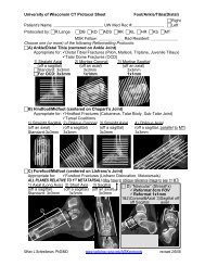
At the UW we have identified at least 15 different ways that<br />
we are commonly asked to create two-dimensional reformatted<br />
images <strong>of</strong> the ankle <strong>and</strong> foot. These are delineated<br />
on our downloadable protocol sheets, portions <strong>of</strong> which<br />
are shown in Figure <strong>47</strong>-<strong>47</strong>. The reformatting protocols are<br />
centered on the anatomic divisions illustrated in Figures<br />
<strong>47</strong>-5 <strong>and</strong> <strong>47</strong>-48.<br />
<strong>Ankle</strong>/Distal Tibia Protocol. Our ankle/distal tibia protocol<br />
(see Fig. <strong>47</strong>-<strong>47</strong>A) is centered on the ankle joint. This<br />
protocol is used for scanning fractures <strong>of</strong> the distal tibia<br />
(e.g., pilon, malleoli, triplane, juvenile Tillaux) or <strong>of</strong> the<br />
talar dome (e.g., osteochondral lesions). Using a midsagittal<br />
reference image, straight axial images are created in a<br />
plane parallel to the bottom <strong>of</strong> the foot. Then, using an<br />
axial reference image through the top <strong>of</strong> the ankle mortise,<br />
mortise coronal <strong>and</strong> mortise sagittal images are created<br />
parallel <strong>and</strong> perpendicular to an imaginary line through<br />
the anterior cortex <strong>of</strong> the medial <strong>and</strong> lateral malleoli. For<br />
distal tibial fractures, we find that creating reformatted<br />
images that are 3 mm thick at 3-mm intervals (no gap or<br />
overlap between reformatted slices) yields crisp images<br />
that do not appear noisy. However, for osteochondral<br />
lesions <strong>of</strong> the talar dome, our surgeons prefer that the<br />
mortise coronal <strong>and</strong> mortise sagittal images be reformatted<br />
at 1 mm, yielding images <strong>of</strong> higher resolution but also with<br />
more noise.<br />
Hindfoot/Midfoot Protocol. Our hindfoot/midfoot protocol<br />
(see Fig. <strong>47</strong>-<strong>47</strong>B) is centered on the Chopart joint <strong>and</strong><br />
is used to evaluate hindfoot fractures (e.g., calcaneus, talar<br />
body) <strong>and</strong> the subtalar joint (e.g., tarsal coalitions). Using<br />
an axial reference image, straight sagittal images are reformatted<br />
along a plane parallel to the long axis <strong>of</strong> the foot.<br />
The other three planes are reformatted <strong>of</strong>f a midsagittal<br />
reference image. Straight axial images are reformatted in a<br />
plane parallel to the bottom <strong>of</strong> the foot. Oblique coronal<br />
<strong>and</strong> oblique axial images are reformatted in planes both<br />
perpendicular <strong>and</strong> parallel to the posterior facet <strong>of</strong> the<br />
subtalar joint.<br />
Forefoot/Midfoot Protocol. Our forefoot/midfoot protocol<br />
(see Fig. <strong>47</strong>-<strong>47</strong>C) is primarily used to assess the alignment<br />
<strong>of</strong> the Lisfranc joint <strong>and</strong> the integrity <strong>of</strong> the adjacent<br />
bones. We find that it works best to create reformatted<br />
images in three planes relative to the first metatarsal shaft.<br />
A sagittal reference image that best delineates the entire<br />
length <strong>of</strong> the first metatarsal is selected. Long-axis <strong>and</strong><br />
short-axis planes are reformatted both parallel <strong>and</strong> perpendicular<br />
to the sagittal length <strong>of</strong> the first metatarsal. The<br />
third plane, sagittal to the first metatarsal, is best obtained<br />
<strong>of</strong>f an axial reference image that has been obliqued to<br />
include the entire length <strong>of</strong> the first metatarsal.<br />
Navicular Protocol. Our dedicated navicular protocol<br />
(see Fig. <strong>47</strong>-<strong>47</strong>D) is used to assess the healing <strong>of</strong> a known<br />
navicular fatigue fracture that has perhaps been previously<br />
diagnosed by MRI. Because these navicular fatigue fractures<br />
tend to be incomplete hairline cracks, we increase the resolution<br />
by creating thin (1 mm) reformatted images in a<br />
small (6 cm) FOV. Oblique coronal <strong>and</strong> oblique axial<br />
Ch0<strong>47</strong>-A05375.indd 2242<br />
9/9/2008 5:34:23 PM