Ankle and Foot 47 - Department of Radiology - University of ...
Ankle and Foot 47 - Department of Radiology - University of ...
Ankle and Foot 47 - Department of Radiology - University of ...

Create successful ePaper yourself
Turn your PDF publications into a flip-book with our unique Google optimized e-Paper software.
2240 VII Imaging <strong>of</strong> the Musculoskeletal System<br />
A<br />
B<br />
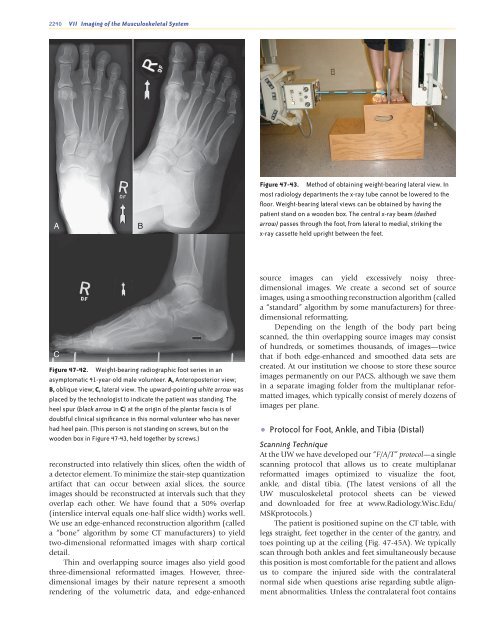
Figure <strong>47</strong>-43. Method <strong>of</strong> obtaining weight-bearing lateral view. In<br />
most radiology departments the x-ray tube cannot be lowered to the<br />
floor. Weight-bearing lateral views can be obtained by having the<br />
patient st<strong>and</strong> on a wooden box. The central x-ray beam (dashed<br />
arrow) passes through the foot, from lateral to medial, striking the<br />
x-ray cassette held upright between the feet.<br />
C<br />
Figure <strong>47</strong>-42. Weight-bearing radiographic foot series in an<br />
asymptomatic 41-year-old male volunteer. A, Anteroposterior view;<br />
B, oblique view; C, lateral view. The upward-pointing white arrow was<br />
placed by the technologist to indicate the patient was st<strong>and</strong>ing. The<br />
heel spur (black arrow in C) at the origin <strong>of</strong> the plantar fascia is <strong>of</strong><br />
doubtful clinical significance in this normal volunteer who has never<br />
had heel pain. (This person is not st<strong>and</strong>ing on screws, but on the<br />
wooden box in Figure <strong>47</strong>-43, held together by screws.)<br />
reconstructed into relatively thin slices, <strong>of</strong>ten the width <strong>of</strong><br />
a detector element. To minimize the stair-step quantization<br />
artifact that can occur between axial slices, the source<br />
images should be reconstructed at intervals such that they<br />
overlap each other. We have found that a 50% overlap<br />
(interslice interval equals one-half slice width) works well.<br />
We use an edge-enhanced reconstruction algorithm (called<br />
a “bone” algorithm by some CT manufacturers) to yield<br />
two-dimensional reformatted images with sharp cortical<br />
detail.<br />
Thin <strong>and</strong> overlapping source images also yield good<br />
three-dimensional reformatted images. However, threedimensional<br />
images by their nature represent a smooth<br />
rendering <strong>of</strong> the volumetric data, <strong>and</strong> edge-enhanced<br />
source images can yield excessively noisy threedimensional<br />
images. We create a second set <strong>of</strong> source<br />
images, using a smoothing reconstruction algorithm (called<br />
a “st<strong>and</strong>ard” algorithm by some manufacturers) for threedimensional<br />
reformatting.<br />
Depending on the length <strong>of</strong> the body part being<br />
scanned, the thin overlapping source images may consist<br />
<strong>of</strong> hundreds, or sometimes thous<strong>and</strong>s, <strong>of</strong> images—twice<br />
that if both edge-enhanced <strong>and</strong> smoothed data sets are<br />
created. At our institution we choose to store these source<br />
images permanently on our PACS, although we save them<br />
in a separate imaging folder from the multiplanar reformatted<br />
images, which typically consist <strong>of</strong> merely dozens <strong>of</strong><br />
images per plane.<br />
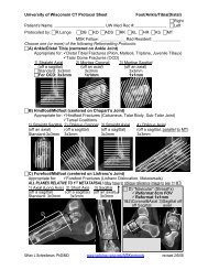
• Protocol for <strong>Foot</strong>, <strong>Ankle</strong>, <strong>and</strong> Tibia (Distal)<br />
Scanning Technique<br />
At the UW we have developed our “F/A/T” protocol—a single<br />
scanning protocol that allows us to create multiplanar<br />
reformatted images optimized to visualize the foot,<br />
ankle, <strong>and</strong> distal tibia. (The latest versions <strong>of</strong> all the<br />
UW musculoskeletal protocol sheets can be viewed<br />
<strong>and</strong> downloaded for free at www.<strong>Radiology</strong>.Wisc.Edu/<br />
MSKprotocols.)<br />
The patient is positioned supine on the CT table, with<br />
legs straight, feet together in the center <strong>of</strong> the gantry, <strong>and</strong><br />
toes pointing up at the ceiling (Fig. <strong>47</strong>-45A). We typically<br />
scan through both ankles <strong>and</strong> feet simultaneously because<br />
this position is most comfortable for the patient <strong>and</strong> allows<br />
us to compare the injured side with the contralateral<br />
normal side when questions arise regarding subtle alignment<br />
abnormalities. Unless the contralateral foot contains<br />
Ch0<strong>47</strong>-A05375.indd 2240<br />
9/9/2008 5:34:17 PM