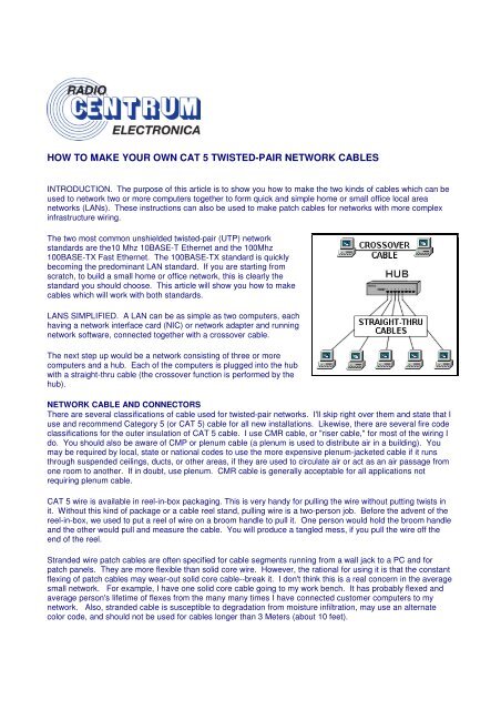
how to make your own cat 5 twisted-pair network ... - RadioCentrum
how to make your own cat 5 twisted-pair network ... - RadioCentrum
how to make your own cat 5 twisted-pair network ... - RadioCentrum

You also want an ePaper? Increase the reach of your titles
YUMPU automatically turns print PDFs into web optimized ePapers that Google loves.
HOW TO MAKE YOUR OWN CAT 5 TWISTED-PAIR NETWORK CABLES<br />
INTRODUCTION. The purpose of this article is <strong>to</strong> s<strong>how</strong> you <strong>how</strong> <strong>to</strong> <strong>make</strong> the two kinds of cables which can be<br />
used <strong>to</strong> <strong>network</strong> two or more computers <strong>to</strong>gether <strong>to</strong> form quick and simple home or small office local area<br />
<strong>network</strong>s (LANs). These instructions can also be used <strong>to</strong> <strong>make</strong> patch cables for <strong>network</strong>s with more complex<br />
infrastructure wiring.<br />
The two most common unshielded <strong>twisted</strong>-<strong>pair</strong> (UTP) <strong>network</strong><br />
standards are the10 Mhz 10BASE-T Ethernet and the 100Mhz<br />
100BASE-TX Fast Ethernet. The 100BASE-TX standard is quickly<br />
becoming the predominant LAN standard. If you are starting from<br />
scratch, <strong>to</strong> build a small home or office <strong>network</strong>, this is clearly the<br />
standard you should choose. This article will s<strong>how</strong> you <strong>how</strong> <strong>to</strong> <strong>make</strong><br />
cables which will work with both standards.<br />
LANS SIMPLIFIED. A LAN can be as simple as two computers, each<br />
having a <strong>network</strong> interface card (NIC) or <strong>network</strong> adapter and running<br />
<strong>network</strong> software, connected <strong>to</strong>gether with a crossover cable.<br />
The next step up would be a <strong>network</strong> consisting of three or more<br />
computers and a hub. Each of the computers is plugged in<strong>to</strong> the hub<br />
with a straight-thru cable (the crossover function is performed by the<br />
hub).<br />
NETWORK CABLE AND CONNECTORS<br />
There are several classifi<strong>cat</strong>ions of cable used for <strong>twisted</strong>-<strong>pair</strong> <strong>network</strong>s. I'll skip right over them and state that I<br />
use and recommend Category 5 (or CAT 5) cable for all new installations. Likewise, there are several fire code<br />
classifi<strong>cat</strong>ions for the outer insulation of CAT 5 cable. I use CMR cable, or "riser cable," for most of the wiring I<br />
do. You should also be aware of CMP or plenum cable (a plenum is used <strong>to</strong> distribute air in a building). You<br />
may be required by local, state or national codes <strong>to</strong> use the more expensive plenum-jacketed cable if it runs<br />
through suspended ceilings, ducts, or other areas, if they are used <strong>to</strong> circulate air or act as an air passage from<br />
one room <strong>to</strong> another. If in doubt, use plenum. CMR cable is generally acceptable for all appli<strong>cat</strong>ions not<br />
requiring plenum cable.<br />
CAT 5 wire is available in reel-in-box packaging. This is very handy for pulling the wire without putting twists in<br />
it. Without this kind of package or a cable reel stand, pulling wire is a two-person job. Before the advent of the<br />
reel-in-box, we used <strong>to</strong> put a reel of wire on a broom handle <strong>to</strong> pull it. One person would hold the broom handle<br />
and the other would pull and measure the cable. You will produce a tangled mess, if you pull the wire off the<br />
end of the reel.<br />
Stranded wire patch cables are often specified for cable segments running from a wall jack <strong>to</strong> a PC and for<br />
patch panels. They are more flexible than solid core wire. However, the rational for using it is that the constant<br />
flexing of patch cables may wear-out solid core cable--break it. I don't think this is a real concern in the average<br />
small <strong>network</strong>. For example, I have one solid core cable going <strong>to</strong> my work bench. It has probably flexed and<br />
average person's lifetime of flexes from the many many times I have connected cus<strong>to</strong>mer computers <strong>to</strong> my<br />
<strong>network</strong>. Also, stranded cable is susceptible <strong>to</strong> degradation from moisture infiltration, may use an alternate<br />
color code, and should not be used for cables longer than 3 Meters (about 10 feet).
Most of the wiring I do simply connects computers directly <strong>to</strong> other computers or hubs. Solid core cable is quite<br />
suitable for this purpose and for many home and small business <strong>network</strong>s. I find it also quite acceptable for use<br />
as patch cables. You might consider a stranded wire patch cable if you have a notebook computer you are<br />
constantly moving around.<br />
CAT 5 cable has four <strong>twisted</strong> <strong>pair</strong>s of wire for a <strong>to</strong>tal of eight individually insulated wires. Each <strong>pair</strong> is color<br />
coded with one wire having a solid color (blue, orange, green, or br<strong>own</strong>) <strong>twisted</strong> around a second wire with a<br />
white background and a stripe of the same color. The solid colors may have a white stripe in some<br />
cables. Cable colors are commonly described using the background color followed by the color of the stripe;<br />
e.g., white-orange is a cable with a white background and an orange stripe.<br />
CONNECTORS. The straight through and cross-over patch cables discussed in this article are terminated with<br />
CAT 5 RJ-45 modular plugs. RJ-45 plugs are similar <strong>to</strong> those you'll see on the end of <strong>your</strong><br />
telephone cable except they have eight versus four or six contacts on the end of the plug<br />
and they are about twice as big. Make sure they are rated for CAT 5 wiring. (RJ means<br />
"Registered Jack"). Also, there are RJ-45 plugs designed for both solid core wire and<br />
stranded wire. Others are designed specifically for one kind of wire or the other. Be sure<br />
you buy plugs appropriate for the wire you are going <strong>to</strong> use. I use plugs designed <strong>to</strong><br />
accommodate both kinds of wire.<br />
NETWORK CABLE TOOLS<br />
Modular Plug Crimp Tool. You will need a modular crimp <strong>to</strong>ol. This one is very similar <strong>to</strong> the one I have been<br />
using for many years for all kinds of telephone cable work and it works just fine for Ethernet cables. You don't<br />
need a lot of bells and whistles, just a <strong>to</strong>ol which will securely crimp RJ-45 connec<strong>to</strong>rs. This one is made by<br />
Eclipse Enterprises, Inc. Even though the crimper has cutters which can be used <strong>to</strong> cut the cable and individual<br />
wires, and possibly stripping the outer jacket, I find that the following <strong>to</strong>ols are better for stripping and cutting<br />
the cable...<br />
Universal UTP Stripping Tool (Eclipse). I recently bought one of these <strong>to</strong>ols and it works slick, and it <strong>make</strong>s a<br />
much neater cut. I recommend that you purchase one if you<br />
will be making many cables.<br />
Diagonal Cutters ("4 <strong>to</strong> 6"). It is easier <strong>to</strong> use diagonal cutters<br />
("diags" or "dikes") <strong>to</strong> cut the cable off at the reel and <strong>to</strong> fine<br />
tune the cable ends during assembly. Also, if you don't have a<br />
stripper, you can strip the cable by using a small knife (X-ac<strong>to</strong>,<br />
utility, etc.) <strong>to</strong> carefully slice the outer jacket longitudinally and use the diags <strong>to</strong> cut it off around the<br />
circumference.<br />
A LITTLE THEORY<br />
The 10BASE-T and 100BASE-TX Ethernets consist of two transmission lines. Each transmission line is a <strong>pair</strong><br />
of <strong>twisted</strong> wires. One <strong>pair</strong> receives data signals and the other <strong>pair</strong> transmits data signals. A balanced line<br />
driver or transmitter is at one end of one of these lines and a line receiver is at the other end. A (much)<br />
simplified schematic for one of these lines and its transmitter and receiver follow:
Pulses of energy travel d<strong>own</strong> the transmission line at about the speed of light (186,000 miles/second). The<br />
principal components of one of these pulses of energy is the voltage potential between wires and current flowing<br />
near the surface of the wires. This energy can also be considered as residing in the magnetic field which<br />
surrounds the wires and the electric field between the wires. In other words, an electromagnetic wave which is<br />
guided by, and travels d<strong>own</strong> the wires.<br />
The main concern is the transient magnetic fields which surrounds the wires and the magnetic fields generated<br />
externally by the other transmission lines in the cable, other <strong>network</strong> cables, electric mo<strong>to</strong>rs, fluorescent lights,<br />
telephone and electric lines, lightning, etc. This is kn<strong>own</strong> as noise. Magnetic fields induce their <strong>own</strong> pulses in a<br />
transmission line which may literally bury the Ethernet pulses, the conveyor of the information being sent d<strong>own</strong><br />
the line.<br />
The <strong>twisted</strong>-<strong>pair</strong> Ethernet employs two principle means for combating noise. The first is the use of balanced<br />
transmitters and receivers. A signal pulse actually consists of two simultaneous pulses relative <strong>to</strong> ground: a<br />
negative pulse on one line and a positive pulse on the other. The receiver detects the <strong>to</strong>tal difference between<br />
these two pulses. Since a pulse of noise (s<strong>how</strong>n in red in the diagram) usually produces pulses of the same<br />
polarity on both lines one pulse is essentially canceled by out the other at the receiver. Also, the magnetic field<br />
surrounding one wire from a signal pulse is a mirror of the one on the other wire. At a very short distance from<br />
the two wires the magnetic fields are opposite and have a tendency <strong>to</strong> cancel the effect of each other out. This<br />
reduces the line's impact on the other <strong>pair</strong> of wires and the rest of the world.<br />
The second and the primary means of reducing cross-talk--the term cross-talk came from the ability <strong>to</strong> (over)<br />
hear conversations on other lines on <strong>your</strong> phone--between the <strong>pair</strong>s in the cable, is the double helix<br />
configuration produced by twisting the wires <strong>to</strong>gether. This configuration produces symmetrical (identical) noise<br />
signals in each wire. Ideally, their difference, as detected at the receiver, is zero. In actuality it is much reduced.<br />
COLOR-CODE STANDARDS<br />
Again, please bear with me... Let's start with simple pin-out diagrams of the two types of UTP Ethernet cables<br />
and watch <strong>how</strong> committees can <strong>make</strong> a can of worms out of them. Here are the diagrams:<br />
Note that the TX (transmitter) pins are connected <strong>to</strong> corresponding RX (receiver) pins, plus <strong>to</strong> plus and minus <strong>to</strong><br />
minus. And that you must use a cossover cable <strong>to</strong> connect units with identical interfaces. If you use a straightthrough<br />
cable, one of the two units must, in effect, perform the cross-over function.<br />
Two wire color-code standards apply: EIA/TIA 568A and EIA/TIA 568B. The codes are commonly<br />
depicted with RJ-45 jacks as follows:
If we apply the 568A color code and s<strong>how</strong> all eight wires, our pin-out looks like this:<br />
Note that pins 4, 5, 7, and 8 and the blue and br<strong>own</strong> <strong>pair</strong>s are not used in either standard. Quite contrary<br />
<strong>to</strong> what you may read elsewhere, these pins and wires are not used or required <strong>to</strong> implement 100BASE-<br />
TX duplexing--they are just plain wasted.<br />
However, the actual cables are not physically that simple. In the diagrams, the orange <strong>pair</strong> of wires are<br />
not adjacent. The blue <strong>pair</strong> is upside-d<strong>own</strong>. The right ends match RJ-45 jacks and the left ends do<br />
not. If, for example, we invert the left side of the 568A "straight"-thru cable <strong>to</strong> match a 568A jack--put one<br />
180° twist in the entire cable from end-<strong>to</strong>-end--and twist <strong>to</strong>gether and rearrange the appropriate <strong>pair</strong>s, we<br />
get the following can-of-worms:<br />
This further emphasizes, I hope, the<br />
importance of the word "twist" in making<br />
<strong>network</strong> cables which will work. You cannot<br />
use a flat-un<strong>twisted</strong> telephone cable for a<br />
<strong>network</strong> cable. Furthermore, you must use a<br />
<strong>pair</strong> of <strong>twisted</strong> wires <strong>to</strong> connect a set of<br />
transmitter pins <strong>to</strong> their corresponding<br />
receiver pins. You cannot use a wire from<br />
one <strong>pair</strong> and another wire from a different<br />
<strong>pair</strong>.<br />
Keeping the above principles in mind, we can simplify the diagram for a 568A straight-thru cable by<br />
untwisting the wires, except the 180° twist in the entire cable, and bending the ends upward. Likewise, if<br />
we exchange the green and orange <strong>pair</strong>s in the 568A diagram we will get a simplified diagram for a 568B<br />
straight-thru cable. If we cross the green and orange <strong>pair</strong>s in the 568A diagram we will arrive at a<br />
simplified diagram for a crossover cable. All three are s<strong>how</strong>n below.<br />
12345678 12345678 12345678 12345678 12345678 12345678<br />
STRAIGHT-THRU<br />
568A<br />
STRAIGHT-THRU<br />
568B<br />
CROSSOVER<br />
568A TO 568B
LET'S MAKE IT SIMPLE<br />
There are only two unique cable ends in the preceding<br />
diagrams. They correspond <strong>to</strong> the 568A and 568B RJ-45<br />
jacks and are s<strong>how</strong>n <strong>to</strong> the right.<br />
Again, the wires with colored backgrounds may have white<br />
stripes and may be denoted that way in diagrams found<br />
elsewhere. For example, the green wire may be labeled<br />
Green-White--I don't bother. The background color is always<br />
specified first.<br />
Now, all you need <strong>to</strong> remember, <strong>to</strong> properly configure the<br />
cables, are the diagrams for the two cable ends and the<br />
following rules:<br />
• A straight-thru cable has identical ends.<br />
• A crossover cable has different ends.<br />
It <strong>make</strong>s no functional difference which standard you use for<br />
a straight-thru cable. You can start a crossover cable with<br />
either standard as long as the other end is the other<br />
standard. It <strong>make</strong>s no functional difference which end is which. Despite what you may have read elsewhere, a<br />
568A patch cable will work in a <strong>network</strong> with 568B wiring and 568B patch cable will work in a 568A<br />
<strong>network</strong>. The electrons couldn't care less.<br />
My preference is <strong>to</strong> use the 568A standard for straight-thru cables and <strong>to</strong> start crossover cables with a 568A<br />
end. That way all I have <strong>to</strong> remember is the diagram for the 568A end, that a straight-thru cable has two of<br />
them, and that the green and orange <strong>pair</strong>s are swapped at the other end of a crossover cable.<br />
LET'S MAKE SOME CABLES<br />
1. Pull the cable off the reel <strong>to</strong> the desired length and cut. I have a box of cable at one end of my shop<br />
and a mark on the floor 10' away. For cable lengths which are a fraction of ten feet, I eye-ball the length<br />
as I pull the cable out of the box (also, my feet are about one foot long). For longer cables, I pull it out <strong>to</strong><br />
the ten foot mark and go back <strong>to</strong> the box and pull the remaining fraction or another ten feet. If you are<br />
pulling cables through walls, a hole in the floor, etc., it easier <strong>to</strong> attach the RJ-45 plugs after the cable is<br />
pulled. The <strong>to</strong>tal length of wire segments between a PC and a hub or between two PC's cannot exceed<br />
100 Meters (328 feet or about the length of a football field) for 100BASE-TX & 300 Meters for 10BASE-T.<br />
2. Strip one end of the cable with the stripper or a knife and diags. If you are using the stripper, place the<br />
cable in the groove on the blade (left) side of the stripper and align the end of the cable with the right side<br />
of the stripper. This is about right <strong>to</strong> strip a little over 1/2" of the jacket off the cable. Turn the stripper about one<br />
turn or so. If you turn it much more, you will probably nick the wires. The idea is <strong>to</strong> score the outer jacket, but<br />
not go all the way through. Once scored, you should be able <strong>to</strong> twist the end of the jacket loose and pull it off<br />
with one hand while holding the rest of the cable with the other. If you are using a knife and diags, carefully slit<br />
the cable for about an inch or so and neatly trim around the circumference of the cable with the diags <strong>to</strong> remove<br />
the jacket.<br />
3. Inspect the wires for nicks. Cut off the end and start over if you see any. You may have <strong>to</strong> adjust the blade<br />
with the screw at the front stripper. Cable diameters and jacket thicknesses vary.
4. Spread and arrange the <strong>pair</strong>s roughly in the order of the desired cable end.<br />
5. Untwist the <strong>pair</strong>s and arrange the wires in the order of the desired cable<br />
end. Flatten the end between <strong>your</strong> thumb and forefinger. Trim the ends of the<br />
wires so they are even with one another.<br />
It is very important that the unstripped (un<strong>twisted</strong>) end be slightly less than 1/2"<br />
long. If it is longer than 1/2" it will be out-of-spec and susceptible <strong>to</strong><br />
crosstalk. If it less than slightly less than 1/2" it will not be properly clinched<br />
when RJ-45 plug is crimped on.. Flatten again. There should be little or no<br />
space between the wires.<br />
6. Hold the RJ-45 plug with the clip facing d<strong>own</strong> or away from you. Push the<br />
wire firmly in<strong>to</strong> the plug. Now, inspect the darn thing... before crimping and wasting the<br />
plug! Looking through the bot<strong>to</strong>m of the plug, the wire on the far left side will have a white<br />
background. The wires should alternate light and dark from left <strong>to</strong> right. The furthest right wire is<br />
br<strong>own</strong>. The wires should all end evenly at the front of the plug. The jacket should end just about<br />
where you see it in the diagram--right on the line. Aren't you glad you didn't crimp the plug?<br />
ALL ABOUT CRIMPING<br />
7. Hold the wire near the RJ-45 plug with the clip d<strong>own</strong> and firmly push it in<strong>to</strong> the left side of the<br />
front of the crimper (it will only go in one way). Hold the wire in place squeeze the crimper handles<br />
quite firmly. This is what will happen:<br />
(Crimp it once.) The crimper pushes two plungers d<strong>own</strong> on the RJ-45 plug. One forces what<br />
amounts <strong>to</strong> a cleverly designed plastic plug/wedge on<strong>to</strong> the cable jacket and very firmly clinches<br />
it. The other seats the "pins," each with two teeth at its end, through the insulation and in<strong>to</strong> the conduc<strong>to</strong>rs of<br />
their respective wires.<br />
8. Test the crimp... If done properly an average person will not be able <strong>to</strong> pull the plug off the cable with his or<br />
her bare hands. And that quite simply, besides lower cost, is the primary advantage of <strong>twisted</strong>-<strong>pair</strong> cables over<br />
the older thinwire, coaxial cables. In fact, I would say the RJ-45 and ease of its installation is the main reason<br />
coaxial cable is no longer widely used for small Ethernets. But, don't pull that hard on the plug. It could stretch<br />
the cable and change its characteristics. Look at the side of the plug and see if it looks like the diagram and<br />
give it a fairly firm tug <strong>to</strong> <strong>make</strong> sure it is crimped well.<br />
9. Prepare the other end of the cable so it has the desired end and crimp.<br />
10. If both ends of the cable are within reach, hold them next <strong>to</strong> each other and with RJ-45 clips facing<br />
away. Look through the bot<strong>to</strong>m of the plugs. If the plugs are wired correctly, and they are identical, it is a<br />
straight-thru cable. If they are wired correctly and they are different, it is a crossover cable.<br />
11. If you have an operational <strong>network</strong>, test the cable. Copy some large files.<br />
12. If the cable doesn't work, inspect the ends again and <strong>make</strong> sure you have the right cable and that it is<br />
plugged in<strong>to</strong> the correct units for the type of cable. Try power-cycling (cold booting) the involved computers.<br />
13. If you have many straight-thru cables and a crossover cable in <strong>your</strong> system, you should consider labeling<br />
the crossover cable or using a different colored cable for the crossover cable so you don't mix them up. I do not<br />
recommend implementing the crossover function, as recommended elsewhere, with two RJ-45 jacks,<br />
appropriately wired back <strong>to</strong> back, and two straight-thru cables. This method costs noticeably more, introduces<br />
more than the necessary number of components and connections, increases the complexity and time of<br />
assembly, and decreases reliability.
1. Try <strong>to</strong> avoid running cables parallel <strong>to</strong> power cables.<br />
CABLING RULES<br />
2. Do not bend cables <strong>to</strong> less than four times the diameter of the cable.<br />
3. If you bundle a group of cables <strong>to</strong>gether with cable ties (zip ties), do not over-cinch them. It's okay <strong>to</strong> snug<br />
them <strong>to</strong>gether firmly; but don't tighten them so much that you deform the cables.<br />
4. Keep cables away from devices which can introduce noise in<strong>to</strong> them. Here's a short list: copy machines,<br />
electric heaters, speakers, printers, TV sets, fluorescent lights, copiers, welding machines, microwave ovens,<br />
telephones, fans, eleva<strong>to</strong>rs, mo<strong>to</strong>rs, electric ovens, dryers, washing machines, and shop equipment.<br />
5. Avoid stretching UTP cables (tention when pulling cables should not exceed 25 LBS).<br />
6. Do not run UTP cable outside of a building. It presents a very dangerous lightning hazard!<br />
7. Do not use a stapler <strong>to</strong> secure UTP cables. Use telephone wire/RJ6 coaxial wire hangers which are<br />
available at most hardware s<strong>to</strong>res.