Electro-Pneumatic - Quia
Electro-Pneumatic - Quia
Electro-Pneumatic - Quia

Create successful ePaper yourself
Turn your PDF publications into a flip-book with our unique Google optimized e-Paper software.
<strong>Electro</strong>-<strong>Pneumatic</strong><br />
Module 2: Direct and Indirect Control in<br />
<strong>Electro</strong>-pneumatics<br />
PREPARED BY<br />
Academic Services<br />
August 2012<br />
© Applied Technology High Schools, 2012
ATM-414 – <strong>Electro</strong>-<strong>Pneumatic</strong><br />
Module 2: Direct and Indirect Control in<br />
<strong>Electro</strong>-pneumatics<br />
Module Objectives<br />
After the completion of this module, the student will be able to:<br />
1- Configure and connect the electrically actuated directional control<br />
valves (solenoid valves).<br />
2- Configure the direct control in electro-pneumatics.<br />
3- Configure the indirect control in electro-pneumatics.<br />
4- Identify the advantages and disadvantages of direct and indirect<br />
control techniques.<br />
5- Simulate and construct simple electric circuits<br />
Module Contents<br />
Number Topic Page No.<br />
1 Solenoid valves 3<br />
2 Types of solenoid valves 5<br />
3 Direct control in electro-pneumatics 6<br />
4 Advantages of direct control 5<br />
5 Disadvantages of direct control 5<br />
5 Practical task 1 7<br />
6 Practical task 2 9<br />
7 Indirect control in electro-pneumatics 15<br />
8 Advantages of direct control 15<br />
9 Disadvantages of direct control 15<br />
10 Practical task 3 17<br />
11 References 22<br />
2 Module 2: Direct and indirect control in electro-pneumatics
ATM-414 – <strong>Electro</strong>-<strong>Pneumatic</strong>s<br />
Electrically-actuated directional<br />
control valves - Solenoid valves:<br />
Introduction:<br />
Two forms of energies are used to operate<br />
any electro-pneumatic control system.<br />
Electrical energy.<br />
Compressed air energy<br />
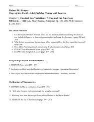
Electrically actuated directional control<br />
valves (DCVs) are switched with the aid of<br />
an electric coil that is called a solenoid. The<br />
electric coil attracts or repels the valve<br />
spool as shown in Fig. 2.1.a.<br />
When the pushbutton switch is pressed<br />
(activated), an electric current flows<br />
through the solenoid coil, the solenoid is<br />
energized causing the valve spool to<br />
move, which in turn will switch the valve<br />
to the second position where the air<br />
flows to move the cylinder piston<br />
forward as illustrated in Fig 2.1.b.<br />
(a)<br />
<br />
Releasing the pushbutton terminates the<br />
current flow, which in turn de-energizes<br />
the solenoid and the DCV moves back to<br />
its normal position.<br />
(b)<br />
Fig.2.1:<br />
(a): Solenoid coil is not activated<br />
(b): Solenoid coil is activated<br />
Module 2: Direct and indirect control in electro-pneumatics 3
ATM-414 – <strong>Electro</strong>-<strong>Pneumatic</strong><br />
Types of solenoid valves<br />
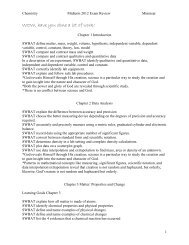
1. Single solenoid valve with a<br />
spring return (reset).<br />
The valve remains in the actuated<br />
position as long as the current<br />
flows through the solenoid.<br />
Example:<br />
5/2 DCV with single solenoid and<br />
spring return, Fig.2.2.<br />
2. Double solenoid valves.<br />
The valve will keep and maintain<br />
the last switched position even<br />
when no current flows through the<br />
solenoid. It is sometimes called<br />
memory valve.<br />
Example:<br />
5/2 DCV, with double solenoid,<br />
Fig. 2.3.<br />
(a)<br />
(b)<br />
(c)<br />
(d)<br />
Fig.2.2:<br />
(a): 5/2 way, single solenoid valve<br />
(b): ISO symbol of 5/2 way single<br />
solenoid valve.<br />
(c): 5/2 way, double solenoid valve<br />
(d): ISO symbol of 5/2 way, double<br />
solenoid valve.<br />
4 Module 2: Direct and indirect control in electro-pneumatics
ATM-414 – <strong>Electro</strong>-<strong>Pneumatic</strong>s<br />
Direct control in electro-pneumatics<br />
Direct control is the control of an electro-pneumatic valve without using<br />
intermediate components such as a relay, a contactor or an industrial<br />
computer (PLC). The valve is connected directly to electric switch as shown<br />
in Fig. 2.3 below<br />
Advantages of direct control<br />
Simple and easy.<br />
Less wiring<br />
Cheap.<br />
Disadvantages of direct control<br />
Remote control is not possible.<br />
Switching more than one valve at a time is not possible.<br />
Latching is not possible.<br />
Design improvement is not flexible.<br />
Fig.2.3 the solenoid valve is connected directly to the switch.<br />
Module 2: Direct and indirect control in electro-pneumatics 5
ATM-414 – <strong>Electro</strong>-<strong>Pneumatic</strong><br />
Practical Task 1<br />
Title:<br />
Direct control of a double acting cylinder by using 5/2 directional<br />
control valve, single solenoid<br />
Objectives:<br />
The student should be able to use 5/2 DCV, single solenoid, with spring<br />
return.<br />
The student should be able to use different electro-pneumatic<br />
equipments.<br />
Background:<br />
A direct control circuit is used to control a 5/2 DCV single solenoid by<br />
using a push button switch. Activating the pushbutton will energize the<br />
coil (solenoid) which in turn will actuate (operate) the valve.<br />
Required components:<br />
1- Double acting cylinder<br />
2- 5/2 way valve, single solenoid<br />
3- Power supply<br />
4- Switches<br />
6 Module 2: Direct and indirect control in electro-pneumatics
ATM-414 – <strong>Electro</strong>-<strong>Pneumatic</strong>s<br />
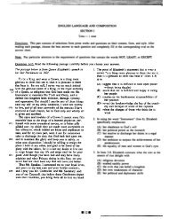
Procedures:<br />
1- Connect the pneumatic circuit<br />
according to the pneumatic circuit<br />
as shown in Fig.2.4.a<br />
2- Connect the electric circuit according<br />
to the electric circuit as shown in<br />
Fig.2.4.b<br />
3- Check that all parts are connected<br />
firmly with each other.<br />
4- Switch on the power from the power<br />
supply and open the service unit.<br />
(a)<br />
5- Press switch S1. Explain what<br />
happens to the cylinder.<br />
...................................................<br />
...................................................<br />
6- Deactivate switch S1 and explain<br />
what happen to the cylinder.<br />
...................................................<br />
...................................................<br />
7- Replace switch S1 with a detent<br />
switch, repeat the steps above and<br />
explain what happen to cylinder.<br />
...................................................<br />
...................................................<br />
8- Turn the power off and close the<br />
service unit.<br />
(b)<br />
Fig.2.4:<br />
(a): <strong>Pneumatic</strong> circuit<br />
(b): Electric circuit<br />
9- Dismantle and tidy up.<br />
Module 2: Direct and indirect control in electro-pneumatics 7
ATM-414 – <strong>Electro</strong>-<strong>Pneumatic</strong><br />
Practical Task 2<br />
Title: Diverting machine<br />
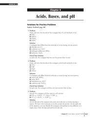
Problem description:<br />
The parts used in the diverting machine are to be moved from one<br />
conveyor track to another conveyor track. By pressing a pushbutton<br />
switch the frame of the diverting machine is pushed forward. The part is<br />
moved over and transported onwards in the opposite direction. By<br />
pressing another pushbutton switch the frame is returned to its start<br />
position as shown below in Fig 2.5<br />
Fig 2.5 Positional sketch of the diverting machine<br />
Procedures:<br />
1. Draw the elector-pneumatic circuit using the FluidSim software<br />
2. Test the circuit functions against any errors or mistakes.<br />
3. Construct the circuit on the workstation<br />
4. Write down your notes and observations.<br />
8 Module 2: Direct and indirect control in electro-pneumatics
D<br />
ATM-414 – <strong>Electro</strong>-<strong>Pneumatic</strong>s<br />
<strong>Pneumatic</strong> circuit<br />
Electric circuit<br />
Observations<br />
............................................................................................................<br />
............................................................................................................<br />
............................................................................................................<br />
............................................................................................................<br />
............................................................................................................<br />
............................................................................................................<br />
............................................................................................................<br />
............................................................................................................<br />
Module 2: Direct and indirect control in electro-pneumatics 9
ATM-414 – <strong>Electro</strong>-<strong>Pneumatic</strong><br />
Class work (1)<br />
1. What is the difference between 5/2 directional control valve, single<br />
solenoid and 5/2 Directional control valve, double solenoid.<br />
2. Draw the I.S.O symbol of:<br />
<br />
5/2 DCV, single solenoid<br />
<br />
5/2 DCV, double solenoid.<br />
10 Module 2: Direct and indirect control in electro-pneumatics
ATM-414 – <strong>Electro</strong>-<strong>Pneumatic</strong>s<br />
3. Draw a pneumatic and an electric circuit to control a double solenoid<br />
valve directly, by using a normally closed detent switch.<br />
<strong>Pneumatic</strong> circuit<br />
Electric circuit<br />
Module 2: Direct and indirect control in electro-pneumatics 11
ATM-414 – <strong>Electro</strong>-<strong>Pneumatic</strong><br />
Home Work (1)<br />
The circuit shown below in Fig 2.6 illustrates an electro-pneumatic<br />
system. Answer the following questions:<br />
Fig 2.6<br />
1. What is the type of switch S1 and S2?<br />
………………………………………………………………………………………………………………………<br />
………………………………………………………………………………………………………………………<br />
2. Is the electric circuit above direct or indirect? Justify your answer<br />
………………………………………………………………………………………………………………………<br />
……………………………………………………………………………………………………………………..<br />
3. What is the name of the part which labeled as Y1?<br />
………………………………………………………………………………………………………………………<br />
……………………………………………………………………………………………………………………..<br />
4. Explain what happen when switch S1 is pressed. Does the cylinder<br />
extend?<br />
12 Module 2: Direct and indirect control in electro-pneumatics
ATM-414 – <strong>Electro</strong>-<strong>Pneumatic</strong>s<br />
………………………………………………………………………………………………………………………<br />
………………………………………………………………………………………………………………………<br />
………………………………………………………………………………………………………………………<br />
5. Explain what happens when switch S2 is pressed. Does the cylinder<br />
extend?<br />
………………………………………………………………………………………………………………………<br />
………………………………………………………………………………………………………………………<br />
………………………………………………………………………………………………………………………<br />
6. Suggest a way to extend the above cylinder rod using the same<br />
electric circuit.<br />
………………………………………………………………………………………………………………………<br />
………………………………………………………………………………………………………………………<br />
………………………………………………………………………………………………………………………<br />
………………………………………………………………………………………………………………………<br />
………………………………………………………………………………………………………………………<br />
………………………………………………………………………………………………………………………<br />
………………………………………………………………………………………………………………………<br />
………………………………………………………………………………………………………………………<br />
Module 2: Direct and indirect control in electro-pneumatics 13
ATM-414 – <strong>Electro</strong>-<strong>Pneumatic</strong><br />
Indirect control in electro pneumatics<br />
Indirect control is the control of an<br />
electro-pneumatic valve using<br />
intermediate components such as<br />
relays, contactors or programmable<br />
logic controllers (PLC).<br />
Advantages of indirect control systems<br />
Remote control is possible<br />
Switching more than one valve at a time is possible<br />
Latching is possible.<br />
Flexible design improvement and development.<br />
Incorporating logic operating conditions (OR, AND conditions)<br />
Disadvantages of direct control<br />
Complicated<br />
More wiring<br />
More cost involved<br />
Practical Task 3 Title: Bulk material<br />
Problem description:<br />
Bulk material is to be emptied from a hopper as shown below in Fig.2.8.<br />
By pressing a pushbutton switch, the hopper is opened and the bulk<br />
material is emptied out. By pressing another pushbutton switch the<br />
hopper is closed again.<br />
Hint: The controlling circuit should contain relays for the indirect control<br />
Fig. 2.8 Positional sketch of the hopper machine<br />
14 Module 2: Direct and indirect control in electro-pneumatics
ATM-414 – <strong>Electro</strong>-<strong>Pneumatic</strong>s<br />
Procedures:<br />
1. Draw the elector-pneumatic circuit using the FluidSim software<br />
2. Test the circuit functions against any errors or mistakes.<br />
3. Construct the circuit on the workstation<br />
4. Write down your notes and observations.<br />
<strong>Pneumatic</strong> circuit<br />
Electric circuit<br />
Observations<br />
............................................................................................................<br />
............................................................................................................<br />
............................................................................................................<br />
............................................................................................................<br />
............................................................................................................<br />
Module 2: Direct and indirect control in electro-pneumatics 15
ATM-414 – <strong>Electro</strong>-<strong>Pneumatic</strong><br />
1. Draw the I.S.O symbol of both<br />
Class work (2)<br />
<br />
A 5/2 DCV, single solenoid.<br />
<br />
A 5/2 DCV, double solenoid.<br />
2. Explain the difference between direct and indirect control.<br />
............................................................................................................<br />
............................................................................................................<br />
............................................................................................................<br />
3. What is the function of a relay?<br />
............................................................................................................<br />
............................................................................................................<br />
............................................................................................................<br />
16 Module 2: Direct and indirect control in electro-pneumatics
ATM-414 – <strong>Electro</strong>-<strong>Pneumatic</strong>s<br />
4. Draw the I.S.O symbols of a relay.<br />
5. Draw a pneumatic and an electric circuit to control a double<br />
solenoid 5/2 DCV indirectly through N.C. relay contacts and<br />
pushbutton switches.<br />
<strong>Pneumatic</strong> circuit<br />
Electric circuit<br />
Module 2: Direct and indirect control in electro-pneumatics 17
ATM-414 – <strong>Electro</strong>-<strong>Pneumatic</strong><br />
Home Work (2)<br />
The circuit below illustrates an electro-pneumatic system. Answer the<br />
following questions:<br />
1. What are the type of the switches S1, S2 and K1?<br />
………………………………………………………………………………………………………………………<br />
………………………………………………………………………………………………………………………<br />
2. Is the electric circuit above direct or indirect? Explain why.<br />
………………………………………………………………………………………………………………………<br />
……………………………………………………………………………………………………………………..<br />
3. What is the name of the part which is labeled as Y1?<br />
………………………………………………………………………………………………………………………<br />
……………………………………………………………………………………………………………………..<br />
4. Explain what happens when the switch S1 is pressed. Does the cylinder<br />
extend? Explain why.<br />
………………………………………………………………………………………………………………………<br />
………………………………………………………………………………………………………………………<br />
18 Module 2: Direct and indirect control in electro-pneumatics
ATM-414 – <strong>Electro</strong>-<strong>Pneumatic</strong>s<br />
5. Explain what happens when the switch S2 is pressed. Does the cylinder<br />
extend? Explain why.<br />
………………………………………………………………………………………………………………………<br />
………………………………………………………………………………………………………………………<br />
6. Explain how to retract the above cylinder.<br />
………………………………………………………………………………………………………………………<br />
………………………………………………………………………………………………………………………<br />
………………………………………………………………………………………………………………………<br />
7. Determine if the following statements are true or false<br />
Number Statements T/F<br />
1 The electric circuit is supplied by AC current<br />
2 The electric circuit has 8 branches<br />
3<br />
A1 and A2 in the electric circuit refer to the relay voltage<br />
terminals<br />
4 K1 in branch 1 refers to a relay contact<br />
5 S1 and S2 in branch1 and branch 3 represent AND gate<br />
References<br />
1. <strong>Electro</strong>-pneumatic text book TP 201 2005 – Festo<br />
2. <strong>Electro</strong>-pneumatic work book TP201 2005 – Festo<br />
3. <strong>Electro</strong>-pneumatic work book TP202 advanced level – Festo<br />
Module 2: Direct and indirect control in electro-pneumatics 19