Handout 7 Unrestrained beams lateral torsional buckling
Handout 7 Unrestrained beams lateral torsional buckling
Handout 7 Unrestrained beams lateral torsional buckling

Create successful ePaper yourself
Turn your PDF publications into a flip-book with our unique Google optimized e-Paper software.
k is an effective length factor (usually 1.0)<br />
k w is an effective length factor (usually 1.0)<br />
z g is the distance between the point of load application<br />
and the shear centre. The value will be positive or<br />
negative depending on where the load is applied as<br />
shown in figure 1.<br />
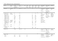
Table 3.1 from SN003 (Values of C1 for members with<br />
end moments)<br />
where<br />
Figure 3.1 from SN003<br />
Summary<br />
Figure 1 (from SN003 document)<br />
C 1 and C 2 are coefficients.<br />
For transverse loading, C1 and C2 are obtained from<br />
Table 5.2 in SN003:<br />
1. Draw the bending moment diagram to obtain the<br />
value of the maximum bending moment, M Ed<br />
2. Determine f y (UK NA recommends you use the<br />
product standards) and calculate the class of the<br />
section. Once you know the class of the section<br />
then you will know which value of the section<br />
modulus you will need to use in the equation 6.55.<br />
3. Work out the effective length, L cr<br />
4. Refer to SN003 document and work out the value<br />
of M cr , the critical moment<br />
5. Work out using expression 6.56.<br />
Table 5.2 from SN003 (C1 and C2 values for<br />
transverse loading)<br />
For members with end moments, the value of C1 is<br />
obtained from Table 3.1 in SN003:<br />
6. Determine the values of α LT<br />
a. For the general case use Table 6.4 to work<br />
out the <strong>buckling</strong> curve and then refer to Table<br />
6.3 to get a value of α LT<br />
b. For the special case, refer to the table in the<br />
National Annex (NA.2.17 Clause 6.3.2.3(1))<br />
to get the <strong>buckling</strong> curve and then refer to<br />
Table 6.3 to get the value of α LT<br />
7. Work out Φ LT<br />
a. For the general case use expression 6.56<br />
b. For the special case, use expression 6.57<br />
8. Work out χ LT<br />
a. For the general case use expression 6.56<br />
b. For the special case, use expression 6.57<br />
9. Calculate the design <strong>buckling</strong> resistance M c,Rd<br />
using equation 6.55.<br />
10. Carry out the <strong>buckling</strong> resistance check in<br />
expression 6.54.