Handout 8 Compression members
Handout 8 Compression members
Handout 8 Compression members

You also want an ePaper? Increase the reach of your titles
YUMPU automatically turns print PDFs into web optimized ePapers that Google loves.
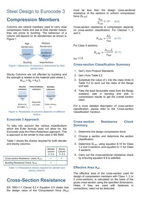
Steel Design to Eurocode 3<br />
<strong>Compression</strong> Members<br />
Columns are vertical <strong>members</strong> used to carry axial<br />
compression loads and due to their slender nature,<br />
they are prone to buckling. The behaviour of a<br />
column will depend on its slenderness as shown in<br />
Figure 1<br />
must be less than the design cross-sectional<br />
resistance of the sections to uniform compression<br />
force (N c,Rd )<br />
(6.9)<br />
Cross-section resistance in compression depends<br />
on cross-section classification. For Classes 1, 2<br />
and 3:<br />
(6.10)<br />
For Class 4 sections:<br />
(6.11)<br />
γ M0 =1.0<br />
Figure 1 Behaviour of columns is determined by their<br />
slenderness<br />
Stocky Columns are not affected by buckling and<br />
the strength is related to the material yield stress f y .<br />
N max = N pl = A eff f y<br />
Figure 2: Resistance of columns depends on different<br />
factors<br />
Eurocode 3 Approach<br />
To take into account the various imperfections<br />
which the Euler formula does not allow for, the<br />
Eurocode uses the Perry-Robertson approach. This<br />
is approach is the similar to that used in BS 5950.<br />
Table 1 shows the checks required for both slender<br />
and stocky columns:<br />
Slender<br />
column<br />
> 0.2<br />
Stocky<br />
Column<br />
< 0.2<br />
Cross-section Resistance check, N c,Rd <br />
Cross-section Classification Summary<br />
1. Get f y from Product Standards<br />
2. Get ε from Table 5.2<br />
3. Substitute the value of ε into the class limits in<br />
Table 5.2 to work out the class of the flange<br />
and web<br />
4. Take the least favourable class from the flange<br />
outstand, web in bending and web in<br />
compression results to get the overall section<br />
class<br />
For a more detailed description of cross-section<br />
classification, please refer to the ‘Cross-section<br />
Classification’ handout.<br />
Cross-section Resistance Check<br />
Summary<br />
1. Determine the design compression force<br />
2. Choose a section and determine the section<br />
classification<br />
3. Determine N c,Rd , using equation 6.10 for Class<br />
1,2 and 3 sections, and equation 6.11 for Class<br />
4 sections.<br />
4. Carry out the cross-sectional resistance check<br />
by ensuring equation 6.9 is satisfied.<br />
Buckling Resistance Check, N b,Rd<br />
<br />
Table 1.0 Resistance checks required for slender and<br />
stocky columns<br />
Cross-Section Resistance<br />
EN 1993-1-1 Clause 6.2.4 Equation 6.9 states that<br />
the design value of the <strong>Compression</strong> force (N Ed )<br />
Effective Area A eff<br />
The effective area of the cross-section used for<br />
design of compression <strong>members</strong> with Class 1, 2 or<br />
3 cross-sections, is calculated on the basis of the<br />
gross cross-section using the specified dimensions.<br />
Holes, if they are used with fasteners in<br />
connections, need not be deducted.
Member Buckling Resistance<br />
EN 1993-1-1 Clause 6.3.1 Equation 6.46 states<br />
that the design values of the <strong>Compression</strong> force<br />
(N Ed ) must be less than the buckling resistance of<br />
the compression member (N b,Rd )<br />
(6.46)<br />
Similarly to cross-section resistance, buckling<br />
resistance is dependent on the cross-section<br />
classification. For sections with Classes 1, 2 and 3:<br />
(6.47)<br />
Non-dimensional Slenderness<br />
For sections with Classes 1, 2 and 3:<br />
(6.50)<br />
or<br />
For Class 4 sections:<br />
(6.51)<br />
or<br />
where<br />
For Class 4 sections:<br />
γ M1 =1.0<br />
Buckling Curves<br />
Buckling curve selection is dependent on the<br />
section geometry. Table 6.2 in EN 1993-1-1<br />
provides guidance on a range of sections.<br />
Effective Buckling Lengths<br />
(6.48)<br />
The effective length of a member will depend on its<br />
end conditions. EC3 gives no direct guidance on<br />
calculating the buckling length, therefore it is<br />
acceptable to use those given in BS 5950 Table<br />
13. Some typical effective lengths are given in<br />
Figure 3.<br />
Imperfection Factor, <br />
is an imperfection factor, first you will need to<br />
determine the required buckling curve from Table<br />
6.2 and refer to Table 6.1 to get the value of :<br />
Buckling Curve a 0 a b c d<br />
Imperfection<br />
Factor<br />
0.13 0.21 0.34 0.49 0.76<br />
EN 1993-1-1 Table 6.1<br />
Reduction Factor, χ<br />
where<br />
(6.49)<br />
Alternatively, χ may be read from Figure 6.4 in the<br />
Eurocodes by using and the required buckling<br />
curve.<br />
Buckling Resistance Check Summary<br />
Pinned -<br />
Pinned<br />
Fixed - Fixed<br />
Fixed - Pinned<br />
Figure 3: Effective Lengths for three types of end<br />
conditions<br />
Elastic Critical Buckling Load<br />
N cr is the elastic critical buckling load for the<br />
relevant buckling mode based on the gross<br />
properties of the cross section<br />
1. Determine the design axial load, N Ed<br />
2. Choose a section and determine the class<br />
3. Calculate the effective length L cr<br />
4. Calculate N cr using the effective length L cr , and<br />
E and I which are section properties<br />
5. Calculate<br />
6. Determine α by first determining the required<br />
buckling curve from Table 6.2 and then reading<br />
off the required value of α from Table 6.1.<br />
7. Calculate Φ by substituting in the values of α<br />
and<br />
8. Calculate χ by substituting in the values of Φ<br />
and<br />
9. Determine the design buckling resistance of<br />
the member by using equation 6.47 or 6.48<br />
and substituting in the value of χ<br />
10. Make sure that the conditions of equation 6.46<br />
are satisfied.