IR Security Beam - Quasar Electronics
IR Security Beam - Quasar Electronics
IR Security Beam - Quasar Electronics

You also want an ePaper? Increase the reach of your titles
YUMPU automatically turns print PDFs into web optimized ePapers that Google loves.
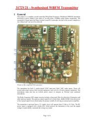
QUASAR PROJECT KIT # 3130v2 - <strong>IR</strong> <strong>Security</strong> <strong>Beam</strong><br />
Use this infrared beam to monitor door & passageways or<br />
other INDOOR areas. When the beam is broken a relay is<br />
tripped which can be used to sound a bell or alarm. Suitable<br />
for detecting customers entering a shop, cars coming up a<br />
driveway, etc. The <strong>IR</strong> beam is very strong. Distances over 15<br />
yards can be monitored indoors. A 12VDC supply is<br />
required to power the kit. A 12V wall adaptor is fine.<br />
Provision has been made so that only one power supply<br />
needs to be used to power both units. The relay output is<br />
rated to switch resistive loads of up to 240Vac or 28Vdc<br />
@ 2 Amp maximum current.*<br />
* For help & safety information on using the relay see:<br />
http://www.quasarelectronics.com/pdf/relay_faq.pdf<br />
CONSTRUCTION<br />
The kit is built on two separate PCBs – a transmitter PCB<br />
(3130T) and a receiver PCB (3130R). Refer to the parts list<br />
to see which components belong to which board. Use the<br />
component overlay on each PCB to place the components.<br />
Transmitter board<br />
Insert the lowest height components first. Leave the infrared<br />
LED and power jack until last. Make sure that the electrolytic<br />
capacitor and 4 diodes are inserted correctly. IC sockets are<br />
supplied for the ICs. Note there are two links to add to the<br />
board. One is under an IC.<br />
The <strong>IR</strong> LED can be mounted vertically or at right angles to<br />
the PCB. This will depend on how the transmitter will be<br />
mounted when in use. In either case the LED must be<br />
inserted the right way round. The flat edge on the LED<br />
should line up with the flat edge on the PCB overlay marked<br />
‘K’.<br />
Lastly, if the distance to be monitored is less than about 10<br />
yards then you will need to fit the 5mm shrink tubing over<br />
the <strong>IR</strong> LED. This narrows the radiating angle of the <strong>IR</strong> beam<br />
and makes it much more directional. The <strong>IR</strong> output is strong.<br />
It can easily bounce off walls etc to give false readings. Note<br />
that the red color shrink tubing is transparent to <strong>IR</strong> and will<br />
not act as <strong>IR</strong> shielding. The black tubing is the one to use.<br />
Receiver board<br />
As with the transmitter board, start with the lowest height<br />
components first - resistors, diodes, capacitors and<br />
transistors. Note the polarity of the electrolytic capacitors and<br />
diodes. Next insert the screw terminal block, power jacks and<br />
relay. Last of all is the infrared receiver module. The<br />
orientation is clearly shown on the PCB overlay: : the<br />
detecting lens bump faces outwards. Power must be center<br />
positive. A protection diode D4 is there to protect the circuit<br />
if the wrong polarity is plugged in.<br />
C<strong>IR</strong>CUIT DESCRIPTION - Transmitter Board<br />
The transmitter board consists of two square-wave<br />
oscillators, one running at approx. 250Hz and the other<br />
running at 38kHz. The 38kHz frequency acts as a carrier<br />
wave and is required by the <strong>IR</strong> receiver module on the<br />
receiver board. This carrier wave is “ANDed” or modulated<br />
by the 250Hz frequency to produce an output signal that<br />
contains bursts of 38kHz at a rate of 250Hz. This signal is<br />
used to drive an infrared LED. The oscillators are made by<br />
PAGE 1<br />
using two 555 timer ICs set up as “astable” (free running)<br />
multivibrators. IC1 is used for the 250Hz oscillator. Resistor<br />
R1 and R2 and capacitor C1 set the frequency. Another 555<br />
chip, IC2, is used for the 38KHz oscillator. Resistors R4 and<br />
R5 and capacitor C3 set the frequency.<br />
Notice the diodes D1 and D3. These are provided to create a<br />
“symmetrical” output. Normally the external capacitor C1<br />
(C3) charges through resistors R1 and R2 (R4 and R5) and<br />
discharges through R2 (R5). Without the diodes this output<br />
waveform would have a longer “high” time than the “low”<br />
time. The diode bypasses resistor R2 (and R5) when the<br />
capacitor is charging, so that it is only charged via R1 (or<br />
R5). This gives the same charging and discharging time and<br />
so the output waveform has equal high and low times.<br />
The charge time (output high) is given by:<br />
T HIGH = 0.693 x R1 x C1 (or 0.693 x R4 x C3)<br />
The discharge time (output low) is given by:<br />
T LOW = 0.693 x R2 x C1 (or 0.693 x R5 x C3)<br />
The output frequency = 1 / (T HIGH + T LOW )<br />
For an excellent website describing all this and more go to<br />
http://www.uoguelph.ca/~antoon/gadgets/555/555.html<br />
For an animation of the 555 as an astable multivibrator see<br />
http://www.williamson-labs.com/480_555.htm<br />
The output from the IC1 is coupled via diode D2 and resistor<br />
R3 to the ‘trigger’ input of IC2. When the IC1 output is low<br />
it stops IC2 from running and IC2’s output is forced high (no<br />
<strong>IR</strong> LED current). When IC1 output is high, IC2 runs and the<br />
<strong>IR</strong> LED is pulsed at 38KHz.<br />
The Waitrony <strong>IR</strong> LED is driven directly from the output of<br />
IC2. Resistor R6 sets the maximum LED current. With a<br />
12VDC supply the current is about 45mA (the LED drops 2V<br />
across it when conducting). Lowering the value of R6 will<br />
increase the current through the LED thus boosting the signal<br />
strength. This may be necessary if the kit is used outside in<br />
direct sunlight or if you need “very long range”. Keep in<br />
mind that the maximum current that the 555 can handle is<br />
200mA. See the <strong>IR</strong> LED data sheet 'ie-0530hp.pdf' at:<br />
http://www.quasarelectronics.com/ds.htm<br />
Receiver Board<br />
The receiver consists of an <strong>IR</strong> receiver module that detects<br />
the incoming <strong>IR</strong> beam from the transmitter. The <strong>IR</strong> signal is<br />
used to keep a capacitor charged which in turn holds a relay<br />
operated. When the beam is broken the capacitor discharges<br />
and the relay releases.<br />
A Kodenshi <strong>IR</strong> receiver/detector module, RX1, is made up of<br />
an an amplifier/filter circuit tuned to detect a 38kHz frequency.<br />
The output pin is low whenever a 38kHz signal is detected.<br />
See the <strong>IR</strong> receiver module data sheet 'pic1018scl.pdf' at:<br />
http://www.quasarelectronics.com/ds.htm
QUASAR PROJECT KIT # 3130v2 - <strong>IR</strong> <strong>Security</strong> <strong>Beam</strong><br />
When the <strong>IR</strong> beam is present the relay is operated.<br />
A cheaper <strong>IR</strong> module from Waitrony we found did not hold<br />
the output signal when the beam was permanently<br />
interrupted.<br />
The output of RX1 is the 250Hz signal from the transmitter.<br />
This signal is passed via transistor Q1, capacitor C1and diode<br />
D2 to capacitor C2. C2 is fully charged during the high<br />
portion of the signal. It starts to discharge during the low<br />
portion of the signal via LED L1, resistor R4 and transistor<br />
Q2. However the discharge time is much longer than the off<br />
time of the signal so the voltage across C2 is always enough<br />
to keep transistor Q2 on and therefore the relay operated.<br />
When the beam is broken the output of RX1 is high.<br />
Transistor Q1 is off and capacitor C2 is no longer being<br />
recharged. It will eventually discharge to the point where<br />
transistor Q2 will turn off and the relay will release. The<br />
“turn off” delay is determined by the time constant of resistor<br />
R5 and capacitor C3. With the values used it is approx. half a<br />
second.<br />
Capacitor C1 prevents a steady DC voltage on the collector<br />
of Q1 from charging C2. This would occur if the beam was<br />
not present or the beam was a continuous 38kHz signal. In<br />
other words, the receiver module will only respond to a<br />
pulsed 38kHz signal.<br />
LED L1 gives a visual indication when the <strong>IR</strong> beam is<br />
present and is used to help with installation and setup. Zener<br />
diode Z1, resistor R6 and capacitor C4 provides a stable 5.6V<br />
supply for the <strong>IR</strong> module. For help with the relay output see:<br />
http://www.quasarelectronics.com/pdf/relay_faq.pdf<br />
INSTALLATION<br />
For ease of operation, the transmitter board can be powered<br />
from the receiver board when they are relatively close<br />
together. Two extra DC plugs have been supplied for this.<br />
Connecting wire for the length required must be supplied by<br />
you. Otherwise two separate power supplies are required.<br />
The receiver board contains two DC jacks connected in<br />
parallel. Power from a 12VDC source is connected to one<br />
jack. A lead can then be connected to the other jack and run<br />
to the transmitter board.<br />
Aligning the transmitter and receiver is a matter of pointing<br />
the transmitter <strong>IR</strong> LED at the receiver board and moving it<br />
around until the red LED on the receiver board lights and the<br />
relay clicks on. This indicates that the beam is being<br />
received.<br />
Note:<br />
With power applied the relay is normally operated and only<br />
releases when the beam is broken. The relay contacts labelled<br />
“NO” (Normally Open) and “NC” (Normally Closed) refer to<br />
when the relay is released. With the relay operated, the “NO”<br />
contact will be connected to the “C” contact and the “NC”<br />
contact will be unconnected.<br />
IF IT DOES NOT WORK<br />
Poor soldering (“dry joints”) is the most common reason that<br />
the circuit does not work. Check all soldered joints carefully<br />
under a good light. Re-solder any that look suspicious. Check<br />
that all components are in their correct position on the PCB.<br />
Are the electrolytic capacitors & diodes around the right way<br />
round? Have you fitted the 5mm tubing to the <strong>IR</strong> LED on the<br />
transmitter board? This is an improved (naturally) version of<br />
the door minder published in Silicon Chip, april, 1999.<br />
New version of this kit released December, 2001.<br />
The transmitter board has been completely revised.<br />
Web Address<br />
http://www.quasarelectronics.com<br />
PARTS LIST – 3130<br />
Transmitter board<br />
Resistors (0.25W 5%, carbon)<br />
220R................................... R6..................................1<br />
1K....................................... R3..................................1<br />
2K2..................................... R4,5...............................2<br />
2K7..................................... R1,2...............................2<br />
Capacitors<br />
10nF ceramic...................... C2,3,4............................3<br />
1uF electrolytic mini .......... C1..................................1<br />
1N4148 signal diode ......... D1,2,3............................3<br />
1N4004 power diode.......... D4..................................1<br />
LM/NE555 Timer IC......... IC1,2..............................2<br />
<strong>IR</strong> LED............................... L1 ..................................1<br />
2.5mm DC jack .................. X1..................................1<br />
IC sockets, 8 pin................. for IC1,2........................2<br />
Tubing, BLACK, 5mm x 25mm long ........................1<br />
(fitted over L1)<br />
PCB, 3130T V2.........................................................1<br />
Receiver Board<br />
Resistors (0.25W 5%, carbon)<br />
470R................................... R3,6...............................2<br />
6K8..................................... R1,2,4............................3<br />
47K..................................... R5..................................1<br />
10uF 25V electrolytic......... C1,2,3............................3<br />
100uF 16V electrolytic....... C4,5...............................2<br />
1N4148 signal diode .......... D1,2...............................2<br />
1N4004 power diode.......... D3, 4..............................2<br />
5.6V 400mW zener diode .. Z1 ..................................1<br />
BC547 transistor, NPN....... Q2..................................1<br />
BC557 transistor, PNP Q1 (might be marked Q3<br />
on the PCB)........................ .......................................1<br />
LED, 5mm red.................... L1 ..................................1<br />
<strong>IR</strong> receiver module............. RX1 ...............................1<br />
2.5mm DC jack .................. X1,2...............................4<br />
Terminal block, 3-way ....... X3..................................1<br />
Relay, 12V SPDT............... RL1................................1<br />
“Goodsky” RWH-SH-112D<br />
PCB, 3130R...............................................................1<br />
PAGE 2
GENERAL RELAY INFORMATION<br />
Warning! Risk of Electric Shock!<br />
This information concerns kits and modules with relay outputs. TO USE THE RELAY OUTPUTS<br />
SAFELY YOU MUST OBSERVE THE MAXIMUM VOLTAGE AND CURRENT LIMITS QUOTED<br />
IN THE PRODUCT DOCUMENTATION (this is because the board design may not be rated to<br />
switch the maximum voltage and current limits printed on the relay itself or specified in the relay<br />
manufacturer’s data sheet).<br />
Controlling mains equipment with relay outputs must be treated with extreme caution. Electric<br />
shocks can cause severe and permanent injury or even death. Construction, installation, testing and commissioning<br />
should only be attempted by suitably qualified persons, or under the supervision of a suitably qualified person. These<br />
products are not suitable for children. Before connecting mains powered equipment to the relay outputs please check<br />
with the relevant authorities in order to ensure compliance with all current safety regulations.<br />
Many areas of the assembly may operate at mains voltage. A suitable isolating enclosure must be used. Exposed screw<br />
terminal blocks on some products must be insulated to prevent contact with exposed metallic parts at mains potential.<br />
Connected equipment should be suitably fused.<br />
You will find relay outputs on many of the kits and modules that we sell. A relay is an electrically<br />
operated on/off switch. The voltage and current limits specified in the product documentation<br />
generally relate to resistive or light inductive loads.<br />
Relay Terminals<br />
Most boards have SPDT (Single Pole Double Throw) style relays. These have three outputs:<br />
C = Common<br />
NO = Normally-Open contacts connect the circuit when the relay is activated; the<br />
circuit is disconnected when the relay is inactive. It is also called a Form A<br />
contact or "make" contact.<br />
NC = Normally-Closed contacts disconnect the circuit when the relay is activated;<br />
the circuit is connected when the relay is inactive. It is also called a Form B<br />
contact or "break" contact.<br />
Connecting the Device you want to Control<br />
You must provide an external power source to the device you want to control. No voltage is present at<br />
the relay terminals (remember it is just a switch). The relay is normally connected in series with the<br />
positive (+) power wire of the device you want to control.<br />
In this case, the positive wire from the power source should be connected to Common. Then either<br />
the NO or NC terminal (as appropriate for your purpose) is connected to the positive (+) wire going to<br />
the device you want to control. The negative (-) wire does not connect to the relay at all. It goes<br />
directly from the power source negative output to the device negative (-) terminal.<br />
Typical SPDT Relay Connection Diagrams<br />
Anti-Spark SPDT Relay Connection Diagram<br />
Sometimes the connected equipment can cause arcing across the relay contacts. This must be<br />
corrected by installing a resistor and capacitor (not supplied) between the two contacts of the relay as<br />
shown below. Component values are for 230Vac mains.<br />
We accept no responsibility for injury, loss, or damage of any kind caused by or resulting from improper product assembly, testing, commissioning or use.
QUASAR PROJECT KIT # 3130v2 - <strong>IR</strong> <strong>Security</strong> <strong>Beam</strong><br />
Door Minder - Receiver Module<br />
Door Minder - Transmitter Module<br />
PAGE 3