1W STEREO KA2209 AMPLIFIER MODULE (3087v2) - Quasar ...
1W STEREO KA2209 AMPLIFIER MODULE (3087v2) - Quasar ...
1W STEREO KA2209 AMPLIFIER MODULE (3087v2) - Quasar ...

Create successful ePaper yourself
Turn your PDF publications into a flip-book with our unique Google optimized e-Paper software.
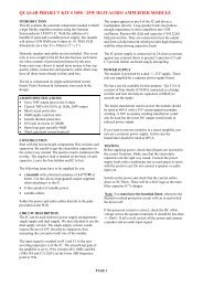
<strong>1W</strong> <strong>STEREO</strong> <strong>KA2209</strong> <strong>AMPLIFIER</strong> <strong>MODULE</strong> (<strong>3087v2</strong>)<br />
T<br />
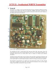
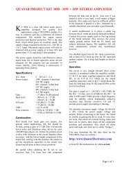
his is a 1 watt stereo amplifier module Kit<br />
using the <strong>KA2209</strong> IC from Samsung, which is<br />
equivalent to the TDA2822. It will operate<br />
well from 3-12V DC and will work from a battery<br />
since the quiescent current drain is low. It requires<br />
no heat sink for normal use. The input and output<br />
are both ground referenced. Maximum output will<br />
be obtained with a 12V power supply and 8 ohm<br />
speaker, however it is particularly suitable for<br />
driving headphones from a supply as low as 3V.<br />
Specifications :<br />
D.C. input : 3 – 12 V at 200 – 500 mA max.<br />
Idle current : ~ 10 mA<br />
Power output : > 1 Watt max. 4-8 ohms, 12V DC<br />
> 500 mW, 32 ohm, 12V<br />
> 500 mW, 4 ohm, 6V<br />
~ 0.4 Watt RMS cont. per channel<br />
Freq. Resp. : ~ 40 Hz to 200 kHz, 8 ohm, G=10<br />
< 20 Hz to > 50 kHz, 32 ohm<br />
THD : < 1 % @ 750 mW, 4-8Ω, 12V<br />
< 0.2 % @ 250 mW, 4-8Ω, 12V<br />
Gain : ~ x10 (20 dB) OR x100 (40dB)<br />
S/N ratio : > 80 dB, G = 20 dB<br />
> 60 dB, G = 40 dB<br />
Sensitivity : < 300 mV, G = 20 dB<br />
< 30 mV, G = 40 dB<br />
Input Z : ~ 10 k ohm<br />
Assembly Instructions :<br />
Assembly is very straight forward, just follow the<br />
PC board overlay. Make sure you get the integrated<br />
circuit and the electrolytic capacitors the correct way<br />
around. The electrolytic capacitors are polarized,<br />
they have a + or - marked on them and they must be<br />
inserted correctly into the PCB. The IC and socket<br />
have a notch at one end, which is marked on the PC<br />
board overlay. If there is no notch on the IC, there<br />
will be a dot next to pin 1, which is the same end.<br />
Solder the socket in place first before installing the<br />
IC itself, then resistors, capacitors, and PCB pins.<br />
Leave the potentiometer until last.<br />
The gain is adjustable from 10 to 100, i.e. 20 to<br />
40 dB. Start with feedback resistors R1 and R3 of 1k<br />
ohm, this will give a gain of 10 which should be<br />
adequate for most applications. If you require more<br />
gain, you can remove resistors R1 and R3. This will<br />
give a gain of approximately 100, or 40 dB. We<br />
have also provided input attenuation via the<br />
potentiometer which can be used as a volume<br />
control. You should keep the IC gain as low as<br />
necessary to achieve full output, with the input<br />
potentiometer and your signal source at maximum.<br />
This will keep the signal to noise ratio as high as<br />
possible. Extra gain provided by the amplifier will<br />
reduce the S/N ratio by a similar amount, since the<br />
input noise figure is constant. Other values for R1<br />
and R3 of between 1k and 10k ohm can be used if<br />
an intermediate gain level is required.<br />
Voltage Gain = 1+ R1/R2 = 1+R3/R4, however the<br />
maximum gain with no external feedback is<br />
approximately 100, or 40dB. (GdB = 20*log Gv)<br />
If driving a pair of headphones, you may also<br />
require a 100 ohm resistor in series with each output<br />
to reduce the output level, depending on headphone<br />
impedance and sensitivity. Make sure you start with<br />
the volume right down to check. A number of<br />
headphones may be driven from the one amplifier if<br />
you wish, since most headphones have at least 16<br />
ohm impedance, or more commonly 32 ohm.<br />
Testing :<br />
Check the voltage and polarity before connecting<br />
the battery or power supply. If it does not work,<br />
recheck all component positions and polarity. Check<br />
all solder joints, and all external wiring. The IC<br />
itself is quite robust, and there is very little else to<br />
go wrong. Remember when testing, it will not<br />
produce full output for more than a short duration<br />
because of limited heat dissipation. We found it<br />
easily exceeded the manufacturers specifications<br />
however.<br />
Circuit Description :<br />
There are only a few external components, the IC<br />
contains most of the necessary circuitry. R1,R2 and<br />
R3,R4 are the feedback resistors. C1 provides power<br />
supply decoupling. C2 and C3 are the input coupling<br />
capacitors, which block any DC that might be<br />
present on the inputs. C4,C5 block DC in the feed<br />
back circuit from the inverting inputs, and C6,C7 are<br />
the output coupling capacitors. C8, R5 and C9,R6<br />
act as zobel networks providing a high frequency<br />
load to maintain stability at frequencies where loud<br />
speaker inductive reactance may become excessive.<br />
The pot provides adjustable input level attenuation.<br />
The data sheet contains further information about<br />
the <strong>KA2209</strong>. You may download it from the<br />
software download page on our website :<br />
http://www.quasarelectronics.com/3087.htm<br />
Page 1 of 3
<strong>1W</strong> <strong>STEREO</strong> <strong>KA2209</strong> <strong>AMPLIFIER</strong> <strong>MODULE</strong> (<strong>3087v2</strong>)<br />
Components :<br />
Capacitors<br />
C1, C2, C3 10 uF / 25V ecap 3<br />
C4, C5 100 uF / 16V ecap 2<br />
C6, C7 470 uF / 16V ecap 2<br />
C8, C9 100 nF box poly 2<br />
Resistors<br />
R1, R3 1k (brown, black, red) 2<br />
R2, R4 100R (brown, black, brown) 2<br />
R5, R6 4R7 ohm (yellow, violet, gold) 2<br />
Pot 1 10k dual gang log pot. (A) 1<br />
Misc.<br />
IC 1 <strong>KA2209</strong> Integrated Circuit 1<br />
3087 Printed Circuit Board 1<br />
8 pin IC socket 1<br />
PCB Pins 9<br />
Page 2 of 3
<strong>1W</strong> <strong>STEREO</strong> <strong>KA2209</strong> <strong>AMPLIFIER</strong> <strong>MODULE</strong> (<strong>3087v2</strong>)<br />
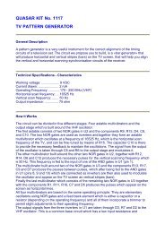
Photo of completed kit.<br />
THD @ 100 mW<br />
12 V supply<br />
32 Ohm Load<br />
G = 20dB<br />
THD @ 750 mW,<br />
12 V supply<br />
8 ohm load<br />
G = 20dB<br />
Page 3 of 3