TDA2009 10W Stereo Audio Amplifier Module (3088) - Quasar ...
TDA2009 10W Stereo Audio Amplifier Module (3088) - Quasar ...
TDA2009 10W Stereo Audio Amplifier Module (3088) - Quasar ...

Create successful ePaper yourself
Turn your PDF publications into a flip-book with our unique Google optimized e-Paper software.
QUASAR PROJECT KIT <strong>3088</strong> - <strong>10W</strong> + <strong>10W</strong> STEREO AMPLIFIER<br />
K<br />
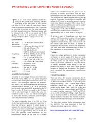
it <strong>3088</strong> is a class AB stereo audio power<br />
amplifier designed for quality hi-fi<br />
applications using a <strong>TDA2009</strong>A module. It is<br />
easy to construct and has a minimum of external<br />
components. The module has output current<br />
protection and thermal protection. This is the data<br />
book circuit which gives an excellent sound. The<br />
supply voltage required for this kit is 8 - 24V DC at<br />
1 to 2 Amps. Maximum output power will only be<br />
obtained with a power supply of at least 20V and<br />
greater than 1.5 A, and using 4 ohm speakers.<br />
The power supply should be well filtered to reduce<br />
mains hum, the on board capacitors alone are not<br />
adequate for this purpose but are necessary to<br />
ensure stability. Extra filtering is unnecessary if<br />
operating from a battery.<br />
Specifications :<br />
D.C. Input :<br />
Power output :<br />
Gain :<br />
Input level :<br />
S/N ratio :<br />
THD :<br />
Freq. response :<br />
Construction.<br />
8 – 24V at 1 – 2 A<br />
<strong>10W</strong> / channel, 4 ohm load<br />
24V DC supply.<br />
6W / channel, 8 ohm load<br />
24V DC supply.<br />
4W / channel, 4 ohm load<br />
12V DC supply.<br />
~ 27 dB or 36 dB optional<br />
~ 300 mV, G = 27 dB<br />
~ 100 mV, G = 36 dB<br />
> 85 dB (G = 27 dB)<br />
> 75 dB (G = 36 dB)<br />
< 0.2 % at 5W<br />
50 kHz –3 dB<br />
~ 10 Hz to 300 kHz G=27dB<br />
First decide how much gain you require. For<br />
general audio applications, R2, R4 should be<br />
56 ohm, giving a gain of 27 dB. This will provide<br />
lower noise and distortion when driven by most<br />
CD/MP3/tape players etc. Follow the printed circuit<br />
overlay with reference to the circuit diagram where<br />
necessary. Add the lowest height components to the<br />
board first, starting with the resistors. Be careful to<br />
get the electrolytic capacitors in the correct way<br />
around and all parts in their correct positions.<br />
between the heat sink & the IC. Also note if you<br />
intend to drive it very hard, it will require a bigger<br />
heatsink. Also make sure there is sufficient airflow<br />
to the heatsink if placed in a box. Alternatively a<br />
suitable aluminium case can make a good heatsink.<br />
A useful modification is to place a solder lug<br />
between the IC metal tab and the heatsink bolthead.<br />
Connect the power supply earth to this lug instead<br />
of the board terminal. This removes the power<br />
supply ground current from the PC board, and<br />
reduces distortion figures. The amplifier will still<br />
work satisfactorily without this modification<br />
however.<br />
Use shielded signal wire for the input connections,<br />
and at least 16/0.2 hook up wire for DC input and<br />
speaker outputs. Try to keep lead lengths as short as<br />
possible<br />
Operation.<br />
The circuit is very straight forward. Most of the<br />
circuitry is contained within the amplifier module.<br />
C1 & C2 are input coupling capacitors and block<br />
DC, as do C10 & C11 which are the output<br />
coupling capacitors, and C6 & C7 which block DC<br />
from the feed back loop. R1/R2 (and R3/R4) set the<br />
level of feed back.<br />
The gain is equal to 1 + (R1/R2) = 68 (37dB) for<br />
R2, R4 = 18 ohm, and 22 (27dB) for R2, R4 = 56<br />
ohm. C8/R5 (and C9/R6) provide a high frequency<br />
load for stability where loudspeaker inductive<br />
reactance may become excessive. C4 and C5<br />
provide power supply decoupling or filtering.<br />
The absolute maximum supply voltage for this Kit<br />
is 28V. Check the power supply voltage and<br />
polarity before connecting to the board. We found<br />
no trouble in getting this kit to work. If yours does<br />
not work, first check all external wiring, make sure<br />
there are no shorts, then check all the component<br />
positions and orientation. Also check all solder<br />
joints and make sure there are no solder “bridges”.<br />
You may download the full data sheet for the<br />
<strong>TDA2009</strong>A from our website :<br />
http://www.<strong>Quasar</strong>Electronics.com<br />
or from ST Microelectronics at : www.st.com<br />
Be careful when soldering the IC not to use<br />
excessive heat. Use some heat sink compound<br />
Page 1 of 1
QUASAR PROJECT KIT <strong>3088</strong> - <strong>10W</strong> + <strong>10W</strong> STEREO AMPLIFIER<br />
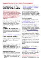
Circuit Diagram<br />
.<br />
Input 1<br />
Input 2<br />
C1<br />
3u3<br />
C2<br />
3u3<br />
+<br />
+<br />
5<br />
1<br />
3<br />
TDA 2009<br />
+<br />
+<br />
-<br />
+<br />
-<br />
9<br />
6<br />
8<br />
4<br />
10<br />
2<br />
C4<br />
100 nF<br />
C6<br />
+<br />
220 uF<br />
C7<br />
+<br />
220 uF<br />
+<br />
C5<br />
100 uF 35V<br />
R1<br />
1k2<br />
R2<br />
56Ω<br />
R3<br />
1k2<br />
R4<br />
56Ω<br />
C10 2200 uF<br />
+<br />
+<br />
Vin<br />
8 - 24V<br />
+<br />
Gnd<br />
C8 35V +<br />
100 nF<br />
R5<br />
1Ω<br />
Speaker 1<br />
(not supplied)<br />
C11 2200 uF<br />
+<br />
C9<br />
100 nF<br />
R6<br />
1Ω<br />
35V<br />
Speaker 2<br />
(not supplied)<br />
C3 22 uF<br />
.<br />
Components<br />
Resistors : 1/2W, 5%.<br />
R1 R3 1K2 (brown red red) 2<br />
R5 R6 1 R (brown black gold) 2<br />
R2 R4 18 R (brown grey black) 2<br />
OR 56 R (green blue black) 2<br />
Capacitors :<br />
3u3 50V mini C1 C2 2<br />
22uF 16V C3 1<br />
100uF 35V C5 1<br />
220uF 10V C6 C7 2<br />
2200uF 35V C10 C11 2<br />
100nF 104 mylar C4 C8 C9 3<br />
<strong>TDA2009</strong>A amp module 1<br />
<strong>3088</strong> Printed Circuit Board 1<br />
Heat sink HS215 or HS110 1<br />
Nut & bolt set for HS 1<br />
3mm Solder lug 1<br />
2 pole terminal block 1<br />
3 pole terminal block 2<br />
Page 2 of 2
QUASAR PROJECT KIT <strong>3088</strong> - <strong>10W</strong> + <strong>10W</strong> STEREO AMPLIFIER<br />
Distortion @ 1W RMS Output<br />
1 kHz input and 24V DC supply:<br />
Photo of completed kit<br />
Page 3 of 3