Computer Dual Unipolar Stepper Motor Driver / Controller (3113)
Computer Dual Unipolar Stepper Motor Driver / Controller (3113)
Computer Dual Unipolar Stepper Motor Driver / Controller (3113)

Create successful ePaper yourself
Turn your PDF publications into a flip-book with our unique Google optimized e-Paper software.
QUASAR PROJECT KIT # <strong>3113</strong> - DUAL STEPPER MOTOR CONTROLLER<br />
INTRODUCTION<br />
This kit enables users to control two unipolar stepper<br />
motors via a parallel/printer port of a PC. Four digital<br />
inputs are also included. These can be used for monitoring<br />
external switches & inputs. The kit itself does not require<br />
any power source. The stepper motors require power.<br />
The kit is designed to fit into an extended D-shell plastic<br />
case. This is also called an RS232 plastic case. A DOS<br />
based program written specifically to drive stepper motors<br />
is included on disk, complete with C source code.<br />
The kit is constructured on a double-sided, through-holeplated<br />
printed circuit board (PCB). Protel Autotrax &<br />
Schematic were used to design the board.<br />
ASSEMBLY INSTRUCTIONS<br />
Start by fitting the two D25 connectors to the PCB. The<br />
male connector fits in position X1. This is the connector<br />
which fits into the parallel port of the PC. The female<br />
connector fits in position X2. Attach these connectors first<br />
for two reasons: access to the pins is easier when none of<br />
the other components are present, & two, you can see<br />
immediately that the PCB will fit in the RS232 case.<br />
Insert the PCB between the two rows of pins on each<br />
connector. Use a flat-bladed screwdriver to spread the<br />
pins apart slightly if required. Make sure the connector<br />
pins are centered on the PCB pads and that the connectors<br />
are the right way around. Push the PCB in until the edge is<br />
touching the plastic housing of each connector. Check that<br />
it fits easily into the case.<br />
Next solder the diodes and resistors into place. Follow the<br />
component overlay on the PCB for placement of<br />
components.<br />
The kit has been supplied with eight 3.3K resistors instead<br />
of a 3.3K 16-pin resnet - resistor network. Bend the legs<br />
of these resistors close to the resistor body and insert them<br />
between the two rows of pins of “RP1”. The first resistor<br />
connects between pins 1 and 16, the second between pins<br />
2 and 15, etc. It does not matter if the resistors sit up<br />
slightly (up to 5mm) above the PCB.<br />
Now fit the transistors. Note that the transistors have a flat<br />
side and a slightly rounded side. Make sure that it is<br />
inserted correctly as outlined on the component overlay.<br />
The tops of transistors should not be more than 5mm<br />
above the surface of the PCB if the case is to fit easily. To<br />
do this one trick is to push them over about 20 o so they<br />
are lower. Bend out the center leg with needle nosed<br />
pliers almost at the body of the transistor in order to get<br />
them fitting lower on the board. Another approach is to<br />
drill out a slot in the case so they can poke through. This<br />
is to be recommended if the steppers you will drive are<br />
over about 2 amps. (See below for more discussion on<br />
this.)<br />
CIRCUIT DESCRIPTION<br />
The circuit consists of eight high-gain NPN transistors<br />
(Q1-8) that are driven via the eight data outputs of the PC<br />
printer port. The transistor outputs are open collector,<br />
which means that the load is connected between the<br />
transistor collector pin and a positive voltage source.<br />
Protection diodes (D1-8) are provided so that the back<br />
EMF generated when driving inductive loads, such as<br />
stepper motors, will not damage the transistors.<br />
Four high voltage inputs (up to 15V) are also included.<br />
Any input voltage above 5.1 volts (nominal) will be<br />
clamped by the 5.1V zener diodes (Z1-4). Resistors, R1-4,<br />
provide current limit protection for the zeners.<br />
The kit is really a digital I/O device with 8 active-low<br />
outputs and 4 protected inputs. The outputs can be used to<br />
switch relays, LEDs, lamps or any other “on-off” device.<br />
It is the software provided with the kit that makes it a<br />
stepper motor controller.<br />
STEPPER MOTORS<br />
<strong>Stepper</strong> motors are a special type of motor. Instead of<br />
rotating smoothly, they move incrementally - in steps.<br />
Each step is a fixed angular displacement of the motor’s<br />
shaft. For example, if the step increment is 3.6 o , then 100<br />
steps are required for a complete 360 o rotation of the<br />
shaft.<br />
There are two types of stepper motors:<br />
1. Bipolar motors. These have two coils and are<br />
controlled by changing the direction of the current<br />
flow through the coils in the proper sequence. These<br />
motors have only four wires and cannot be connected<br />
to this kit. They are declining in availability.<br />
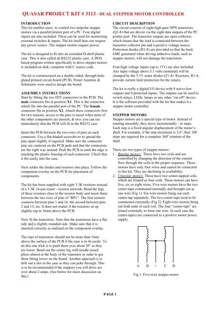
2. <strong>Unipolar</strong> motors. These have two center-tapped coils<br />
which are treated as four coils. These motors can have<br />
five, six or eight wires. Five-wire motors have the two<br />
center-taps commoned internally and brought out as<br />
one wire (Fig 1). Six-wire motors bring out each<br />
center-tap separately. The two center-taps need to be<br />
commoned externally (Fig 2). Eight-wire motors bring<br />
out both ends of each coil. The four “center-taps” are<br />
joined externally to form one wire. In each case the<br />
center-tap(s) are connected to a positive motor power<br />
supply.<br />
A B + C D<br />
Fig 1. Five-wire stepper motor<br />
PAGE 1
QUASAR PROJECT KIT # <strong>3113</strong> - DUAL STEPPER MOTOR CONTROLLER<br />
for a complete rotation. This sequence also suffers<br />
from reduced motor torque because sometimes only<br />
one coil is being used to step the motor.<br />
A B + + C D<br />
Fig 2. Six-wire stepper motor<br />
Step A B C D<br />
1 1 0 0 1<br />
2 1 0 0 0<br />
3 1 1 0 0<br />
4 0 1 0 0<br />
5 0 1 1 0<br />
6 0 0 1 0<br />
7 0 0 1 1<br />
8 0 0 0 1<br />
A + B C + D<br />
Fig 3. Eight-wire stepper motor<br />
<strong>Unipolar</strong> stepper motor sequencing<br />
<strong>Stepper</strong> motors rotate by energizing each coil or coils in<br />
sequence. There are three common sequences used to<br />
drive stepper motors, given in the following tables. In<br />
each case, the steps are repeated when the end of the table<br />
is reached. The direction in which the motor steps<br />
depends on which way the sequence is applied.<br />
1. Two-Phase sequence. This method energizes two coils<br />
at a time which provides the greatest amount of motor<br />
torque. It is the most common method used.<br />
Step A B C D<br />
1 1 1 0 0<br />
2 0 1 1 0<br />
3 0 0 1 1<br />
4 1 0 0 1<br />
2. Wave sequence. This method is also known as wave<br />
drive and only energizes one coil at a time. On some<br />
motors, this gives a smoother motion than the twophase<br />
sequence. However this also means that the<br />
torque of the motor is also reduced.<br />
Step A B C D<br />
1 1 0 0 0<br />
2 0 1 0 0<br />
3 0 0 1 0<br />
4 0 0 0 1<br />
3. Half-step sequence. This sequence interleaves the<br />
normal and wave sequences. This causes the motor to<br />
step at half its normal angle. Therefore a 3.6 o (100<br />
step) motor now steps at 1.8 o and requires 200 steps<br />
PAGE 2<br />
Step rates<br />
<strong>Stepper</strong> motors are mechanical devices and so the rate at<br />
which step pulses are applied is important. The motor<br />
must complete its previous step before the next voltage<br />
sequence is applied. If the step rate is too fast, the motor<br />
may:-<br />
• not move at all<br />
• vibrate instead of step<br />
• rotate erratically - two steps one-way, then 2 back<br />
• rotate in the wrong direction<br />
SIZE OF STEPPER MOTORS<br />
The kit has been tested with a variety of stepper motors.<br />
However, whilst the output transistors have a continuous<br />
collector current rating of 3 amperes, they do get quite<br />
hot when driving large stepper motors. The problem is<br />
even worse when the motor is stationary (not stepping). In<br />
this case one or two coils are permanently energized,<br />
causing large currents to flow through the ‘ON’<br />
transistors.<br />
We have used stepper motors from old 5.25” disk drives<br />
and had them spinning for hours at a time. Total current<br />
consumption is less than 450mA using the two-phase<br />
drive sequence. Current consumption rises to 660mA with<br />
both motors stopped. The transistors barely get warm.<br />
Generally speaking, any stepper motor that draws no more<br />
than one ampere per motor can be connected. You may<br />
need to experiment to determine if the kit can handle<br />
larger motors up to the maximum 3 amp rating of the<br />
transistors. If the transistors heat too much then a<br />
ventilation slot may be required in the case above the<br />
transistors to help cool them. If it is known that a slot is<br />
required then the transistors could be mounted through the<br />
slot.<br />
MOTOR SPEED AND THE BALLAST RESISTOR<br />
<strong>Stepper</strong> motors require a ballast resistor for maximum<br />
speed and quicker response. Most applications will not<br />
need them but others may. <strong>Stepper</strong> motor coils are<br />
inductors which must be charged before the motor can<br />
move. The charge curve for an inductor is a log curve<br />
when a voltage is applied and a straight line when a<br />
constant current is applied. The maximum speed of a<br />
stepper motor is determined partly by how long it takes
QUASAR PROJECT KIT # <strong>3113</strong> - DUAL STEPPER MOTOR CONTROLLER<br />
the coil to charge. Constant current power supplies are<br />
expensive to build. A constant current source can be<br />
approximated by using a ballast resistor in series with a<br />
higher voltage than the motor is rated for.<br />
Ballast resistors are also used to match a higher voltage<br />
power supply to a stepper motor. The value of the resistor<br />
is calculated using the equation:<br />
(Vsupply - Vmotor)<br />
current drawn by motor in use<br />
A typical value of a ballast resistor is 10R, 5W.<br />
CONNECTING A STEPPER MOTOR<br />
Each motor is connected to the kit via X2 using a male<br />
D25 connector. We have supplied this connector and<br />
plastic case. You have to supply the cable and stepper<br />
motors. Use the following chart for pin assignments.<br />
X2 pin <strong>Motor</strong> Coil<br />
1 X A<br />
2 X B<br />
3 X C<br />
4 X D<br />
14, 15, 16, 17 X CENTER-TAP<br />
6 Y A<br />
7 Y B<br />
8 Y C<br />
9 Y D<br />
18, 19, 20, 21 Y CENTER-TAP<br />
10, 11, 12, 13 INPUTS<br />
5 NOT CONNECTED<br />
22, 23, 24, 25 POWER SUPPLY GROUND<br />
Table 1<br />
Note that pins 14-17 and 18-21 also connect to the<br />
positive output of the motor power supply (via a ballast<br />
resistor if necessary). If the same power supply is used for<br />
both motors then common the two supply leads at the<br />
power supply end (see Fig 4).<br />
It is possible to use a different power supply for each<br />
motor. Just connect the positive output of each supply to<br />
pins 14-17 or 18-21 as required. Don’t forget to common<br />
the negative of each supply together and connect to one of<br />
the pins 22-25.<br />
WHICH WIRE IS WHAT?<br />
<strong>Stepper</strong> motors do not usually have each wire labeled.<br />
Also most are obtained by the hobbyist second-hand so<br />
there is no information which comes with them. It is up to<br />
the user to figure it out. The only way to do this is by trial<br />
and error. You will need to use a resistance meter.<br />
Fig 4<br />
Five-wire motor (Fig 1)<br />
Measuring the resistance between the center-tap and any<br />
of the coil ends gives a value which is approximately half<br />
that when measuring across the coil ends.<br />
Pick one wire and measure the resistance between it and<br />
each of the other wires. When you get the same reading all<br />
the time then you have found the center-tap.<br />
Six-wire motor (Fig 2)<br />
The first thing to do here is to separate the six wires into<br />
two groups of three (two center-tapped coils). This is<br />
quickly done by measuring the resistance between each<br />
wire. When there is no reading (open circuit) then the two<br />
wires belong to different groups. Fortunately many<br />
manufacturers already group the six wires into two groups<br />
of 3 as they leave the motor. So you can immediately<br />
move to the next step.<br />
Once separated it is simply a matter of measuring the<br />
resistance between each of the wires in that group to find<br />
the center-tap wire. Join the two center-tap wires together.<br />
Eight-wire motors (Fig 3)<br />
There should be four groups of two wires (four coils).<br />
Measure the resistance between each wire and separate<br />
into groups. Pick a wire from each group and join them all<br />
together. This is the center-tap.<br />
Now that the motor wires have been identified, label each<br />
one as ‘A, B, C, D and CT (center-tap)’. This will help<br />
when connecting to the kit.<br />
PAGE 3
QUASAR PROJECT KIT # <strong>3113</strong> - DUAL STEPPER MOTOR CONTROLLER<br />
PUTTING IT ALL TOGETHER<br />
Using Table 1 and Figure 4, connect each motor to the kit.<br />
Solder each wire to the correct pin on a male D25<br />
connector and then plug it onto connector X2 on the kit.<br />
Don’t forget to connect the power supply wires (positive<br />
and negative).<br />
Plug the kit into the PC parallel port. If you have a 25-way<br />
straight-through cable then use it connect the kit to the PC<br />
port. This will make it easier during the testing stage.<br />
Turn on the power supply and run the software. Is the<br />
software using the same parallel port that you are<br />
connected to?<br />
At the command prompt, type ‘RATE X 1000’ (upper or<br />
lower case). This slows down the step rate to 1 per<br />
second. Now type ‘SPIN X’. <strong>Motor</strong> X should start<br />
rotating, one step every second. If not then the ‘ABCD’<br />
wires may need to be swapped around.<br />
Unfortunately, this is one of those “trial and error”<br />
situations. If the motor had the two groups of wires<br />
identified then there are 4 possible combinations: AB &<br />
CD, AB & DC, BA & CD and BA & DC.<br />
If the groups were not identified then there are 6<br />
combinations: leave A in place - this does not need to be<br />
changed. Then move through BCD, BDC, CBD, CDB,<br />
DBC & DCB.<br />
REMEMBER: Disconnect from PC and power supply<br />
when swapping wires around.<br />
If you have done the above & the motor does not work<br />
correctly the most likely causes are that the wiring is<br />
incorrect somewhere or the soldering is a problem.<br />
As a final recourse check the output voltages going to the<br />
motor. This is best done by an LED & 1K resistor<br />
attached to each motor input & positive of the power<br />
supply (Fig 5). The flashing LED pattern shows when<br />
each coil is energized. No LED’s on means no power is<br />
going to the motor. Any LED pattern should tell you<br />
where the connections need to go. Go to WAVE mode.<br />
Then only one coil should be turned on at a time.<br />
SOFTWARE<br />
The software supplied (DUALSTEP.EXE) enables two<br />
unipolar stepper motors to be controlled with this kit. The<br />
program is DOS-based and was written using Borland<br />
Turbo C 3.0. The “C” source code is also supplied.<br />
You can download the software from our website at:<br />
http://www.... Full address supplied with product<br />
The software has two modes of operation.<br />
1. Standalone mode<br />
To run the program, type:<br />
DUALSTEP <br />
Fig 5. Test circuit<br />
where port = LPT port number (1, 2, 3 or 4). The port<br />
number is optional and defaults to LPT1 if not specified.<br />
eg. ‘DUALSTEP /2’ uses LPT2 as the control port.<br />
2. Batch mode<br />
In this mode, the program processes commands contained<br />
in a text file. Standard DOS I/O redirection is used to<br />
input the commands from the file.<br />
For example.<br />
To process the file “CMDFILE”, use the following<br />
command line:-<br />
DUALSTEP
QUASAR PROJECT KIT # <strong>3113</strong> - DUAL STEPPER MOTOR CONTROLLER<br />
Each command takes effect immediately even if the<br />
previous command has not finished executing. For<br />
example, a STEP command can be issued and while it is<br />
executing, the RATE command can be given to alter the<br />
step rate. The WAIT command has been included to<br />
prevent this - necessary when executing a program from a<br />
text file.<br />
HSTEP motor.....................Set motor to use half-step<br />
drive sequence.<br />
2PHASE motor...................Set motor to use two-phase<br />
drive sequence. This is the<br />
default drive sequence.<br />
WAVE motor......................Set motor to wave drive<br />
sequence<br />
RATE motor val1 ...Set the delay rate between<br />
steps (in milliseconds). Range<br />
from 1 to 50,000.<br />
DIR motor ....Set the direction of rotation.<br />
CW = clockwise<br />
CCW = counter-clockwise.<br />
If no direction is given then it<br />
is reversed.<br />
STEP motor val1 ....Step motor by val1 steps. If<br />
motor is both then val1 refers<br />
to ‘X” and val2 refers to ‘Y’.<br />
WAIT motor.......................Wait for the previous motor<br />
command to finish before<br />
executing the next command<br />
for that motor.<br />
SPIN motor.........................Continuously step motor. Not<br />
affected by ‘WAIT’.<br />
STOP ...................Immediately stop the current<br />
command for motor. If no<br />
motor is specified then stops<br />
both. Ignores ‘WAIT’.<br />
MANUAL ..........................Manually step motors.<br />
Another menu appears.<br />
LOOPTIL input(n) HIGH,LOW<br />
where n=1, 2, 3 or 4.Wait for<br />
the specified input to go high<br />
or low before continuing.<br />
DELAY milliseconds..........Waits the specified delay<br />
time before continuing.<br />
Range = 1 to 50,000.<br />
ECHO ON or OFF .............If ON (default) then all<br />
commands are echoed to the<br />
output.<br />
PRINT message..................to output<br />
VER....................................Print version number<br />
END....................................Wait for all motor commands<br />
to finish then quit<br />
QUIT ..................................Quit program immediately<br />
PARTS LIST - KIT <strong>3113</strong><br />
Resistors (0.25W, 5%)<br />
......................................R1-4..............................4<br />
.....................................H.......................8<br />
Semiconductors<br />
...............................D1-8..............................8<br />
.............................Z1-4..............................4<br />
zeners<br />
.........................Q1-8..............................8<br />
NPN High Gain Transistors<br />
Miscellaneous<br />
D25 connector, male........... X1 ................................. 1<br />
solder type<br />
D25 connector, female........ X2 ................................. 1<br />
solder type<br />
Plastic “D” shell extended covers.............................. 2<br />
............................................<br />
Screws for this case............. ...................................... 2<br />
<strong>3113</strong> PCB........................... ......................................1<br />
Software is available free from our website or call for disk<br />
To connect to stepper motors<br />
D25 connector, male, solder type..............................1<br />
Plastic case for this connector.................................... 1<br />
Ribbon cable....................... ...................................... 2ft<br />
You must supply the stepper motors.<br />
REFERENCES<br />
The Internet is the place to get references and a lot of<br />
technical support. See the Links section of our web site<br />
for a list of sites which discuss stepper motors.<br />
http://www.quasarelectronics.com<br />
- - - - - - - - - - - - - - - - -<br />
HELP..................................Display above summary<br />
PAGE 5
QUASAR PROJECT KIT # <strong>3113</strong> - DUAL STEPPER MOTOR CONTROLLER<br />
PAGE 6