Q CELLS - Installation manual G3 solar modules - Hanwha Q CELLS
Q CELLS - Installation manual G3 solar modules - Hanwha Q CELLS
Q CELLS - Installation manual G3 solar modules - Hanwha Q CELLS

You also want an ePaper? Increase the reach of your titles
YUMPU automatically turns print PDFs into web optimized ePapers that Google loves.
INSTALLATION AND OPERATION MANUAL<br />
CRYSTALLINE SOLAR MODULES<br />
Q.PRO-<strong>G3</strong> · Q.PEAK-<strong>G3</strong> · Q.PEAK BLK-<strong>G3</strong> · Q.PEAK S-<strong>G3</strong><br />
Valid for Africa, Asia, Europe, Latin America, South America
TABLE OF CONTENTS<br />
1 INTRODUCTION 3<br />
2 PLANNING 5<br />
2.1 Technical specifications 5<br />
2.2 Requirements 7<br />
2.3 Mounting options 8<br />
2.4 Electrical layout 10<br />
3 INSTALLATION 11<br />
3.1 Safety and transport 11<br />
3.2 Preparation of installation 13<br />
3.3 Module installation 14<br />
4 ELECTRICAL CONNECTION 15<br />
4.1 Safety 15<br />
4.2 Electrical installation safety 16<br />
4.3 Connection of <strong>modules</strong> 17<br />
4.4 After installation 18<br />
5 GROUNDING 19<br />
6 FAULTS AND DEFECTS 19<br />
7 DISPOSAL 19<br />
8 MAINTENANCE AND CLEANING 20<br />
DOCUMENT REVISION 03<br />
This <strong>Installation</strong> Manual is valid for Africa, Europe, Latin America and South America as of May 1st 2013 for Q.PRO-<strong>G3</strong>,<br />
Q.PEAK-<strong>G3</strong>, Q.PEAK BLK-<strong>G3</strong>, and Q.PEAK S-<strong>G3</strong> and <strong>solar</strong> <strong>modules</strong>, and replaces all earlier versions.<br />
Technical parameters and the design are subject to change. The data sheets and customer information valid at the point in time<br />
when the relevant module was manufactured apply to the installation, mounting, and maintenance procedures for the respective <strong>solar</strong><br />
<strong>modules</strong>.<br />
2 INSTALLATION AND OPERATION MANUAL SOLAR MODULES GENERATION 3 (<strong>G3</strong>) – HANWHA Q <strong>CELLS</strong> GMBH – EN
1 INTRODUCTION<br />
With <strong>solar</strong> <strong>modules</strong> from <strong>Hanwha</strong> Q <strong>CELLS</strong> GmbH (hereafter<br />
referred to as "Q <strong>CELLS</strong>") you can directly transform the<br />
sun’s limitless energy into environmentally-friendly <strong>solar</strong><br />
electricity.<br />
In order to ensure the maximum performance of your Q <strong>CELLS</strong><br />
<strong>solar</strong> <strong>modules</strong>, please read the following instructions carefully<br />
and observe all guidelines. Non-compliance may result<br />
in damage and/or physical injury.<br />
This installation <strong>manual</strong> provides instructions for the safe<br />
installation of crystalline <strong>solar</strong> <strong>modules</strong>.<br />
ÄÄPlease read these instructions carefully before proceeding<br />
with your installation.<br />
ÄÄPlease retain these instructions for the life of the <strong>solar</strong><br />
<strong>modules</strong>.<br />
ÄÄPlease ensure that this installation <strong>manual</strong> is available<br />
to the operator at all times.<br />
ÄÄThis installation <strong>manual</strong> should be given to all subsequent<br />
owners or users of the <strong>solar</strong> <strong>modules</strong>.<br />
ÄÄAll supplements received from the manufacturer should<br />
be included.<br />
ÄÄPlease observe all other applicable documents.<br />
Intended Use<br />
This <strong>manual</strong> is valid for Germany, Austria, and Switzerland.<br />
These instructions contain information regarding the safe<br />
handling and use of quality crystalline <strong>solar</strong> <strong>modules</strong> from<br />
Q <strong>CELLS</strong> and for their installation, mounting, wiring, and<br />
maintenance.<br />
Symbols and Labels<br />
The following symbols and labels are used throughout the<br />
installation <strong>manual</strong> for ease of use.<br />
SYMBOL<br />
Ä Ä<br />
DESCRIPTION<br />
Procedure with one or more steps.<br />
Safety Regulations<br />
The <strong>solar</strong> module operator is responsible for compliance<br />
with all applicable statutory requirements and<br />
regulations.<br />
ÄÄThe following regulations and standards must be upheld<br />
at all times during the installation, operation, and<br />
maintenance of the <strong>solar</strong> <strong>modules</strong>:<br />
• <strong>Installation</strong> and Operation Manual.<br />
• Other applicable documents (such as country-specific<br />
regulations for pressure equipment, operational safety,<br />
hazardous goods, and environmental protection).<br />
• Regulations and requirements specific to the system.<br />
• Applicable country-specific laws, regulations, and<br />
provisions governing the planning, installation, and<br />
operation of <strong>solar</strong> power systems and work on roofs.<br />
• Valid international, national, and regional regulations<br />
governing work with direct current, especially those<br />
applicable to the installation of electrical devices and<br />
systems, and regulations issued by the respective<br />
energy provider governing the parallel operation of<br />
<strong>solar</strong> power systems.<br />
• Accident-prevention regulations.<br />
• Regulations of the Bau-Berufsgenossenschaft (German<br />
institution for statutory accidence insurance<br />
and prevention in the building trade).<br />
Qualified & Skilled Personnel<br />
Both, the operator and installer are responsible for<br />
ensuring that installation, maintenance, connection to<br />
the grid, and dismantling are carried out by trained and<br />
qualified specialists with approved training certificates<br />
(issued by a state or federal organization) for the<br />
respective specialist trade.<br />
Electrical work may only be performed by an officially<br />
certified tradesperson in accordance with the applicable<br />
DIN norms, VDE regulations, accident-prevention regulations,<br />
and the regulations of the local energy provider.<br />
• Lists of items<br />
Ensure that when carrying out a procedure,<br />
you check the results of said procedure.<br />
Prohibited.<br />
Beware of possible danger or damage.<br />
Categories:<br />
• Danger: Risk of fatal injury<br />
• Attention: Risk of serious injury<br />
or damage to property<br />
• Note: Risk of damage to product<br />
INSTALLATION AND OPERATION MANUAL SOLAR MODULES GENERATION 3 (<strong>G3</strong>) – HANWHA Q <strong>CELLS</strong> GMBH – EN 3
1 INTRODUCTION<br />
Validity<br />
These instructions are only valid for crystalline <strong>solar</strong><br />
<strong>modules</strong> from the company Q <strong>CELLS</strong>. Q <strong>CELLS</strong> assumes<br />
no liability for damage resulting from failure to observe<br />
these instructions.<br />
ÄÄPlease observe the wiring and dimensioning of the<br />
system.<br />
ÄÄThe installer of the system is responsible for compliance<br />
with all necessary safety regulations during set-up and<br />
installation.<br />
Q <strong>CELLS</strong> assumes no liability on the basis of these<br />
instructions. Q <strong>CELLS</strong> is only liable in the context of<br />
contractual agreements or in the context of accepted<br />
guarantees. Q <strong>CELLS</strong> accepts no other responsibility for<br />
the functionality and safety of the <strong>modules</strong>.<br />
ÄÄPlease observe the instructions for any other system<br />
components that may be part of the complete<br />
<strong>solar</strong> power system. It may be necessary to carry out a<br />
structural analysis for the entire project.<br />
ÄÄIf your questions are not satisfactorily answered<br />
in the <strong>manual</strong>, please contact your system supplier.<br />
Additional information can be found on our website at<br />
www.q-cells.com.<br />
Information for the Operator<br />
ÄÄPlease keep this <strong>manual</strong> for the entire life of the <strong>solar</strong><br />
power system.<br />
ÄÄPlease contact your system supplier for information<br />
concerning the formal requirements for <strong>solar</strong> power<br />
systems.<br />
ÄÄPlease be sure to contact the relevant local authorities<br />
and energy providers regarding regulations and permit<br />
requirements prior to installation of the <strong>solar</strong> power<br />
system. Your financial success depends on the fulfillment<br />
of these requirements.<br />
Other applicable documents<br />
This installation <strong>manual</strong> is only valid in combination with<br />
the following technical information.<br />
DOCUMENT TYPE<br />
Product data sheet<br />
Packaging and transport of crystalline <strong>modules</strong><br />
4 INSTALLATION AND OPERATION MANUAL SOLAR MODULES GENERATION 3 (<strong>G3</strong>) – HANWHA Q <strong>CELLS</strong> GMBH – EN
2 PLANNING<br />
2.1 Technical specifications<br />
Additional information can be found in the currently valid data sheets available at www.q-cells.com.<br />
PRODUCT LINE Q.PRO-<strong>G3</strong> Q.PEAK-<strong>G3</strong> Q.PEAK BLK-<strong>G3</strong> Q.PEAK S-<strong>G3</strong><br />
Type Polycrystalline Monocrystalline Monocrystalline Monocrystalline<br />
Area [m²] 1.67 1.67 1.67 1.35<br />
Frame height [mm] 35 35 35 35<br />
Weight [kg] 19.0 19.0 19.0 15.5<br />
Max. system voltage V SYS<br />
[V] 1000 1000 1000 1000<br />
Max. reverse current [A] 20 20 20 20<br />
Permissible temperature range<br />
Junction box protection class<br />
–40 °C to +85 °C (–40 °F bis +185 °F)<br />
IP67 with bypass diode<br />
Connector protection class IP68 IP68 IP68 IP68<br />
Fire protection class C C C C<br />
Snow load [Pa] 1 5400 5400 5400 5400<br />
Wind load [Pa] 1 5400 5400 5400 5400<br />
Zertifikate<br />
VDE Quality Tested; CE-compliant; IEC 61215 (Ed.2); IEC 61730 (Ed.1) Application<br />
Class A<br />
1<br />
tested according to IEC 61215<br />
INSTALLATION AND OPERATION MANUAL SOLAR MODULES GENERATION 3 (<strong>G3</strong>) – HANWHA Q <strong>CELLS</strong> GMBH – EN<br />
5
2 PLANNING<br />
150<br />
2.1 Technical specifications<br />
1670<br />
980<br />
6 x Grounding points ø 4.5<br />
Product label<br />
Frame<br />
1210<br />
Cable with<br />
connectors<br />
1000<br />
Junction box<br />
4 x Fastening points, long slot 8 x 16 8 x Drainage holes<br />
Fig. 1:<br />
External dimensions (in mm) and components for Q.PRO-<strong>G3</strong>, Q.PEAK-<strong>G3</strong>, Q.PEAK BLK-<strong>G3</strong><br />
150<br />
1348<br />
788<br />
6 x Grounding points ø 4.5<br />
Product label<br />
Frame<br />
1210<br />
Cable with<br />
connectors<br />
1000<br />
Junction box<br />
4 x Fastening points,<br />
long slot 8 x 16<br />
8 x Drainage holes<br />
Fig. 2:<br />
External dimensions (in mm) and components for Q.PEAK S-<strong>G3</strong><br />
6 INSTALLATION AND OPERATION MANUAL SOLAR MODULES GENERATION 3 (<strong>G3</strong>) – HANWHA Q <strong>CELLS</strong> GMBH – EN
2 PLANNING<br />
2.2 Requirements<br />
<strong>Installation</strong> Site<br />
Please note the following guidelines that apply to the<br />
installation site:<br />
• The <strong>modules</strong> have been tested according to IEC 61215<br />
for operation in a temperate climate.<br />
• Solar <strong>modules</strong> are not explosion-proof.<br />
ÄÄDo not operate <strong>solar</strong> <strong>modules</strong> near highly flammable gas<br />
and vapors (e.g., gas tanks,gas stations).<br />
ÄÄDo not install <strong>modules</strong> in enclosed space.<br />
ÄÄDo not install <strong>modules</strong> in locations where they may be<br />
submerged in water for lengthy periods.<br />
Prevention of Shadowing Effects<br />
Optimal<strong>solar</strong> irradiation leads to maximum energy output:<br />
ÄÄFor this reason, install the <strong>modules</strong> so that they face<br />
the sun.<br />
ÄÄAvoid shadowing (due to objects such as buildings,<br />
chimneys, or trees).<br />
ÄÄAvoid partial shading (for example through overhead<br />
lines, dirt, snow).<br />
Limitations<br />
The <strong>solar</strong> <strong>modules</strong> are designed for the following applications:<br />
• Operating temperatures from –40 °C to +85 °C<br />
(–40 °F to +185 °F).<br />
• Wind and snow loads up to max. 5,400 Pa (as tested<br />
according to IEC 61215).<br />
• <strong>Installation</strong> using a mounting frame for <strong>solar</strong> <strong>modules</strong>.<br />
• Clamps are not in contact with the front glass.<br />
• Clamps do not deform the frame.<br />
• Clamps that satisfy the structural requirements of the<br />
installation site.<br />
• Long-term stable clamps that securely affix the module<br />
to the mounting frame.<br />
Module Orientation Requirements<br />
• Vertical or horizontal installation is permitted.<br />
ÄÄEnsure that rain and melting snow can run off freely.<br />
No water accumulation.<br />
ÄÄEnsure that the drainage holes in the frame are not<br />
covered. No sealing.<br />
ÄÄMaintain the permissible angle of<br />
inclination.<br />
• Minimum angle of inclination: 3°<br />
• Maximum angle of inclination: 80°<br />
• Follow the directions for installation<br />
angles < 5° (“Grounding”, p. 19)<br />
Mounting Frame Requirements<br />
Requirements for the mounting frame:<br />
• Conforms to the necessary structural requirements.<br />
• Compliant with local snow and wind loads.<br />
• Properly fastened to the ground, the roof, or the façade.<br />
• Forces acting on the module are relayed to the mounting<br />
substructure.<br />
• Ensures sufficient rear ventilation of the module.<br />
• Guarantees long-term stability.<br />
• Has electrochemical series that prevent corrosion among<br />
different metals.<br />
• Allows for stress-free expansion and contraction due to<br />
temperature fluctuations.<br />
ÄÄEnsure that no mechanical stresses (e.g., caused by vibrations,<br />
twisting, or expansion) are generated on the module.<br />
ÄÄEnsure that the clamps and the mounting frame are<br />
compatible.<br />
Clamp System Requirements<br />
Use customary clamps that satisfy the following requirements:<br />
• Clamp width: ≥ 40 mm.<br />
• Clamp height compliant with a 35 mm frame height.<br />
• Clamp depth: 7–12 mm.<br />
Inverter<br />
Inverter<br />
• A module with 1,210 mm-long cable can<br />
be wired as a "2nd next neighbor".<br />
"2nd next neighbor" - Wiring without a<br />
return cable.<br />
Standard wiring with a return cable<br />
1<br />
2<br />
INSTALLATION AND OPERATION MANUAL SOLAR MODULES GENERATION 3 (<strong>G3</strong>) – HANWHA Q <strong>CELLS</strong> GMBH – EN<br />
7
2 PLANNING<br />
2.3 Mounting options<br />
Fig. 3: <strong>Installation</strong> options for crystalline Q <strong>CELLS</strong> <strong>modules</strong>. All dimensions are given in mm. Also observe the<br />
allowed static loads and clamping areas as specified on the following page.<br />
The illustrated installation options apply for both horizontal and vertical module orientation.<br />
Module Clamp Subconstruction Mounting profile<br />
TYPE OF<br />
INSTALLATION<br />
MODULE POINT MOUNTING SYSTEM LINEAR MOUNTING SYSTEM<br />
INSTALLATION WITH<br />
CLAMPS<br />
Q.PRO-<strong>G3</strong><br />
Q.PEAK-<strong>G3</strong><br />
Q.PEAK BLK-<strong>G3</strong><br />
245 - 445<br />
245 - 445<br />
0 - 300<br />
0 - 300<br />
Q.PEAK S-<strong>G3</strong><br />
180 - 380<br />
180 - 380<br />
CL1<br />
CL3<br />
CL4<br />
INSTALLATION<br />
ON<br />
MOUNTING<br />
POINTS<br />
Q.PRO-<strong>G3</strong><br />
Q.PEAK-<strong>G3</strong><br />
Q.PEAK BLK-<strong>G3</strong><br />
345<br />
4 x Fastening points<br />
345<br />
4 x Fastening points<br />
Q.PEAK S-<strong>G3</strong><br />
280<br />
4 x Fastening points<br />
280<br />
4 x Fastening points<br />
FB2<br />
FB1<br />
INSTALLATION WITH<br />
INSERTION PROFILES<br />
Q.PRO-<strong>G3</strong><br />
Q.PEAK-<strong>G3</strong><br />
Q.PEAK BLK-<strong>G3</strong><br />
not permitted<br />
Q.PEAK S-<strong>G3</strong><br />
not permitted<br />
IP1<br />
IP2<br />
8 INSTALLATION AND OPERATION MANUAL SOLAR MODULES GENERATION 3 (<strong>G3</strong>) – HANWHA Q <strong>CELLS</strong> GMBH – EN
2 PLANNING 2.3 Mounting options<br />
Specifications<br />
MODULE TYPE MOUNTING OPTION ALLOWED STATIC LOAD 1 [PA] CLAMPING AREA 2 [CM]<br />
Q.PRO-<strong>G3</strong><br />
Q.PEAK-<strong>G3</strong><br />
Q.PEAK BLK-<strong>G3</strong><br />
CL1 Push 2400<br />
3500<br />
Pull 2800<br />
3400<br />
245 - 445<br />
245 - 345<br />
245 - 445<br />
245 - 345<br />
CL3 Push 3200 245 - 445<br />
Pull 3200 245 - 445<br />
CL4 Push 1400 0 - 300<br />
Pull 1400 0 - 300<br />
Q.PEAK S-<strong>G3</strong> CL1 Push 2400<br />
3500<br />
Pull 2800<br />
3400<br />
180 - 380<br />
180 - 280<br />
180 - 380<br />
180 - 280<br />
CL3 Push 3200 180 - 380<br />
Pull 3200 180 - 380<br />
CL4 Push 1400 0 - 300<br />
Pull 1400 0 - 300<br />
Q.PRO-<strong>G3</strong><br />
Q.PEAK-<strong>G3</strong><br />
Q.PEAK BLK-<strong>G3</strong><br />
Q.PEAK S-<strong>G3</strong><br />
FB1 / FB2 Push 3200 -<br />
Pull 3200 -<br />
IP1 Push 3200 -<br />
Pull 3200 -<br />
IP2 Push 1400 -<br />
Pull 1400 -<br />
1<br />
defined vertical to the module area<br />
2<br />
The clamping area is defined as the distance between the outer edge of the module and the middle of the clamp.<br />
SPECIFICATION OF THE CLAMP AREA<br />
ÄÄIn case of varying clamping areas for push and pull loads the smaller clamping area must be applied.<br />
MOUNTING OPTIONS CL1<br />
ÄÄEnsure, that the subconstruction runs below the junction box.<br />
MOUNTING OPTIONS FB1 AND FB2<br />
• The fastening points are located on the back of the frame.<br />
INSTALLATION AND OPERATION MANUAL SOLAR MODULES GENERATION 3 (<strong>G3</strong>) – HANWHA Q <strong>CELLS</strong> GMBH – EN<br />
9
2 PLANNING<br />
2.4 Electrical layout<br />
Module Selection<br />
For detailed key electrical data, please refer to the<br />
product data sheet for the respective product.<br />
ÄÄOnly connect <strong>modules</strong> of the same type and the same<br />
power class.<br />
Safety Factor<br />
During normal operation, a module may generate a greater<br />
current and / or higher voltage than that determined under<br />
standardized test conditions. Please use a safety factor of<br />
1.25 for the following:<br />
• Calculating the voltage measurement values (V oc<br />
) of<br />
components<br />
• Calculating the current measurement values (I SC<br />
) of<br />
conductors<br />
• Sizing of control systems connected to the outlets of<br />
the <strong>solar</strong> <strong>modules</strong><br />
ÄÄPlease follow the valid national guidelines for the<br />
installation of electrical systems.<br />
Series Connection<br />
Connection of <strong>modules</strong> in series is only permitted up to<br />
the maximum system voltage as listed in the applicable<br />
data sheet.<br />
ÄÄTake into account all possible operating situations and all<br />
relevant technical norms and regulations when designing<br />
the system. This will ensure that the maximum system<br />
voltage, including all necessary safety margins, is not<br />
exceeded.<br />
ÄÄTake the voltage limit of the inverter into account when<br />
determining the string length.<br />
Parallel Connection<br />
Modules may be damaged by the occurrence of reverse<br />
currents (caused by module defects, ground leaks, or<br />
defective insulation).<br />
ÄÄEnsure that the maximum reverse current load capacity<br />
indicated in the data sheet is observed.<br />
In order to limit reverse currents that may occur, we<br />
recommend using the following safety options:<br />
1) Layout with a limited number of parallel connected<br />
strings :<br />
Without undertaking further current blocking measures,<br />
a maximum of two module strings may be operated in<br />
parallel on an inverter or MPP tracker.<br />
2) Layout with string diodes :<br />
if more than two strings are connected in parallel, a<br />
respective maximum of two strings must be protected<br />
against reverse currents from the remaining system with<br />
a shared string diode.<br />
3) Layout with string fuses :<br />
place fuses for each string of <strong>modules</strong> at the plus and<br />
minus ends. Observe the maximum permitted number<br />
of strings as indicated in the specifications provided by<br />
the respective string fuse manufacturer and the technical<br />
guidelines.<br />
NOTE!<br />
When installing different product versions, the lowest<br />
minimum permitted reverse current load capacity applies.<br />
Inverters<br />
Inverters with or without transformers may be used.<br />
10 INSTALLATION AND OPERATION MANUAL SOLAR MODULES GENERATION 3 (<strong>G3</strong>) – HANWHA Q <strong>CELLS</strong> GMBH – EN
3 INSTALLATION<br />
3.1 Safety and transport<br />
ÄÄEnsure that all personnel are aware of<br />
and adhere to accident-prevention and<br />
safety regulations.<br />
DANGER! Risk of fatal injury due to electric<br />
shock!<br />
ÄÄDo not install damaged <strong>modules</strong>.<br />
ÄÄInform your dealer of any damages<br />
immediately.<br />
I<br />
§<br />
D<br />
§<br />
GB<br />
§<br />
ÄÄInspect the packaging for damages.<br />
ÄÄContact the transport company regarding<br />
any damage to the packaging.<br />
ÄÄFollow any instructions on the packaging.<br />
DANGER! Risk of fatal injury due to electric<br />
shock!<br />
ÄÄCover the <strong>modules</strong> with an opaque<br />
material during installation.<br />
ÄÄLeave <strong>modules</strong> in their original<br />
packaging until installation.<br />
ÄÄStore the <strong>modules</strong> securely in cool<br />
and dry rooms. The packaging is not<br />
weatherproof.<br />
WARNING! Fire Risk!<br />
ÄÄDo not install <strong>modules</strong> indoors.<br />
ÄÄDo not install <strong>modules</strong> on moving<br />
objects.<br />
INSTALLATION AND OPERATION MANUAL SOLAR MODULES GENERATION 3 (<strong>G3</strong>) – HANWHA Q <strong>CELLS</strong> GMBH – EN 11
3 INSTALLATION<br />
3.1 Safety and transport<br />
NOTE! Module damage may occur!<br />
ÄÄNever lift or move the module with the<br />
connection cables or junction box.<br />
ÄÄCarry <strong>modules</strong> upright and horizontally<br />
as shown.<br />
NOTE! Module damage may occur!<br />
ÄÄNever step on <strong>modules</strong>.<br />
ÄÄDo not subject <strong>modules</strong> to any<br />
mechanical stress.<br />
ÄÄDo not allow any objects to fall onto<br />
<strong>modules</strong><br />
NOTE! Module damage may occur!<br />
ÄÄDo not drop <strong>modules</strong>.<br />
NOTE! Module damage may occur!<br />
ÄÄOnly make modifications to the module<br />
which have been confirmed in writing by<br />
Q <strong>CELLS</strong>.<br />
NOTE! Module damage may occur!<br />
ÄÄDo not stack <strong>modules</strong>.<br />
NOTE! Module damage may occur!<br />
ÄÄDo not install <strong>modules</strong> near flammable<br />
gas / vapors.<br />
12 INSTALLATION AND OPERATION MANUAL SOLAR MODULES GENERATION 3 (<strong>G3</strong>) – HANWHA Q <strong>CELLS</strong> GMBH – EN
3 INSTALLATION<br />
3.2 Preparation of installation<br />
DANGER! Risk of fatal injury due to electric<br />
shock!<br />
ÄÄBlock off the installation zone.<br />
ÄÄKeep children and unauthorized<br />
individuals away from the <strong>solar</strong> power<br />
system.<br />
WARNING! Risk of injury due to falling <strong>modules</strong>!<br />
ÄÄSecure <strong>modules</strong> during installation.<br />
ÄÄDo not install <strong>modules</strong> in windy or wet<br />
weather.<br />
DANGER! Risk of fatal injury due to electric<br />
shock!<br />
ÄÄOnly use dry, insulated tools.<br />
ÄÄDo not carry out the installation alone.<br />
DANGER! Risk of fatal injury due to electric<br />
shock!<br />
ÄÄEnsure that <strong>modules</strong> and tools are not<br />
subject to moisture or rain at any time<br />
during installation.<br />
• Only install undamaged <strong>modules</strong> and<br />
components.<br />
ÄÄDo not drill any other holes.<br />
INSTALLATION AND OPERATION MANUAL SOLAR MODULES GENERATION 3 (<strong>G3</strong>) – HANWHA Q <strong>CELLS</strong> GMBH – EN 13
3 INSTALLATION<br />
3.3 Module installation<br />
Option 1:<br />
ÄÄFasten the module with 4 clamps in the<br />
specified clamping area, see Fig. 3, p.<br />
8.<br />
ÄÄTighten clamps to a torque of 18 Nm.<br />
ÄÄMaintain an interval of at least 10 mm<br />
between two <strong>modules</strong>.<br />
10mm<br />
10mm<br />
Option 2:<br />
ÄÄInstall the module at the 4 mounting<br />
points, see Fig. 3, p. 8.<br />
NOTE! Module damage may occur!<br />
ÄÄDo not subject <strong>modules</strong> to mechanical<br />
tension. Max. torsion 10 mm/m.<br />
Option 3:<br />
ÄÄInstall the module using mounting<br />
profiles, Fig. 3, p. 8.<br />
14 INSTALLATION AND OPERATION MANUAL SOLAR MODULES GENERATION 3 (<strong>G3</strong>) – HANWHA Q <strong>CELLS</strong> GMBH – EN
4 ELECTRICAL CONNECTION<br />
4.1 Safety<br />
DANGER!<br />
Risk of fatal injury due to electric shock!<br />
When disconnecting an electric circuit carrying direct<br />
current, electric arcs can occur that may result in<br />
life-threatening injuries.<br />
ÄÄDo NOT unplug the cable when under load.<br />
ÄÄDo NOT connect any exposed cable ends.<br />
ÄÄDo NOT touch the poles at the same time.<br />
DANGER! Risk of fatal injury due to electric<br />
shock!<br />
ÄÄNever open the junction box.<br />
ÄÄDo not remove bypass diodes.<br />
A <strong>solar</strong> module generates electrical current and voltage<br />
even at a low intensity of illumination. Sparks and electric<br />
arcs may result from the separation of a closed circuit.<br />
These can result in life-threatening injuries. The danger<br />
increases when several <strong>modules</strong> are connected in series.<br />
ÄÄPlease ensure that the entire open circuit voltage is<br />
active even at low levels of <strong>solar</strong> irradiation.<br />
ÄÄPlease follow the valid national regulations and safety<br />
guidelines for the installation of electrical devices and<br />
systems.<br />
ÄÄPlease make sure to take all necessary safety precautions.<br />
With module or phase voltages of more than 120 V, the<br />
extra-low voltage range is exceeded.<br />
ÄÄCarry out work on the inverter and the wiring with extreme<br />
caution.<br />
ÄÄEnsure that the <strong>modules</strong> are disconnected at the inverter<br />
prior to separation.<br />
ÄÄBe sure to observe the specified time intervals after<br />
switching off the inverter. High-voltage components<br />
need time to discharge.<br />
DANGER! Risk of fatal injury due to electric<br />
shock!<br />
ÄÄNever touch live contacts with bare<br />
hands.<br />
ÄÄDo not touch the poles at the same time.<br />
DANGER! Risk of fatal injury due to electric<br />
shock!<br />
ÄÄOnly use dry, insulated tools for electrical<br />
work.<br />
DANGER! Risk of fatal injury due to electric<br />
shock!<br />
ÄÄInsulate any exposed cable ends.<br />
ÄÄOnly connect cables with plugs.<br />
INSTALLATION AND OPERATION MANUAL SOLAR MODULES GENERATION 3 (<strong>G3</strong>) – HANWHA Q <strong>CELLS</strong> GMBH – EN 15
4 ELECTRICAL CONNECTION<br />
4.2 Electrical installation safety<br />
DANGER! Risk of fatal injury due to electric<br />
shock!<br />
ÄÄEnsure correct polarity.<br />
DANGER! Risk of fatal injury due to electric<br />
shock!<br />
ÄÄNever unplug the cable when under load.<br />
1. Switch off the inverter.<br />
DANGER! Risk of fatal injury due to electric<br />
shock!<br />
ÄÄBe sure to maintain the time intervals<br />
as specified between switching off the<br />
inverter and beginning any further work.<br />
2. Cover the <strong>modules</strong> to be disconnected.<br />
3. Switch off the DC circuit breaker.<br />
16 INSTALLATION AND OPERATION MANUAL SOLAR MODULES GENERATION 3 (<strong>G3</strong>) – HANWHA Q <strong>CELLS</strong> GMBH – EN
4 ELECTRICAL CONNECTION<br />
4.3 Connection of <strong>modules</strong><br />
ÄÄUse <strong>solar</strong> cables for the connection at<br />
the junction box outlet.<br />
ÄÄUse the same, inverter-compatible plugs.<br />
NOTE! Module damage may occur!<br />
ÄÄEnsure that the cabling is not under<br />
stress.<br />
ÄÄEnsure that the cables do not run<br />
between module and subconstruction<br />
(danger of pinch).<br />
SOLAR<br />
DANGER! Risk of fatal injury due to electric<br />
shock!<br />
ÄÄEnsure that all electrical components are<br />
in a proper, dry, and safe condition.<br />
ÄÄDo not connect <strong>modules</strong> with different<br />
orientations or angles of inclination in<br />
the same string.<br />
ÄÄEnsure for a tight connection between<br />
the plugs. Plugs click together audibly.<br />
• A module with 1,210 mm-long cable can<br />
be wired as a "2nd next neighbor".<br />
"2nd next neighbor" - Wiring without a<br />
return cable.<br />
Standard wiring with a return cable.<br />
1<br />
Inverter<br />
click<br />
2<br />
Inverter<br />
INSTALLATION AND OPERATION MANUAL SOLAR MODULES GENERATION 3 (<strong>G3</strong>) – HANWHA Q <strong>CELLS</strong> GMBH – EN 17
4 ELECTRICAL CONNECTION<br />
4.4 After installation<br />
ÄÄEnsure that all necessary safety and<br />
functional tests have been carried out<br />
according to current industry standards.<br />
NOTE! Module damage may occur!<br />
ÄÄEnsure that the plug connections are not<br />
level with a water-channeling surface.<br />
ÄÄIntegrate the system into the existing<br />
lightening protection system in<br />
accordance with the applicable local<br />
regulations.<br />
WARNING! Fire Risk!<br />
ÄÄDo not use light concentrators (e.g.<br />
mirrors or lenses).<br />
ÄÄEnsure that the cabling is not exposed<br />
and/or hanging and is protected from dirt<br />
and moisture.<br />
18 INSTALLATION AND OPERATION MANUAL SOLAR MODULES GENERATION 3 (<strong>G3</strong>) – HANWHA Q <strong>CELLS</strong> GMBH – EN
5 GROUNDING<br />
Protective Grounding<br />
ÄÄThe <strong>modules</strong> must be grounded in accordance with the<br />
local statutory regulations.<br />
ÄÄUse Parker screws compliant with DIN 7981, Material<br />
A2, size 5.5 mm x 16 mm.<br />
Stainless Parker screw<br />
Stainless washer (cable lug)<br />
Stainless serrated lock washer<br />
Module frame<br />
6 FAULTS AND DEFECTS<br />
DANGER!<br />
Risk of fatal injury due to electric shock!<br />
ÄÄDo not attempt to fix any problems yourself (e.g.,<br />
glass cracks, damaged cables).<br />
ÄÄPlease contact an installer or Q <strong>CELLS</strong> Technical<br />
Customer Service Department.<br />
ÄÄFasten the protective grounding to the<br />
grounding points with a Parker screw.<br />
7 DISPOSAL<br />
ÄÄDo not disconnect <strong>modules</strong> yourself.<br />
ÄÄPlease commission a trade specialist.<br />
ÄÄPlease ask your installer whether your <strong>modules</strong> are eligible<br />
for the PV Cycle (www.pvcycle.com) disposal program.<br />
ÄÄDispose of <strong>modules</strong> in accordance with the local disposal<br />
regulations.<br />
2<br />
1<br />
3<br />
1<br />
4<br />
Functional grounding<br />
• When using an installation tilt of < 5° a functional<br />
grounding at the negative generator conncetion must<br />
be implemented.<br />
ÄÄEnsure that the difference of potential between the<br />
negative generator connection and the PE(N) of every<br />
MPP tracker of the respective inverters is 0 V.<br />
ÄÄFollow the directions of the inverter manufacturer.<br />
ÄÄOnly use inverters which include lincensed grounding<br />
kits.<br />
INSTALLATION AND OPERATION MANUAL SOLAR MODULES GENERATION 3 (<strong>G3</strong>) – HANWHA Q <strong>CELLS</strong> GMBH – EN 19
8 ELECTRICAL CONNECTION<br />
Q <strong>CELLS</strong> <strong>solar</strong> <strong>modules</strong> are known for a long operating<br />
life and minimal maintenance effort and expense. Dirt<br />
and grime are usually washed away by rain. If the module<br />
is fully or partially shaded by dirt or debris (e.g., plants,<br />
bird droppings), it needs to be cleaned to prevent a loss<br />
of performance.<br />
NOTE! Module damage may occur!<br />
ÄÄDo not clean <strong>modules</strong> with water if there<br />
is a risk of frost.<br />
Maintenance<br />
ÄÄThe system should be inspected by an installer annually<br />
to check the following:<br />
• all system components sit securely and are corrosion<br />
free.<br />
• the connection is secure and all electrical components<br />
are clean and undamaged.<br />
Cleaning<br />
0°<br />
WARNING!<br />
Risk of injury due to hot and<br />
live <strong>modules</strong>!<br />
ÄÄOnly clean <strong>modules</strong> that have cooled down.<br />
ÄÄDo not carry or wear any electrically conductive parts.<br />
WARNING!<br />
Risk of falling due to unsecured<br />
access!<br />
ÄÄNever access the installation area alone or without<br />
taking adequate security precautions.<br />
ÄÄPlease commission a trade specialist.<br />
ÄÄRemove dirt with lukewarm water, a<br />
broom, or a soft cloth.<br />
ÄÄDo not use tensides, scrapers, or any<br />
high-pressure water cleaning equipment.<br />
Clean the <strong>modules</strong> as follows:<br />
ÄÄRemove snow and ice without force (e.g. with a broom).<br />
ÄÄDo not scratch off dirt.<br />
ÄÄRinse dirt off with lukewarm water (dust, leaves, etc.)<br />
ÄÄUse a soft cellulose cloth (kitchen roll) or sponge to<br />
carefully wipe off stubborn dirt. Do not use micro fleece<br />
wool or cotton cloths.<br />
ÄÄUse an alcohol based glass cleaner. Do not use abrasive<br />
detergents or tensides.<br />
ÄÄIsopropyl alcohol (IPA) can be used selectively to remove<br />
stubborn dirt and stains.<br />
ÄÄPlease follow the safety guidelines provided by the IPA<br />
manufacturer.<br />
ÄÄDo not let IPA run down between the module and the<br />
frame or into the module edges.<br />
ÄÄFree the substructure from any dirt and<br />
debris (leaves, bird nests, etc.).<br />
20 INSTALLATION AND OPERATION MANUAL SOLAR MODULES GENERATION 3 (<strong>G3</strong>) – HANWHA Q <strong>CELLS</strong> GMBH – EN
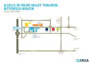
CONTACT<br />
HANWHA Q <strong>CELLS</strong> GMBH<br />
OT Thalheim<br />
Sonnenallee 17-21<br />
06766 Bitterfeld-Wolfen<br />
Germany<br />
TEL +49 (0)3494 66 99 - 23222<br />
FAX +49 (0)3494 66 99 -23002<br />
E-MAIL service@q-cells.com<br />
WEB www.q-cells.com<br />
Subject to change without notice. © <strong>Hanwha</strong> Q <strong>CELLS</strong> GmbH <strong>Installation</strong> <strong>manual</strong> <strong>G3</strong> <strong>modules</strong>_2013-05_Rev03_EN