The Influence of Micro Cracks in Multi-Crystalline Silicon ... - Q-Cells
The Influence of Micro Cracks in Multi-Crystalline Silicon ... - Q-Cells
The Influence of Micro Cracks in Multi-Crystalline Silicon ... - Q-Cells

Create successful ePaper yourself
Turn your PDF publications into a flip-book with our unique Google optimized e-Paper software.
THE INFLUENCE OF MICRO CRACKS IN<br />
MULTI-CRYSTALLINE SILICON SOLAR<br />
CELLS ON THE RELIABILITY OF PV<br />
MODULES<br />
P. Grunow 1 , P. Clemens 1 , V. H<strong>of</strong>fmann 1 , B. Litzenburger 2 , L. Podlowski 2<br />
1<br />
Q-<strong>Cells</strong> AG, Guardianstr. 16, D-06766 Thalheim, Germany, phone: +49 3494 6686 -0, fax: -10, email: p.grunow@q-cells.com<br />
2<br />
Solon PV GmbH, Ederstr. 16, D-12059 Berl<strong>in</strong>, Germany, phone: +49 30 818 79 -100, fax: -110, email: l.podlowski@solon-pv.com; b.litzenburger@solon-pv.com<br />
Motivation<br />
<strong>The</strong> need to produce more Wp per kg silicon <strong>in</strong> a period<br />
<strong>of</strong> poly silicon shortage has lead to rigid thickness<br />
reductions for mono- and multicrystall<strong>in</strong>e silicon wafers.<br />
<strong>Micro</strong> cracks <strong>in</strong> wafers and cells are therefore<br />
<strong>in</strong>vestigated with special effort [1][2], because they<br />
limit the production yields and they are suspected to<br />
reduce the module reliability.<br />
Wafers with different thickness were lam<strong>in</strong>ated on<br />
module cover glass for bend<strong>in</strong>g tests and the<br />
propagation <strong>of</strong> micro cracks was detected by near<br />
<strong>in</strong>frared scatter<strong>in</strong>g (NIRS). In difference to conventional<br />
approaches [3], NIRS detects the reflection at the micro<br />
crack <strong>in</strong>duced <strong>in</strong>ternal <strong>in</strong>terfaces <strong>in</strong> the wafer material.<br />
Experimental: module bend<strong>in</strong>g tester and NIRS<br />
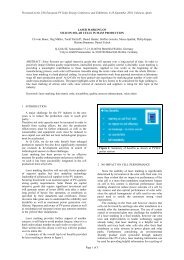
Fig. 1:. Module bend<strong>in</strong>g tester with adjustable elongation<br />
between 0 and 12 cm. <strong>The</strong> load was <strong>in</strong>creased <strong>in</strong> 1 cm<br />
steps and the lam<strong>in</strong>ated wafers were monitored <strong>in</strong> respect<br />
to micro crack occurance by NIRS, i.e. scattered light <strong>in</strong><br />
the near <strong>in</strong>frared range transmitt<strong>in</strong>g the wafer.<br />
A conventional digital camera with switched <strong>of</strong>f IR filter<strong>in</strong>g<br />
was used together with a halogene bulb as light source.<br />
Fig. 2: NIR Scatter<strong>in</strong>g image <strong>of</strong> a wafer lam<strong>in</strong>ated on glass<br />
show<strong>in</strong>g micro cracks after mechanical load<strong>in</strong>g <strong>in</strong> the module<br />
bend<strong>in</strong>g test. In difference to the conventional transmission<br />
technique, the cracks appear dark <strong>in</strong> the NIRS image.<br />
<strong>The</strong> cross <strong>in</strong> the center was prepared by laser scrib<strong>in</strong>g with a<br />
def<strong>in</strong>ed groove length (20mm) and depth (120µm) before the<br />
bend<strong>in</strong>g test as a def<strong>in</strong>ed reference damage.<br />
Mechanical bend<strong>in</strong>g tests<br />
Fig 3: <strong>The</strong> elongation from the module bend<strong>in</strong>g tester was used<br />
to calculate the curvature radius us<strong>in</strong>g the deflection curve <strong>of</strong> a<br />
simple beam. <strong>The</strong> critical radius def<strong>in</strong>ed by the first occurence<br />
<strong>of</strong> micro cracks as propagat<strong>in</strong>g from the laser scribed grooves is<br />
compared to the value reached <strong>in</strong> the mechanical load tests<br />
accord<strong>in</strong>g to IEC 61215. <strong>The</strong> thermal cycl<strong>in</strong>g tests were<br />
performed <strong>in</strong> parallel and turned out to be less critical<br />
regard<strong>in</strong>g tensile stress on cells <strong>in</strong> the considered module<br />
Electrical Measurements<br />
#1 #2<br />
Fig. 6: Q6L multicrystall<strong>in</strong>e s<strong>in</strong>gle-cell-modules, that were<br />
prepared with different crack positions <strong>in</strong>duced by<br />
scratch<strong>in</strong>g the module back sheet with a metal stick<br />
Type crack position<br />
#3<br />
?<br />
#4 #5 #6<br />
#1 parallel on both sides ot both bus bars<br />
#2 parallel to one bus bar outside<br />
#3 corner<br />
#4 position unknown, natural crack from bend<strong>in</strong>g<br />
#5 parallel and centered between the bus bars<br />
#6 centered but perpendicular to the bus bars<br />
Table 1: Different crack position as sketched <strong>in</strong> Fig. 5<br />
change<br />
critical curvature radius/cm<br />
600<br />
500<br />
400<br />
300<br />
200<br />
100<br />
0<br />
220 µm<br />
270 µm<br />
IEC 61215 heavy load test 540 kg/m²<br />
0 200 400 600 800 1000<br />
groove length/ µm<br />
Fig. 4: Module bend<strong>in</strong>g tests for multicrystall<strong>in</strong>e wafers<br />
with 280 and 220 µm thickness lam<strong>in</strong>ated on glass<br />
with one EVA layer and prepared with laser grooves with<br />
different length but constant depth <strong>of</strong> 120 µm. <strong>The</strong><br />
dashed l<strong>in</strong>e visualises the m<strong>in</strong>imum radius <strong>in</strong> the IEC<br />
61215 heavy load test for a module with<br />
4 mm x 943 mm x 1593 mm glass cover.<br />
0%<br />
-10%<br />
-20%<br />
-30%<br />
-40%<br />
-50%<br />
# 1 # 2 # 3 # 4 # 5 # 6<br />
crack position<br />
Fig. 7: Change <strong>of</strong> the detailed electrical parameters <strong>of</strong> the s<strong>in</strong>glecell-modules<br />
before and after apply<strong>in</strong>g the cracks as described <strong>in</strong><br />
Figure 6 and Table 1<br />
rel. Module Pmax<br />
101%<br />
100%<br />
99%<br />
98%<br />
97%<br />
96%<br />
IEC 61215 heavy load test 540 kg/m²<br />
> 1000 640 430 320 260 210 180 160<br />
module centre curvature radius /cm<br />
Figure 8: <strong>The</strong> relative power Pmax for 60 cell modules is<br />
decreas<strong>in</strong>g to lower curvature radii (i.e. to higher maximum<br />
elongation <strong>in</strong> the module center). Repeated cycl<strong>in</strong>g tests at a<br />
constant load did not further decrease the module power.<br />
Isc<br />
Voc<br />
FF<br />
standard#1<br />
standard#2<br />
crackle#1<br />
crackle#2<br />
crackle#3<br />
crackle#4<br />
crackle#5<br />
crackle#6<br />
critical curvature radius/cm<br />
700<br />
600<br />
500<br />
400<br />
300<br />
200<br />
100<br />
0<br />
1 2 3 4 5<br />
No. <strong>of</strong> EVA layers<br />
130 µm<br />
280 µm<br />
IEC 61215 heavy load test 540 kg/m²<br />
Fig. 5: Module bend<strong>in</strong>g test for 280 and 130 µm thick<br />
wafers lam<strong>in</strong>ated on glass with <strong>in</strong>creas<strong>in</strong>g No. <strong>of</strong> 0,4mm<br />
thick EVA layers. For the 280µm wafers no micro cracks<br />
could be detected up to the maximum elongation limit <strong>of</strong> 12<br />
cm for > 2 EVA layers<br />
CONCLUSION<br />
• <strong>Micro</strong> cracks were sucessfully detected by near<br />
<strong>in</strong>frared scatter<strong>in</strong>g (NIRS)<br />
• <strong>The</strong> groove length and depth <strong>of</strong> the micro cracks are<br />
shown to be critical parameters for the reliability <strong>of</strong><br />
PV modules accord<strong>in</strong>g to IEC 61215. For 270µm<br />
wafers the critical length is 1000 µm and for 220µm<br />
it is 300µm as shown for laser scribed grooves with a<br />
depth <strong>of</strong> 120µm<br />
• <strong>The</strong> level <strong>of</strong> reliability <strong>of</strong> modules with 270µm cells<br />
can be ma<strong>in</strong>ta<strong>in</strong>ed for 130µm th<strong>in</strong> cells, when us<strong>in</strong>g<br />
at least 5 layers <strong>of</strong> EVA <strong>in</strong>stead <strong>of</strong> 1 layer.<br />
• <strong>The</strong> power loss <strong>in</strong> modules with crackl<strong>in</strong>g cells after<br />
mechanical load test are <strong>in</strong> the order <strong>of</strong> 1% at loads<br />
accord<strong>in</strong>g to IEC 61215. <strong>The</strong> power loss <strong>in</strong>creases to<br />
higher loads but does not depend on the number <strong>of</strong><br />
the load cycles.<br />
References<br />
1. A. Schneider, E. Rueland, A. Kraenzl, P. Fath, 19th EPVSEC, 2004, Paris,<br />
France, p.496<br />
2. J. P. Rakotonia<strong>in</strong>a1, O.Breitenste<strong>in</strong>1, M. Hejjo Al Rifai1, D. Franke, A.<br />
Schneider, EPVSEC, 2004, Paris, France, p. 640<br />
3. E. Rueland, S. Recht, S. Wansleben, H. Feist, P. Fath, 19th EPVSEC,<br />
2004, Paris, France, p.810
INFLUENCE OF MICRO CRACKS IN MULTI-CRYSTALLINE SILICON SOLAR CELLS ON THE<br />
RELIABILITY OF PV MODULES<br />
P. Grunow 1 , P. Clemens 1 , V. H<strong>of</strong>fmann 1 , B. Litzenburger 2 , L. Podlowski 2<br />
1 Q-<strong>Cells</strong> AG, Guardianstr. 16, D-06766 Thalheim, Germany,<br />
email: p.grunow@q-cells.com<br />
2 Solon PV GmbH, Ederstr. 16, D-12059 Berl<strong>in</strong>, Germany, email: l.podlowski@solon-pv.com<br />
ABSTRACT: <strong>The</strong> mechanical strength <strong>of</strong> multi- and monocrystall<strong>in</strong>e silicon wafers and cells is strongly dependent<br />
on the length and the position <strong>of</strong> micro cracks <strong>in</strong> the silicon wafer material. <strong>Micro</strong> cracks are <strong>in</strong>creas<strong>in</strong>g the breakage<br />
risk over the whole value cha<strong>in</strong> from the wafer to the f<strong>in</strong>ished module, because the wafer or cell is exposed to tensile<br />
stress dur<strong>in</strong>g handl<strong>in</strong>g and process<strong>in</strong>g. <strong>The</strong> actual need to use larger and th<strong>in</strong>ner crystall<strong>in</strong>e silicon wafers <strong>in</strong>creases<br />
the risk <strong>of</strong> yield losses. Besides the breakage risk <strong>in</strong> the production, the cells have to withstand the tensile stresses<br />
under outdoor operation <strong>in</strong> the f<strong>in</strong>ished modules. Here the tensile stress is <strong>in</strong>duced by temperature changes and<br />
mechanical loads from w<strong>in</strong>d and snow. Currently, commercial PV modules have 25 years warranty and their<br />
reliability over this time period is simply considered as proven, when a module type was successfully qualified<br />
accord<strong>in</strong>g to IEC 61215. In <strong>in</strong>dustrial practice, there is currently no parameter for the mechanical strength <strong>of</strong> cells<br />
and wafers available, which guarantees the reliability <strong>of</strong> an <strong>in</strong>dividual module.<br />
Wafers <strong>of</strong> different thickness were lam<strong>in</strong>ated <strong>in</strong>to modules, which were then exposed to mechanical load tests similar<br />
to IEC 61215. <strong>The</strong> micro crack propagation due to the load test was monitored by scattered light on the micro crack<br />
planes <strong>in</strong> the near <strong>in</strong>frared range. F<strong>in</strong>ally, the power drops result<strong>in</strong>g from mechanical load tests were compared for<br />
standard modules us<strong>in</strong>g cells with and without micro cracks.<br />
Keywords: <strong>Micro</strong> cracks, <strong>Multi</strong>-Crystall<strong>in</strong>e <strong>Silicon</strong>, Reliability<br />
1 INTRODUCTION<br />
<strong>The</strong> need to produce more Wp per kg <strong>of</strong> silicon <strong>in</strong> a<br />
period <strong>of</strong> poly silicon shortage has lead to rigid thickness<br />
reductions for mono- and multicrystall<strong>in</strong>e silicon wafers.<br />
<strong>Micro</strong> cracks <strong>in</strong> wafers and cells are <strong>in</strong>vestigated with<br />
<strong>in</strong>creased effort [1][2][3] because they limit the<br />
production yields and are suspected to reduce the module<br />
reliability. Due to the laws <strong>of</strong> fracture mechanics this is<br />
becom<strong>in</strong>g even more critical for th<strong>in</strong>ner wafers [4].<br />
Wafers <strong>of</strong> different thickness were lam<strong>in</strong>ated on<br />
module cover glass for bend<strong>in</strong>g tests, and the propagation<br />
<strong>of</strong> eventual micro cracks was detected by near <strong>in</strong>frared<br />
scatter<strong>in</strong>g (NIRS) after the bend<strong>in</strong>g test. In contrast to<br />
conventional approaches [5], NIRS uses the scatter<strong>in</strong>g <strong>of</strong><br />
near <strong>in</strong>frared light at the micro cracks planes <strong>in</strong>side the<br />
wafer.<br />
In addition, the electrical power loss <strong>of</strong> a s<strong>in</strong>gle cell<br />
will depend on the position <strong>of</strong> the crack <strong>in</strong> the cell as<br />
<strong>in</strong>vestigated for s<strong>in</strong>gle-cell-modules and large standard<br />
modules.<br />
test lam<strong>in</strong>ates were bended by a l<strong>in</strong>e <strong>of</strong> force applied to<br />
the centre <strong>of</strong> the module. <strong>The</strong> displacement was <strong>in</strong>creased<br />
<strong>in</strong> 0.5 cm steps from 3 cm to 12 cm with the apparatus<br />
shown <strong>in</strong> Fig. 1. <strong>The</strong> distance between the supports<br />
hold<strong>in</strong>g the glass was 123 cm. <strong>The</strong> wafers are exposed to<br />
tensile stress because the wafer is glued to the extreme<br />
axis <strong>of</strong> the 4 mm glass. <strong>The</strong> maximum elongation <strong>of</strong> the<br />
glass was <strong>in</strong>creased <strong>in</strong> steps <strong>of</strong> 0.5 cm followed by a<br />
subsequent check for micro crack formation, which was<br />
done by near <strong>in</strong>frared scatter<strong>in</strong>g NIRS.<br />
2.2 <strong>Micro</strong> crack detection with NIRS<br />
NIRS is us<strong>in</strong>g NIR light transmitted through the<br />
wafer and reflected at the <strong>in</strong>ternal surfaces due to the<br />
micro cracks extend<strong>in</strong>g <strong>in</strong>to the wafer volume. A<br />
conventional digital camera, Sony Digital 8 Handy cam<br />
DCR-TRV140E PAL, with switched-<strong>of</strong>f IR filter was<br />
used together with a halogen bulb as the light source. In<br />
contrast to the conventional through-light transmission<br />
techniques, the cracks appear dark <strong>in</strong> the NIRS image,<br />
see Fig. 2.<br />
2 MECHANICAL LOAD TESTS<br />
2.1 Experimental<br />
<strong>Multi</strong>crystall<strong>in</strong>e as cut wafers 156 mm x 156 mm<br />
270 µm were lam<strong>in</strong>ated on 4 mm x 823 mm x 1653 mm<br />
glass between 2 sheets <strong>of</strong> 0.4 mm Ethylene V<strong>in</strong>yl Acetate<br />
(EVA) without us<strong>in</strong>g a back sheet on the back to allow<br />
optical transmission <strong>of</strong> NIR light for micro crack<br />
detection. For the same reason, only wafers were used<br />
<strong>in</strong>stead <strong>of</strong> complete cells, because the full area alum<strong>in</strong>um<br />
pr<strong>in</strong>t on the back side blocks the NIR light. <strong>The</strong><br />
mechanical stability <strong>of</strong> as cut wafers can differ to fired<br />
cells [1], but this difference was balanced out by us<strong>in</strong>g a<br />
reference damage, which has the same critical effect on<br />
the wafer stability as a spontaneous micro crack. Dur<strong>in</strong>g<br />
lam<strong>in</strong>ation the membrane <strong>of</strong> the lam<strong>in</strong>ator was protected<br />
from the EVA with a Teflon-coated fiber glass foil. <strong>The</strong>se<br />
wafers lam<strong>in</strong>ated on glass<br />
Figure 1: Module bend<strong>in</strong>g tester with adjustable<br />
elongations between 0 and 12 cm. <strong>The</strong> elongation was<br />
<strong>in</strong>creased <strong>in</strong> steps <strong>of</strong> 0.5 cm. <strong>The</strong> wafers are lam<strong>in</strong>ated to<br />
the lower side <strong>of</strong> the glass without a Tedlar back sheet.
<strong>The</strong> m<strong>in</strong>imum detectable crack width, or the<br />
m<strong>in</strong>imum detectable distance <strong>of</strong> two oppos<strong>in</strong>g <strong>in</strong>ternal<br />
micro crack surfaces, is given by the wavelength <strong>of</strong> the<br />
used NIR light (1.1 µm). <strong>The</strong> reflection gets distorted for<br />
distances smaller than the wavelength. <strong>The</strong> m<strong>in</strong>imum<br />
detectable area <strong>of</strong> the micro crack planes depends on the<br />
resolution <strong>of</strong> the digital camera. In this work, a length<br />
down to 100 µm and a depth <strong>of</strong> 130 µm could be<br />
detected by NIRS on laser scribed grooves.<br />
2.3 Critical crack length<br />
To determ<strong>in</strong>e the critical crack length <strong>of</strong> micro cracks<br />
<strong>in</strong> regards <strong>of</strong> the reliability <strong>of</strong> cells <strong>in</strong>side a module, laser<br />
grooves <strong>of</strong> def<strong>in</strong>ed depth and length were scribed <strong>in</strong> the<br />
wafer centre with a pulsed Nd:YAG Laser at 532 nm.<br />
Accord<strong>in</strong>g to expression (1), the critical tensile stress,<br />
which leads to wafer breakage, is <strong>in</strong>verse proportional to<br />
the square root <strong>of</strong> the crack length:<br />
1 2<br />
K Ic<br />
= σ ⋅ a ⋅π<br />
= 0,9 MPa m for silicon (1)<br />
with K Ic<br />
= critical stress <strong>in</strong>tensity factor, σ = tensile<br />
stress perpendicular to the crack, a = critical length<br />
<strong>of</strong> the micro crack.<br />
<strong>The</strong>se laser grooved wafers were used as a model to<br />
study the critical parameter <strong>of</strong> natural micro cracks, e.g.<br />
cracks which were <strong>in</strong>duced <strong>in</strong> the wafer cutt<strong>in</strong>g and were<br />
not removed <strong>in</strong> the saw damage etch. <strong>The</strong> length and<br />
depth <strong>of</strong> the laser grooves can be used as parameters to<br />
<strong>in</strong>vestigate their <strong>in</strong>fluence on the mechanical stability <strong>of</strong><br />
the wafer. <strong>The</strong> width, which is much larger for the laser<br />
grooves than for natural micro cracks, is not a critical<br />
parameter for the mechanical stability. <strong>The</strong> <strong>in</strong>fluence <strong>of</strong><br />
the laser scrib<strong>in</strong>g process itself was not <strong>in</strong>vestigated here.<br />
Fig. 2 shows the NIRS image <strong>of</strong> a 270 µm test wafer<br />
with two cross<strong>in</strong>g laser grooves <strong>of</strong> 20 mm length and a<br />
depth <strong>of</strong> 130 µm scribed before the bend<strong>in</strong>g test. <strong>The</strong><br />
bend<strong>in</strong>g radius was set to 350 cm and equals the radius<br />
for a framed module with a 4 mm x 943 mm x 1593 mm<br />
glass cover (P200 from Solon PV GmbH) exposed to the<br />
heavy load test (540 kg/m²) <strong>in</strong> IEC 61215 [6]. <strong>The</strong> same<br />
type <strong>of</strong> module was used <strong>in</strong> the electrical tests.<br />
between -40°C and +85°C on the same sample showed<br />
no further micro crack propagation either from the<br />
vertical or horizontal laser grooves, although the thermal<br />
expansion <strong>of</strong> the cover glass will <strong>in</strong>duce tensile stress <strong>in</strong><br />
both orientations. I.e., that the tensile stress result<strong>in</strong>g<br />
from the mechanical heavy load tests were higher than<br />
those result<strong>in</strong>g from the thermal cycl<strong>in</strong>g test required by<br />
IEC 61215.<br />
<strong>The</strong> two bifurcations <strong>in</strong> the micro crack propagation<br />
<strong>in</strong> the upper and lower part <strong>of</strong> Fig. 2 represent a typical<br />
breakage pattern observed on the samples. A possible<br />
explanation for these deviations from the straight l<strong>in</strong>e<br />
propagation could be that local po<strong>in</strong>ts <strong>of</strong> higher stability<br />
<strong>in</strong> the multicrystall<strong>in</strong>e gra<strong>in</strong> structure block the<br />
propagation parallel to the l<strong>in</strong>es <strong>of</strong> maximum tensile<br />
stress.<br />
2.3 Critical curvature radius<br />
<strong>The</strong> maximum elongation w<br />
max<br />
<strong>of</strong> the 4 mm glass<br />
module <strong>in</strong> the bend<strong>in</strong>g test was used to calculate the<br />
curvature radius R us<strong>in</strong>g the deflection curve <strong>of</strong> a simple<br />
beam, see Fig. 3, for the case <strong>of</strong> small elongations:<br />
2<br />
l<br />
R = −<br />
(2)<br />
12⋅<br />
w<br />
max<br />
with l as the distance between the supports <strong>in</strong> the<br />
bend<strong>in</strong>g tester.<br />
<strong>The</strong> critical curvature radius was then def<strong>in</strong>ed by the<br />
first occurrence <strong>of</strong> micro cracks while <strong>in</strong>creas<strong>in</strong>g the<br />
maximum elongation <strong>in</strong> steps <strong>of</strong> 0.5 cm. For comparison<br />
those critical curvature radii are shown together with the<br />
m<strong>in</strong>imum curvature radius calculated for the heavy load<br />
test <strong>of</strong> the IEC 61215 on a framed P200 module from<br />
Solon PV GmbH (see the dashed horizontal l<strong>in</strong>e <strong>in</strong> the<br />
follow<strong>in</strong>g figures). Obviously, its value depends on the<br />
module design, i.e. dimension, fram<strong>in</strong>g and the<br />
encapsulation material used. Because the latter<br />
<strong>in</strong>termediates the tensile stress applied by the cover glass<br />
to the wafer <strong>in</strong> the bend<strong>in</strong>g test, the encapsulant plays a<br />
critical role <strong>in</strong> the reliability <strong>of</strong> modules with th<strong>in</strong>ner<br />
cells.<br />
20mm<br />
Figure 2: NIR scatter<strong>in</strong>g image <strong>of</strong> a wafer lam<strong>in</strong>ated on<br />
glass show<strong>in</strong>g micro cracks after mechanical load<strong>in</strong>g <strong>in</strong><br />
the module bend<strong>in</strong>g test. <strong>The</strong> cross <strong>in</strong> the center was<br />
prepared before the bend<strong>in</strong>g test by laser scrib<strong>in</strong>g with a<br />
def<strong>in</strong>ed groove length (20mm) and depth (130µm).<br />
<strong>The</strong> micro crack <strong>in</strong> Fig. 2 starts from the vertical laser<br />
groove and propagates than parallel to the applied force<br />
<strong>of</strong> the bend<strong>in</strong>g tester. A subsequent thermal cycl<strong>in</strong>g test<br />
Figure 3: Deflection curve <strong>of</strong> a simple beam as used<br />
for the calculation <strong>of</strong> the module bend<strong>in</strong>g <strong>in</strong> the tester<br />
2.4 <strong>Influence</strong> <strong>of</strong> the wafer thickness<br />
<strong>The</strong> critical crack length was <strong>in</strong>vestigated for two<br />
groups <strong>of</strong> 15 wafers <strong>of</strong> different thickness, 220 µm and<br />
270 µm. As described above, they were prepared with<br />
laser grooves set to a fixed depth <strong>of</strong> 130 µm and a groove
length rang<strong>in</strong>g from 100 µm to 1 mm. <strong>The</strong> critical<br />
curvature radius was calculated from the maximum<br />
elongation and the centre position <strong>of</strong> the specific wafer <strong>in</strong><br />
respect to the l<strong>in</strong>e <strong>of</strong> maximum curvature <strong>in</strong> the module<br />
centre. Fig 4 shows the critical curvature radius at wafer<br />
breakage vs. different groove length.<br />
critical curvature radius/cm<br />
Figure 4: Module bend<strong>in</strong>g tests for multicrystall<strong>in</strong>e<br />
wafers with 280 and 220 µm thickness lam<strong>in</strong>ated on glass<br />
with one layer <strong>of</strong> EVA. <strong>The</strong> dashed l<strong>in</strong>e visualizes the<br />
m<strong>in</strong>imum radius <strong>in</strong> the IEC 61215 heavy load test for a<br />
framed module us<strong>in</strong>g 4 mm x 943 mm x 1593 mm glass<br />
cover.<br />
In summaris<strong>in</strong>g Figure 4, the critical crack length for<br />
the considered module design is 1000 µm for the 270 µm<br />
thick wafers and 300 µm for the 220 µm thick wafers.<br />
<strong>Micro</strong> cracks exceed<strong>in</strong>g these limits will cause cell<br />
breakage dur<strong>in</strong>g the heavy load test conditions <strong>of</strong> the<br />
IEC 61215. Although th<strong>in</strong>ner wafers are more flexible,<br />
they break at lower mechanical and thermal loads than<br />
thicker wafers and thereby decrease the reliability <strong>of</strong> the<br />
module. In consequence the module design should be<br />
reconsidered, when us<strong>in</strong>g th<strong>in</strong>ner cells.<br />
2.5 <strong>Influence</strong> <strong>of</strong> the encapsulation<br />
Very th<strong>in</strong> multicrystall<strong>in</strong>e wafers <strong>of</strong> 130 µm thickness<br />
and 156 mm edge length were processed successfully <strong>in</strong><br />
one <strong>of</strong> the production l<strong>in</strong>es at Q-<strong>Cells</strong>. <strong>The</strong>se wafers were<br />
compared to 280 µm thick wafers <strong>in</strong> another bend<strong>in</strong>g test<br />
on 4 mm glass us<strong>in</strong>g different thicknesses <strong>of</strong> EVA<br />
between the cover glass and the cells. Only one layer <strong>of</strong><br />
0.4 mm EVA and no Tedlar was used on the opposite<br />
side. <strong>The</strong> occurrence <strong>of</strong> micro cracks was monitored by<br />
NIRS as a function <strong>of</strong> the curvature radius, see Fig. 5.<br />
critical curvature radius/cm<br />
600<br />
500<br />
400<br />
300<br />
200<br />
220 µm<br />
100<br />
270 µm<br />
IEC 61215 heavy load test 540 kg/m²<br />
0<br />
0 200 400 600 800 1000<br />
700<br />
600<br />
500<br />
400<br />
300<br />
200<br />
100<br />
0<br />
groove length/ µm<br />
1 2 3 4 5<br />
No. <strong>of</strong> EVA layers<br />
130 µm<br />
280 µm<br />
IEC 61215 heavy load test 540 kg/m²<br />
Figure 5: Module bend<strong>in</strong>g test for 280 and 130 µm thick<br />
wafers lam<strong>in</strong>ated on glass with <strong>in</strong>creas<strong>in</strong>g No. <strong>of</strong> 0.4mm<br />
thick EVA layers. For the 280µm wafers no micro cracks<br />
could be detected up to the maximum elongation limit <strong>of</strong><br />
12 cm for > 2 EVA layers.<br />
Although these wafers were prepared with laser<br />
grooves us<strong>in</strong>g a reduced groove depth <strong>of</strong> 60µm, the<br />
breakage was dom<strong>in</strong>ated by natural micro cracks as was<br />
concluded from the fact that the observed breakage<br />
patterns <strong>in</strong> the NIRS images did not orig<strong>in</strong>ate from the<br />
laser scribed grooves.<br />
Accord<strong>in</strong>g to Fig. 5 the module design for 130 µm<br />
cells needs at least 3 layers <strong>of</strong> EVA to withstand the<br />
heavy load test from IEC 61215 for the P200 module. At<br />
least 5 layers <strong>of</strong> EVA are necessary to achieve level <strong>of</strong><br />
mechanical strength as for 280 µm wafers. <strong>The</strong> <strong>in</strong>creased<br />
thickness <strong>of</strong> the EVA layer adjacent to the cover glass<br />
reduces the tensile stress on the wafers effectively. An<br />
alternative to the <strong>in</strong>creased number <strong>of</strong> EVA layers would<br />
be the use <strong>of</strong> encapsulation material with adjusted elastic<br />
properties.<br />
3 ELECTRICAL TESTS<br />
3.1 Experimental<br />
To <strong>in</strong>vestigate the <strong>in</strong>fluence <strong>of</strong> the position <strong>of</strong> the<br />
cracks on the electrical parameters <strong>of</strong> the <strong>in</strong>dividual cells,<br />
6 different crack patterns were applied to s<strong>in</strong>gle-cellmodules<br />
by simply crack<strong>in</strong>g the cell through the back<br />
sheet with a metal pen, see Fig. 6 and table 1.<br />
#1 #2<br />
#3<br />
?<br />
#4 #5 #6<br />
Figure 6: Q6L 156mm multicrystall<strong>in</strong>e s<strong>in</strong>gle-cellmodules<br />
prepared with different crack positions <strong>in</strong>duced<br />
by scratch<strong>in</strong>g the module back sheet with a metal stick<br />
Type crack position<br />
#1 parallel on both sides <strong>of</strong> the both bus bars<br />
#2 parallel to one bus bar outside<br />
#3 corner crack<br />
#4 position unknown, natural crack from bend<strong>in</strong>g<br />
#5 parallel and centred between the bus bars<br />
#6 centred but perpendicular to the bus bars<br />
Table 1: Different crack position as sketched <strong>in</strong> Fig. 6<br />
Only sample #4 was treated differently. This crack<br />
was <strong>in</strong>duced by bend<strong>in</strong>g the 3mm x 200 mm x 200 mm<br />
cover glass to a maximum elongation <strong>of</strong> 2 mm, i.e. the<br />
precise position <strong>of</strong> the crack is not known, but will be<br />
concluded from the results <strong>of</strong> the electrical<br />
measurements. <strong>The</strong> change <strong>in</strong> the detailed parameters for<br />
each pattern is reported <strong>in</strong> Fig. 7.<br />
3.2 Results<br />
Sample #1 with an overall power drop <strong>of</strong> 60% is<br />
giv<strong>in</strong>g the expected worst case situation, while the
eakage along the center l<strong>in</strong>es for the samples #5 and #6<br />
result <strong>in</strong> nearly no power drop.<br />
change<br />
Figure 7: Change <strong>of</strong> the electrical parameters <strong>of</strong> the<br />
s<strong>in</strong>gle-cell-modules due to cracks <strong>of</strong> different position<br />
and extension as described <strong>in</strong> Figure 6 and Table 1<br />
From the relatively low power drop 1000 640 430 320 260 210 180 160<br />
module centre curvature radius /cm<br />
standard#1<br />
standard#2<br />
crackle#1<br />
crackle#2<br />
crackle#3<br />
crackle#4<br />
crackle#5<br />
crackle#6<br />
Figure 8: <strong>The</strong> relative power Pmax for 60 cell modules<br />
decreas<strong>in</strong>g to lower curvature radii (i.e. to higher<br />
maximum elongation <strong>in</strong> the module centre). Repeated<br />
cycl<strong>in</strong>g tests at a constant load did not further decrease<br />
the module power.<br />
In Fig. 8 the approach <strong>of</strong> sample #4 was extended to<br />
un-framed standard P200 lam<strong>in</strong>ates with sixty 270µm<br />
cells connected <strong>in</strong> series. In addition, a second group <strong>of</strong><br />
P200 modules was tested us<strong>in</strong>g only cells with micro<br />
cracks, which were detected by the means <strong>of</strong> a simple<br />
acoustic test called a “crackl<strong>in</strong>g” or “twist” test.<br />
<strong>The</strong> modules with standard cells show better stability<br />
than modules us<strong>in</strong>g cells with micro cracks for small<br />
loads or large curvature radii, see Fig. 8. <strong>The</strong> cracked cell<br />
Isc<br />
Voc<br />
FF<br />
modules decreased by 1% <strong>in</strong> power for mechanical loads<br />
equal to the heavy load test <strong>in</strong> IEC 61215. Both groups<br />
were the same for maximum loads (12 cm displacement)<br />
and has a power drop <strong>of</strong> around 2%. Repeat<strong>in</strong>g the load<br />
test at a fixed maximum elongation does not lead to<br />
further decrease <strong>of</strong> the power, i.e. it is <strong>in</strong>dependent <strong>of</strong> the<br />
number <strong>of</strong> cycles. This gives good confidence <strong>in</strong> the<br />
reliability even for modules with cracked cells. In<br />
conclusion, it is reasonable to perform heavy load tests as<br />
f<strong>in</strong>al test <strong>in</strong> module production to exclude spontaneous<br />
power drops <strong>of</strong> the module. For the module type<br />
considered here the mechanical load test was found to be<br />
more critical regard<strong>in</strong>g the tensile stress than the thermal<br />
cycl<strong>in</strong>g test. This should not be generalised and needs to<br />
be tested aga<strong>in</strong> for each <strong>in</strong>dividual module design.<br />
4 CONCLUSIONS<br />
<strong>Micro</strong> cracks were successfully detected by near <strong>in</strong>frared<br />
scatter<strong>in</strong>g (NIRS).<br />
<strong>The</strong> groove length and depth <strong>of</strong> the micro cracks were<br />
shown to be critical parameters for cell breakage <strong>in</strong> PV<br />
modules under mechanical load. For 270 µm wafers the<br />
critical crack length is 1000 µm and for 220 µm it is<br />
300 µm, as shown for laser scribed grooves with a depth<br />
<strong>of</strong> 130 µm<br />
<strong>The</strong> level <strong>of</strong> reliability <strong>of</strong> modules with 270 µm cells can<br />
be ma<strong>in</strong>ta<strong>in</strong>ed for 130 µm th<strong>in</strong> cells by us<strong>in</strong>g at least 5<br />
layers <strong>of</strong> EVA <strong>in</strong>stead <strong>of</strong> 1 layer.<br />
<strong>The</strong> power loss after mechanical load test on modules<br />
with cracked cells is <strong>in</strong> the order <strong>of</strong> 1% for loads <strong>in</strong><br />
accordance with the criteria <strong>of</strong> IEC 61215. <strong>The</strong> power<br />
loss <strong>in</strong>creases at higher loads but does not depend on the<br />
number <strong>of</strong> the mechanical load cycles.<br />
4 ACKNOWLEDGEMENTS<br />
We would like to thank Toralf Patzlaff from Q-<strong>Cells</strong> AG<br />
for the laser groove scrib<strong>in</strong>g, Nick Sommer from Solon-<br />
PV GmbH for the module preparation and Thomas Spiess<br />
from Q-<strong>Cells</strong> AG for the special treatment <strong>of</strong> the s<strong>in</strong>glecell-modules.<br />
5 REFERENCES<br />
[1] A. Schneider, Proc. <strong>of</strong> the Conf. on PV <strong>in</strong> Europe<br />
from Technology to Energy Solution, Rome, I (2002)<br />
p. 347.<br />
[2] P. Rakotonia<strong>in</strong>a1, O. Breitenste<strong>in</strong>, M. Hejjo Al<br />
Rifai1, D. Franke, A. Schneider, EPVSEC (2004)<br />
Paris, France, p. 640.<br />
[3] D. Franke, Proceed<strong>in</strong>gs <strong>of</strong> the 17th EC PVSEC,<br />
Munich, D, (2001) p. 1830-1833<br />
[4] Dissertation D. Kray, University <strong>of</strong> Konstanz,<br />
Germany (2004).<br />
[5] E. Rueland, S. Recht, S. Wansleben, H. Feist, P.<br />
Fath, 19th EPVSEC (2004) Paris, France, p.810.<br />
[6] IEC 61215 Ed.2: Crystall<strong>in</strong>e silicon terrestrial<br />
photovoltaic (PV) modules – Design qualification<br />
and type approval, 10.16.3