a new standard for holistic quality assurance - Q-Cells
a new standard for holistic quality assurance - Q-Cells
a new standard for holistic quality assurance - Q-Cells

Create successful ePaper yourself
Turn your PDF publications into a flip-book with our unique Google optimized e-Paper software.
Preprint to be published in the proceedings of the<br />
26 th European Photovoltaic Solar Energy Conference, 5–9 September 2011, Hamburg, Germany<br />
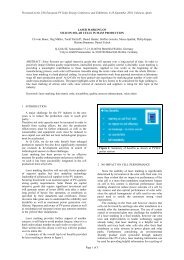
A NEW STANDARD FOR HOLISTIC QUALITY ASSURANCE<br />
B. Jaeckel 1 , A. Krtschil 1 , D. Cunningham 2 , N. Forney 2 , C. LaMothe 2 , A. Nguyen 2 , M. Disser 3 and A. Roth 3<br />
1 Q-<strong>Cells</strong> SE, Bitterfeld-Wolfen, Germany<br />
2 BP Solar International Inc., Frederick, Maryland, USA<br />
3 VDE Testing and Certification Institute, Offenbach, Germany<br />
ABSTRACT: In this paper we present a <strong>new</strong> <strong>standard</strong> <strong>for</strong> product <strong>quality</strong> validation with special emphasis<br />
on reliability and mass production monitoring to implement a better level of product <strong>quality</strong> and of better<br />
customer and investor confidence in the products. This <strong>new</strong> <strong>quality</strong> <strong>standard</strong> will be expressed by a <strong>new</strong><br />
<strong>quality</strong> label: VDE Quality-Tested. The seal and the related criteria set a much higher technical <strong>quality</strong><br />
<strong>standard</strong> as it is currently found in industry. It contains three major improvements compared to <strong>standard</strong><br />
product certification and surveillance. First, we defined harder product qualification criteria, e.g. longer<br />
testing times combined with stricter pass/fail criteria to provide longer reliability of the modules in the field.<br />
Second, several inline tests like wet-leakage and high-pot-tests were implemented in mass production as<br />
well as a 100% product control by electroluminescence. Most of these tests are not required by <strong>standard</strong><br />
module qualification and production surveillance, but appearing fails are suspected to have significant<br />
impact on module safety and system per<strong>for</strong>mance. In consequence, these additional tests will directly<br />
increase the confidence level of investors and costumers. Third pillar of the Quality-Tested seal is a<br />
quarterly monitoring of modules reliability by means of regular climate chamber tests with focus on thermomechanical<br />
and humidity-temperature-induced stresses.<br />
In summary, Q-<strong>Cells</strong>, BP Solar and VDE Testing and Certification Institute present a <strong>new</strong> <strong>quality</strong> <strong>standard</strong><br />
on base of harder criteria within initial module qualification and permanent production monitoring, which<br />
gives direct value-add <strong>for</strong> customers in terms of better module reliability, safety and bankability <strong>for</strong> PV<br />
investments.<br />
Keywords: Qualification and Testing, Stability, PV Module, Crystalline Silicon, c-Si, Safety, Quality<br />
insurance, Reliability, Durability<br />
1 INTRODUCTION<br />
In recent years a systematic change in PV could be<br />
observed. Started decades ago when “green<br />
alternatives” to produce electrical power, due to the<br />
feed-in- tariffs PV is more and more regarded as<br />
pure investment. There<strong>for</strong>e it has been getting more<br />
important to prove the reliability of a PV product.<br />
Investors, banks and consultants are asking <strong>for</strong><br />
certificates and other documents to demonstrate the<br />
<strong>quality</strong>, durability and reliability of a PV product, and<br />
in consequence to minimize investment risk.<br />
In photovoltaics one of the major parts regarding<br />
reliability is usually the PV module itself. Very often<br />
failures occur on system level e.g. failing of the<br />
inverter or fuses. But the <strong>quality</strong> of the PV modules<br />
is a crucial factor <strong>for</strong> systems per<strong>for</strong>mance and<br />
long-term reliability. To further improve the modules<br />
<strong>quality</strong> it is very important to develop testing<br />
procedures that are adequate <strong>for</strong> today’s products<br />
evaluations. With this approach in mind Q-<strong>Cells</strong>, BP<br />
Solar and VDE started in 2010 to develop the <strong>new</strong><br />
VDE Quality-Tested sequence. Herein the focus is<br />
set on a high confidence level in the initial<br />
certification of the product as well as on monitoring<br />
approaches <strong>for</strong> the mass production to provide more<br />
confidence to consumers and investors that they<br />
only get modules with very high <strong>quality</strong>, low power<br />
degradation and high safety <strong>standard</strong>s.<br />
2 BACKGROUND OF VDE-QUALITY-TESTED<br />
SEAL<br />
The background of the VDE-Quality-Tested seal is<br />
best described on the VDE-webpage:<br />
(http://www.vde.com/en/Institute/Portfolio/Usability%<br />
20Test/Pages/VDEQualityTested.aspx).<br />
“The details <strong>for</strong> this usability-seal are as following:<br />
Products enjoy a high degree of acceptance among<br />
consumers and obviously offer substantial benefits<br />
to manufacturers and retailers. It is a well-known<br />
fact that consumers prefer products bearing a<br />
reliable <strong>quality</strong> label.<br />
VDE tested products are safe and greatly trusted by<br />
consumers. Moreover, consumers expect the<br />
products they buy to be suitable <strong>for</strong> use and<br />
manufactured to a high <strong>standard</strong> of <strong>quality</strong>. The<br />
VDE institute has responded to these demands and<br />
added test <strong>for</strong> suitability of use to its range of<br />
services offered…<br />
Quality Tested is the VDE Certification Mark <strong>for</strong> the<br />
suitability of electro technical products <strong>for</strong> use… We<br />
tested the <strong>quality</strong> characteristics of each product<br />
based on the relevant rules, laws, norms and<br />
special <strong>standard</strong>s. In addition to the legally<br />
stipulated requirements (safety, EMV, health<br />
protection), our evaluation also takes into<br />
consideration the technical findings of the VDE<br />
experts and the expertise of the VDE Institute<br />
gathered from surveys, which are ultimately<br />
reflected in the setting of the <strong>standard</strong>s, as well as<br />
any predictable abnormal use.<br />
VDE Quality Tested: Playing it safe - If you are<br />
involved in manufacturing or retailing, you can play<br />
it safe with the mark VDE Quality Tested. The<br />
outstanding competence of the VDE in the field of<br />
safety is the firm foundation on which to base the<br />
combination with suitability <strong>for</strong> use testing. . . .<br />
Products bearing the VDE Quality Mark there<strong>for</strong>e<br />
guarantee a high level of <strong>quality</strong>. What is so special
Preprint to be published in the proceedings of the<br />
26 th European Photovoltaic Solar Energy Conference, 5–9 September 2011, Hamburg, Germany<br />
about it: The ID Number: With the help of the ID<br />
Number assigned to the relevant product you can<br />
learn more about additional aspects of the product<br />
characteristics that have<br />
been tested (see Figure 1).<br />
This offers two major advantages:<br />
• Helping the consumer when deciding which<br />
product to buy<br />
• Improved transparency when deciding<br />
which product to buy<br />
Access to the relevant product data sheet can be<br />
found at www.vde.com/certificate. Enter the<br />
number and you will be provided with in<strong>for</strong>mation<br />
you seek. Try it out by entering the ID Number<br />
49000000 in the search box on the relevant web<br />
page.”<br />
3 TEST SEQUENCES AND REASONS FOR<br />
IMPLEMENTING THE SELECTED TESTING<br />
PROCEDURES<br />
This <strong>new</strong> <strong>quality</strong> label is the result of collaboration<br />
between Q-<strong>Cells</strong>, BP Solar and VDE Testing and<br />
Certification Institute and includes innovative testing<br />
methods <strong>for</strong> module design and increased sampling<br />
of modules <strong>for</strong> verification of <strong>quality</strong> during the<br />
different stages of manufacturing process. It covers<br />
the entire value chain of module production,<br />
including a<br />
• harder module design and safety<br />
qualification<br />
• continuous mass production inline <strong>quality</strong><br />
monitoring<br />
• continuous offline site work monitoring.<br />
The following paragraphs will present the ideas<br />
behind the modifications and why an accelerated<br />
aging test sequence was developed <strong>for</strong> routine<br />
testing.<br />
3.1 Initial certification<br />
To qualify <strong>for</strong> the VDE Quality-Tested seal an initial<br />
certification following Figure 2 must be per<strong>for</strong>med.<br />
The major differences compared to IEC 61215 [1]<br />
and 61730-2 [3] are, that the number of testsamples<br />
were doubled, the testing periods were<br />
increased to a damp-heat test of 1500h and a<br />
thermal-cycling test of 400 cycles is per<strong>for</strong>med. The<br />
increase of testing time was based on scientific<br />
studies. These have shown that failure modes<br />
involving a high power loss starting typically to be<br />
detectable in the range of 1200 to 1500h under<br />
damp-heat (85°C / 85% relative humidity)<br />
conditions. There are plenty failure modes which we<br />
won’t describe in detail, since in here it is more<br />
important to detect those failures as soon as<br />
possible and as high efficient as possible.<br />
As the examples in Figure 3 on the left part show,<br />
four modules would pass the IEC criteria, but only<br />
one (sample 4) the <strong>new</strong> harder criteria after 1500h.<br />
The right part of Figure 3 shows some example data<br />
from thermal cycling tests with the corresponding<br />
IEC and Quality-tested pass/fail requirements.<br />
Although all modules would pass the tests the<br />
knowledge of power loss data after 300 to 400<br />
cycles is helpful to understand the long term<br />
behavior of the modules. Sample 1 obviously<br />
stabilizes at around 2% power loss whereas sample<br />
3 displays a further decrease in power.<br />
In addition to the increased testing times a<br />
dynamical load test was inserted into the UV-TC-HF<br />
sequence. The test is per<strong>for</strong>med after the UV<br />
preconditioning test with a load of 1000Pa <strong>for</strong> 1000<br />
cycles. The aim of the dynamical mechanical load<br />
test is to show that the module will survive a high<br />
number of load cycles, typically induced by<br />
continuous wind blowing and wind gusts. This<br />
periodical stress on the module will impact the<br />
failure rate of PV-modules caused, e.g., by broken<br />
soldering points or cracked cells [4, 5]. To see the<br />
influence of these induced defects on the long term<br />
reliability the dynamical load test was inserted<br />
be<strong>for</strong>e the TC-50 and HF-10 tests.<br />
On top of that the pass/fail criteria <strong>for</strong> the modules<br />
per<strong>for</strong>mance were tightened up. Instead of the<br />
usually allowed 8% power loss [1] a VDE Quality-<br />
Tested module is only allowed to have a total power<br />
loss of 5%. These changes will dramatically<br />
increase the confidence that a certain module<br />
design will fulfill the requirements <strong>for</strong> the usually<br />
long warranty periods used in photovoltaics.<br />
3.2 Inline control:<br />
The initial certification is only the first step towards<br />
the <strong>new</strong> seal. There are several requirements <strong>for</strong><br />
inline and offline testing. For a normal certificate,<br />
that is a combination of IEC 61215 [1] und IEC<br />
61730 [2, 3], VDE already specifies several inline<br />
tests in the PM 434 [6] document in which the<br />
requirements <strong>for</strong> 100% power measurement and<br />
100% high-pot-test are described. On top of that the<br />
<strong>new</strong> additional criteria <strong>for</strong> Quality-Tested modules<br />
are:<br />
• 100% Electroluminescence (EL)<br />
• 1% wet-leakage-test of mass production<br />
• a reverse-current overload-test per day<br />
• and a grounding-test per day<br />
The number of samples per day <strong>for</strong> the reversecurrent<br />
overload test and the grounding test are<br />
normalized to a production capacity of 1 mio.<br />
modules per year. If more modules are produced<br />
more samples have to be tested.<br />
These additional tests will provide a fast way to<br />
collect data about the produced products related to<br />
their long term reliability. Electroluminescence is a<br />
powerful tool to investigate cracks and other defects<br />
of the module on cell level. For a Quality-Tested<br />
module only a certain number and kinds of defects<br />
are allowed. The definition of these defects is part of<br />
the Quality-Tested definition from VDE and is based<br />
on internal studies and on literature [7–9]. The<br />
allowed number of defects depends on the number<br />
of cells in a module. In the basic document the<br />
numbers are related to a <strong>standard</strong> 60-cell module.<br />
The allowed number of defects of a different cell<br />
combination in a module can be linearly<br />
extrapolated. By restricting the number of defects<br />
the reliability of a product will increase.<br />
In a similar way the reverse-current overload test is<br />
used. By using an Infra-Red (IR) camera instead of<br />
a cheese cloth it is possible to observe local hotspots<br />
(IR-imaging). An example with the
Preprint to be published in the proceedings of the<br />
26 th European Photovoltaic Solar Energy Conference, 5–9 September 2011, Hamburg, Germany<br />
corresponding EL-picture is shown in Figure 4.<br />
Locally increased cell temperatures might be<br />
caused by a localized higher resistivity, but possibly<br />
also by missing soldering points (see circles in<br />
Figure 4). Those missing soldering points will<br />
increase the current density on the other ribbon(s).<br />
This can increase the risk of material failure and<br />
might lead to e.g. arcing. There<strong>for</strong>e IR-imaging can<br />
be used to look <strong>for</strong> bad soldering and is<br />
complementary to electroluminescence. Similar<br />
images can also be found in literature where the<br />
method is used in the same way [10, 11].<br />
Since grounding is not mandatory in most countries<br />
there is no need <strong>for</strong> testing the ground continuity of<br />
the PV-modules frame. But <strong>for</strong> recent failures, e.g.<br />
by potential induced degradation [12, 13], a simple<br />
solution might be to ground the modules properly.<br />
To establish a safe grounding path from each part of<br />
the frame the implementation of the ground<br />
continuity test will help to increase module safety,<br />
usability and reliability.<br />
3.3 Quarterly <strong>quality</strong> monitoring<br />
The third part of the VDE-Quality-Tested seal is a<br />
quarterly monitoring of modules. In this monitoring<br />
several modules were tested using accelerated<br />
aging techniques. The full scheme of the quarterly<br />
testing requirements is shown in Figure 5.<br />
To ease the process but not to reduce the<br />
in<strong>for</strong>mation <strong>quality</strong>, one shipping container is<br />
randomly selected from production. Nowadays a<br />
container typically holds around twenty modules.<br />
There<strong>for</strong>e the start <strong>for</strong> the inspection is an amount<br />
of those twenty modules. They are checked<br />
according to the optical sorting criteria (OSC)<br />
defined by clause 7 in IEC 61215, followed by a<br />
power measurement and an EL-check. This data<br />
can then be compared to the factory values. These<br />
will allow <strong>for</strong> checking the calibration of the factory<br />
flasher and the high-pot-station as well as the<br />
sorting in accordance with EL-criteria. These<br />
measurements also help to check the packaging<br />
and the transport of the modules.<br />
As it is shown in Figure 5, four modules were<br />
selected after the initial check <strong>for</strong> a reliability<br />
evaluation using accelerated aging techniques.<br />
These modules are first preconditioned to proof that<br />
labeling is in accordance with EN-50380 [14]. Then<br />
the scheme shows two parallel sequences: One is<br />
focusing on thermo-mechanical stress tests, the<br />
other on the impact of humidity and temperature.<br />
Thermo-mechanical stress test sequence: This<br />
sequence consists of three major tests. The<br />
sequence starts with a dynamical load test followed<br />
by a thermal cycling test with 100 cycles. The<br />
parameters <strong>for</strong> the dynamical load test are the same<br />
as <strong>for</strong> the basic certification. The two tests will<br />
induce cracks and weaken solder joints in a time<br />
period as short as possible. The use of 100 cycles is<br />
based on experience and with the requirement in<br />
mind, that the testing routine should also provide a<br />
fast feedback loop <strong>for</strong> production. The test<br />
sequence is finalized with a hot-spot test of one<br />
module as it is defined in IEC 61215. The<br />
combination of these tests will provide in a as short<br />
as possible time period the most details about the<br />
running production related to thermal and<br />
mechanical issues like cracking of cells or a high<br />
number of finger interrupts.<br />
Humidity and temperature stress test sequence:<br />
The second sequence starts with a reverse currentoverload<br />
test to check soldering homogeneity as<br />
well as any risk <strong>for</strong> hot-spotting, fire and durability of<br />
a module not to fail if there is something bad with<br />
the PV generator [15]. The<br />
test is per<strong>for</strong>med in accordance with IEC 61730-2,<br />
with the major difference that an IR-camera is used<br />
to detect temperature differences. After this first test<br />
both modules were exposed to damp-heat <strong>for</strong> 250h.<br />
Infant mortalities like detaching J-boxes or<br />
delamination due to bad materials will be<br />
detectable. The relatively short time will bring up the<br />
possibility to screen and monitor the production. To<br />
ensure the safety of the modules after any kind of<br />
aging the two consecutive tests were selected: First,<br />
the wiring compartment test from UL-1703 [16] to<br />
check the attachment of the J-Box and second, the<br />
ground continuity test from IEC 61730-2 to proof<br />
proper electrical frame connections.<br />
For all the above discussed tests a total power loss<br />
pass/fail criteria of 5% is defined. For the safetytests<br />
the pass/fail values from IEC 61215 and IEC<br />
61730 apply.<br />
3.4. Changes on a module the Quality-<br />
Tested seal - retesting requirements<br />
To re-qualify a changed module type the retesting<br />
guidelines from IEC apply with some differences:<br />
First, the adjusted testing times and sequences<br />
have to be used as shown in scheme in Fig. 1 and<br />
second, the harder pass/fail criteria of 5% applies.<br />
4 CONCLUSION<br />
In order to increase the high <strong>quality</strong> <strong>standard</strong> <strong>for</strong> PV<br />
modules it is necessary to adopt knowledge from<br />
field and laboratories in <strong>new</strong> <strong>standard</strong>s. It is also<br />
important to regularly prove the <strong>quality</strong> of a product<br />
to customers, investors and banks. The concept<br />
behind the VDE-<strong>quality</strong>-tested seal <strong>for</strong> PV combines<br />
harder qualification criteria as well as continuous<br />
production and laboratory data to increase trust,<br />
bankability and investment <strong>assurance</strong> of a product<br />
labeled with the <strong>new</strong> seal. In this paper the ideas<br />
behind the seal and the selection of the tests are<br />
described and motivated <strong>for</strong> a broader<br />
understanding. In summary the seal consists of<br />
three major parts: First the initial qualification,<br />
second the inline testing done on a statistically<br />
reliable sample size, and third a quarterly testing<br />
sequence to control the long term reliability of the<br />
modules. Due to the proven high <strong>quality</strong>, durability<br />
and reliability of the product the risk of an<br />
investment is strongly reduced and projects with<br />
these products are more bankable.<br />
5 LITERATURE<br />
[1] IEC 61215 Ed.2: Crystalline silicon terrestrial<br />
photovoltaic (PV) modules - Design qualification and<br />
type approval (2005)
Preprint to be published in the proceedings of the<br />
26 th European Photovoltaic Solar Energy Conference, 5–9 September 2011, Hamburg, Germany<br />
[2] IEC 61730-1 Ed.1: Photovoltaic (PV) module<br />
safety qualification - Part 1: Requirements <strong>for</strong><br />
construction (2004)<br />
[16] UL 1703-3 Ed.1, Flat-Plate Photovoltaic<br />
Modules and Panels (2004)<br />
[3] IEC 61730-2 Ed.1: Photovoltaic (PV) module<br />
safety qualification - Part 2: Requirements <strong>for</strong><br />
testing (2004)<br />
[4] M. Assmus, S. Jack, K.-A.Weiss, M. Koehl:<br />
Measurement and simulation of vibrations of PVmodules<br />
induced by dynamic mechanical loads;<br />
Progress in Photovoltaics: Research and<br />
Applications (2011)<br />
[5] S. Koch, J. Kupke, D. Tornow, M. Schoppa, S.<br />
Krauter, P. Grunow: Dynamic Mechanical Load<br />
Tests on Crystalline Silicon Modules; 25th European<br />
Photovoltaic Solar Energy Conference – Valencia<br />
(2010)<br />
[6] VDE PM-434: Test instruction <strong>for</strong> factory<br />
surveillance of terrestrial photovoltaic modules in<br />
accordance with VDE 0126-30-1, -30-2, -31, -32<br />
(2010)<br />
[7] M. Koentges, K. Bothe:<br />
Elektrolumineszenzmessung an PV-Modulen,<br />
Photovoltaik aktuell (2008)<br />
[8] M. Koentges, I. Kunze, S. Kajari-Schroeder, X.<br />
Breitenmoser, B. Bjorneklett: Quantifying the risk of<br />
power loss in PV modules due to micro cracks, 25th<br />
European Photovoltaic Solar Energy Conference,<br />
Valencia, Spain (2010)<br />
[9] U. Hoyer, C. Bürhop, U. Jahn:<br />
Electroluminescence and Infrared Imaging <strong>for</strong><br />
Quality Improvements of PV Modules, 23rd<br />
European Photovoltaic Solar Energy Conference<br />
(2008)<br />
[10] J. H. Wohlgemuth, D.W. Cunningham, P.<br />
Monus, J. Miller, A. Nguyen: Long term reliability of<br />
Photovoltaic modules; Conference Record of the<br />
2006 IEEE 4th World Conference on Photovoltaic<br />
Energy Conversion (2006)<br />
[11] M. Koehl: Schlussbericht - Zuverlässigkeit von<br />
PV-Modulen; Fraunhofer ISE Reports (2009)<br />
[12] J. Siemer: Hohes Schadenspotential, Photon<br />
(12/2010)<br />
[13] P. Hacke, K. Terwilliger, R. Smith, S. Glick, J.<br />
Pankow, M. Kempe, S. Kurtz, I. Bennett, M. Kloos:<br />
System voltage potential-induced degradation<br />
mechanisms in PV Modules and Methods <strong>for</strong> Test,<br />
37st IEEE Photovoltaic Specialists Conference -<br />
Seattle (2011)<br />
[14] EN-50380: Datasheet and Label requirements<br />
<strong>for</strong> photovoltaic modules (2003)<br />
[15] P. Futan: Fehlerströme und Schutztechniken in<br />
Photovoltaikanlagen, 3. Sicherungstag -Würzburg<br />
(2010)
Preprint to be published in the proceedings of the<br />
26 th European Photovoltaic Solar Energy Conference, 5–9 September 2011, Hamburg, Germany<br />
Figure 1: VDE Quality-Tested seal<br />
Figure 2: Full scheme <strong>for</strong> the design qualification process <strong>for</strong> a VDE-Quality-Tested module.
Preprint to be published in the proceedings of the<br />
26 th European Photovoltaic Solar Energy Conference, 5–9 September 2011, Hamburg, Germany<br />
Figure 3: Results from damp-heat (left) and thermal cycling test (right) that clearly show that critical power loss<br />
often occurs between 1200 and 1500h of damp-heat. The increased number of cycles from 200 cycles to 400<br />
cycles in the thermal cycling test will additionally improve confidence to the selected module design.<br />
Figure 4: Example of EL (left) and IR-pictures (right) to show the effect of soldering problems that can be<br />
detected by IR-imaging. The correlation is quite obvious.
Preprint to be published in the proceedings of the<br />
26 th European Photovoltaic Solar Energy Conference, 5–9 September 2011, Hamburg, Germany<br />
Figure 5: Scheme <strong>for</strong> the monthly <strong>quality</strong> check. All "intermediate measurements" are defined as a<br />
measurement of power, high-pot, wet-leakage-test and electroluminescence as well as a visual inspection of the<br />
modules.