service guide 4corrosive air unit - Purafil
service guide 4corrosive air unit - Purafil
service guide 4corrosive air unit - Purafil

Create successful ePaper yourself
Turn your PDF publications into a flip-book with our unique Google optimized e-Paper software.
www.purafil.com<br />
FIRST<br />
IN CLEAN<br />
AIR<br />
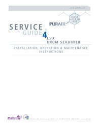
SERVICE<br />
GUIDE 4 CORROSIVE AIR UNIT<br />
INSTALLATION, OPERATION & MAINTENANCE<br />
INSTRUCTIONS<br />
TO BE USED IN CONJUNCTION WITH:<br />
SERVICE GUIDE 4 Gage Unit<br />
SERVICE GUIDE 4 Blower Assembly<br />
2654 Weaver Way Doraville, Georgia, 30340, U.S.A. tel: (770) 662-8545 (800)-222-6367 www.purafil.com<br />
© <strong>Purafil</strong> 2006 SrvcGde - CA - 01
TABLE OF CONTENTS<br />
1.0 PRE-INSTALLATION INSTRUCTIONS<br />
1.1 SAFETY CONSIDERATIONS<br />
1.2 RECEIVING INSTRUCTIONS<br />
1.3 INSPECTION<br />
1.4 STORAGE<br />
1.5 FOUNDATIONS AND CLEARANCES<br />
2.0 OPERATIONAL CONCEPTS AND DETAILS<br />
2.1 C.A. APPLICATIONS<br />
2.2 HOW PURAFIL ® SYSTEMS WORK<br />
2.3 BASIC DESIGN OF THE C.A.<br />
2.4 C.A. OPTIONS / DEFINITIONS<br />
3.0 INSTALLATION<br />
3.1 POSITIONING THE UNIT<br />
3.2 MODULES<br />
3.3 PARTICULATE FILTERS<br />
3.4 GAGE UNIT<br />
3.5 POST-START INSPECTION/CHECK<br />
4.0 MAINTENANCE<br />
4.1 REPLACEMENT PARTS AND MATERIALS<br />
4.2 SPECIAL PRECAUTIONS<br />
4.3 PURAFIL ® STAIN REMOVAL<br />
5.0 WARRANTY INFORMATION<br />
6.0 TROUBLE SHOOTING<br />
7.0 SAMPLING RECORD<br />
LIST OF FIGURES<br />
FIGURE<br />
TITLE<br />
1 UNIT SCHEMATIC<br />
2 REMOVAL OF VERTICAL UNIT WITH CASTERS<br />
3 MODULE DIRECTION FOR VERTICAL UNIT<br />
4 MODULE DIRECTION FOR HORIZONTAL UNIT<br />
5 MODULE LABEL<br />
6 GAGE UNIT CONNECTIONS<br />
7 FAN ROTATION DIRECTION<br />
8 DATA SHEET
1.0 PRE-INSTALLATION INSTRUCTIONS<br />
1.1 SAFETY CONSIDERATIONS<br />
• Read this Service Manual carefully. Be thoroughly familiar with the controls and<br />
the proper use of the equipment.<br />
• This manual should be retained with the <strong>unit</strong> because it contains the information<br />
necessary for proper maintenance. There is a pocket envelope provided for this<br />
purpose. Attach it permanently to the <strong>unit</strong>.<br />
• Keep all nuts, bolts, and screws tight to be sure the equipment is in safe<br />
working condition.<br />
CAUTION:<br />
• Installer should be a trained, experienced <strong>service</strong> person.<br />
• Disconnect power supply before wiring connections are made to prevent<br />
possible electrical shock or damage to equipment.<br />
• Check the assembly and component weights to be sure that the rigging<br />
equipment can handle them safely.<br />
• Be sure that the <strong>unit</strong> is balanced well in the transporting device.<br />
• Never pressurize the equipment in excess of specified test pressure.<br />
• Always conduct a thorough check when the installation is complete.<br />
• Never enter an enclosed blower cabinet or reach into a housing while fan is<br />
running.<br />
• The motors in PURAFIL ® equipment get very hot. This is normal and should not<br />
be regarded as a problem with the motor. However, take special care to avoid<br />
touching the hot areas.<br />
1.2 RECEIVING INSTRUCTIONS<br />
Systems are normally shipped assembled and with motors mounted. All<br />
<strong>unit</strong>s are attached securely to skids. It is recommended that <strong>unit</strong>s be left on their<br />
skids for protection and ease of handling while transporting. Straps, rigging,<br />
slings, or hooks attached to the skids may be used, with proper care. The <strong>unit</strong>s<br />
are well protected with triple wall board and are secured with metal bands.<br />
Forklifts may be used under the skids, but exercise caution to prevent damage.
Upon receiving systems from <strong>Purafil</strong>, Inc., note any shipping damage, obvious or<br />
hidden, to your carrier and on your Bill of Lading. All problems should be<br />
handled between the customer and carrier except for U.P.S. shipments, which<br />
require the customer to contact <strong>Purafil</strong>, Inc. for action.<br />
• If the <strong>unit</strong> is to be stored before use, see Section 1.4 in this manual.<br />
• If the <strong>unit</strong> is to be installed immediately, be sure to check Section 1.5 in this<br />
manual.<br />
• To uncrate <strong>unit</strong>, cut metal bands and remove packaging.<br />
• For positioning and special handling, see Section 3.1 in this manual.<br />
1.3 INSPECTION<br />
The condition of the <strong>unit</strong> upon its arrival is critical to its proper operation. Prior<br />
to start-up, inspect the <strong>unit</strong> carefully, according to the checklist below. Correct<br />
any inadequacies before start-up to prevent possible damage or inefficiency.<br />
Note, should there be any questions concerning the <strong>unit</strong>, refer to the numbers<br />
found on the <strong>unit</strong> identification plate, when contacting the PURAFIL ®<br />
representative.<br />
PRE-OPERATION CHECK LIST<br />
YES NO CONDITION<br />
____ ____ 1. Configuration and material are as specified on the<br />
sales order form<br />
____ ____ 2. Measurements fit submittal requirements<br />
____ ____ 3. Parts are all present including modules, particulate<br />
filters, media, and gage <strong>unit</strong>s<br />
____ ____ 4. Motor phase and voltage are correct<br />
____ ____ 5. Modules, prefilter, and final filter all fit properly<br />
____ ____ 6. Latches hold securely and gaskets seal properly<br />
____ ____ 7. Labels and serial numbers are present<br />
____ ____ 8. Airflow direction is consistent with installation<br />
requirements (check labels attached to <strong>unit</strong>)
Note: Checking specific points is also imperative after the <strong>unit</strong> is started up. See<br />
section 3.5 in this manual for checklist.<br />
1.4 STORAGE<br />
The <strong>unit</strong> should be protected from the elements during storage, especially when<br />
storage time is extensive. While indoor storage is considered best, outdoor<br />
storage can be adequate when precautions are taken.<br />
OUTDOOR STORAGE PRECAUTIONS<br />
• Cover the equipment with a tarp making sure that the bearings in the<br />
blower/motor assembly are well covered and properly ventilated, to prevent<br />
moisture condensation. Intake and discharge openings must be well covered.<br />
(Use of black plastic as a cover may cause excessive condensation and rusting.)<br />
• If there is the possibility of moisture collection, allow for proper drainage.<br />
INDOOR AND OUTDOOR STORAGE PRECAUTIONS<br />
• If the <strong>unit</strong> is to be stored for an extended period of time (4-6 months or more),<br />
remove the belt from the sheaves to prevent unnecessary deformation of belting<br />
material (see Section 4.4 in this manual); rotate fans monthly to prevent bearing<br />
damage.<br />
• If motor starter is purchased with the <strong>unit</strong> (optional) and it is to be stored with<br />
the <strong>unit</strong>, be sure to read instructions enclosed on the starter kit to prevent<br />
problems due to storage.<br />
• Do not place heavy equipment on top of the <strong>unit</strong>.<br />
• Store PURAFIL ® media in a dry place with less than 95% relative humidity.<br />
1.5 FOUNDATION AND CLEARANCES<br />
FOUNDATIONS<br />
Some <strong>unit</strong>s may require new or reinforced foundations, due to their weight.<br />
Always be sure to check that the existing foundation is adequate for the <strong>unit</strong> to<br />
be installed. Units to be used indoors require particular attention to strength of<br />
foundation. In some instances, a concrete base is best suited to the system.<br />
Concrete lessens the chance for vibration than if metal structures are used.
CLEARANCE<br />
All <strong>unit</strong>s should be easily accessible for the required periodic maintenance. Do<br />
not block return and discharge grilles. Sufficient minimum clearances can be<br />
recommended by the local PURAFIL ® representative.<br />
2.0 OPERATIONAL CONCEPTS & DETAILS<br />
2.1 C.A. APPLICATIONS<br />
The Corrosive-Air Unit, or C.A. <strong>unit</strong>, is an <strong>air</strong> purification system which<br />
incorporates gas and particulate cleansing equipment and an integral blower<br />
section. The system is designed for the protection of electronic and electrical<br />
equipment in control rooms, computer centers, motor control centers, operator<br />
consoles, crane cabs, etc., where the environment is contaminated by corrosive<br />
gases and fumes.<br />
2.2 HOW PURAFIL ® SYSTEMS WORK<br />
PURAFIL ® corrosion control systems normally utilize two types of <strong>air</strong> cleaning<br />
<strong>unit</strong>s to accomplish the <strong>air</strong> quality level necessary to preclude corrosion. While<br />
the P.P.U. scrubs outside <strong>air</strong> and acts as a sacrifice and surge control filter. The<br />
second type of <strong>unit</strong>, the Corrosive-Air (C.A.), cleans recycled <strong>air</strong>. The mixed <strong>air</strong><br />
cleaner bank design insures rapid decay of peak concentrations, and reduces the<br />
level of contamination in the room to normal; maximum operating levels. The<br />
dual system is thus capable of contaminant removal efficiencies of well above<br />
99%. The P.P.U. can of course operate exclusive of the C.A. <strong>unit</strong>, when the<br />
room <strong>air</strong> must be exhausted, and it is called the Stand-Alone P.P.U. in this type of<br />
application. Otherwise, the P.P.U. is ducted directly to the C.A. <strong>unit</strong>.<br />
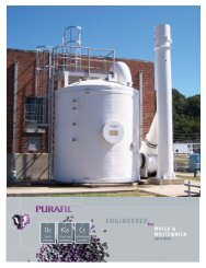
2.3 BASIC DESIGN OF THE C.A.<br />
The C.A. <strong>unit</strong> is self contained having particulate and gaseous contamination<br />
control capabilities. Powered with an industrial, aluminum plug blower, the C.A.<br />
<strong>unit</strong> has continuous seam welded construction and a 14 gauge steel housing.<br />
The <strong>unit</strong> is available in several horizontal and vertical configurations. The<br />
horizontal model is designed for ceiling mounting or integration into existing<br />
ductwork, while the vertical free-standing model is designed for floor location.
FIGURE 1: UNIT SCHEMATIC<br />
The C.A. includes one or more of the following sequential components, which<br />
correspond to the numbers in Figure 1:<br />
1. PREFILTER—as the <strong>air</strong> enters the next section, it passes through a medium<br />
efficiency (30%), particulate filter. The filter collects atmospheric dust and<br />
larger particles, thereby preventing clogging of the perforated surfaces and<br />
pellet surface pores in the next stage of the <strong>unit</strong>.<br />
2. PURAFIL ® MODULES--the <strong>air</strong> passes through perforated, polystyrene, “V”<br />
shaped modules, which contain PURAFIL ® media, which is required when the<br />
environment is laden with heavy hydrocarbons and/or chlorine compounds.<br />
3. BLOWER--the <strong>air</strong> is then propelled further by the blower assembly, which<br />
includes a TEFC Direct Drive and <strong>air</strong>foil wheel, assuring even, quiet <strong>air</strong>flow.<br />
4. FINAL FILTER—before exiting the <strong>unit</strong>, the <strong>air</strong> moves through an ultra-high<br />
efficiency (90%) rigid-type, final filter. Any remaining contaminants, such as<br />
media dust and <strong>air</strong>borne contaminants are removed in this stage.
5. GAGE UNIT(S)--although not a physical part of the <strong>unit</strong> cabinet, the gage<br />
<strong>unit</strong>s are an integral part of the C.A.’s proper operation. These magnehelic<br />
gages are connected directly to specific pressure taps (See Gage Unit Service<br />
Guide).<br />
2.4 C.A. OPTIONS / DEFINITIONS<br />
Optional equipment is available to accommodate varying customer needs. These<br />
(options) may or may not be included with your <strong>unit</strong>, and are not addressed<br />
specifically in this manual. Contact the local PURAFIL ® representative for further<br />
information.<br />
• Motor starter package—includes NEMA 3R type enclosure, magnetic motor<br />
starter, and accessories<br />
• Single phase motor<br />
• Weatherproofing 1 (horizontal <strong>unit</strong> only)<br />
• Insulation (horizontal <strong>unit</strong> only)<br />
• Reverse <strong>air</strong>flow<br />
• Tap holes for gages located on the side opposite of the door<br />
• Casters (vertical <strong>unit</strong> only)<br />
• Specific media as manufactured by <strong>Purafil</strong>, Inc.<br />
Weatherproofing consists of a cross broken pan on top of the <strong>unit</strong> to shed<br />
water, with drip edges turned out over the doors to prevent direct<br />
impingement of rain on the top edge of the doors. Any screws or bolts<br />
exposed on the exterior top or sides of the <strong>unit</strong> are gasketed.<br />
3.0 INSTALLATION<br />
After the entire pre-operative inspection is finished (Section 1.3), complete the<br />
following sequence for installation by referring to the instructions in Section 3.1 -<br />
3.5:<br />
(1) Remove the <strong>unit</strong> from the skid and position it in the designated operation<br />
location.<br />
(2) Hook up the electrical connections and check for proper rotation.<br />
(3) Fill and install the modules.<br />
(4) Install the particulate filter. (See section 3.3).<br />
(5) Install and check the gage <strong>unit</strong>s (See Gage Unit Service Guide).<br />
(6) Start the <strong>unit</strong>.<br />
(7) Perform post-start inspection check. (See Section 3.5)<br />
3.1 POSITIONING THE UNIT<br />
Review Section 1.5 in this manual for foundation and clearance instructions. The<br />
standard <strong>unit</strong> can simply be lifted from its skid and "walked" or transported by<br />
lift to its pre-designated operation location (if in close proximity to the skid),<br />
according to facility safety requirements. If the <strong>unit</strong> has casters (optional),<br />
remove it from the skid according to the following instructions and Figure 2:
FIGURE 2: REMOVAL OF VERTICAL UNIT WITH CASTERS FROM SKID<br />
The <strong>unit</strong> is shipped lying horizontally on a skid. The <strong>unit</strong> has been arranged on<br />
the skid so that the <strong>unit</strong> can be rocked upwards on the skid edge, allowing the<br />
wheels closest to the skid to be off the floor while settling the wheels farthest<br />
from the skid on the floor. At this point, it is only necessary to remove the skid<br />
from the side of the <strong>unit</strong> and ease the second set of wheels to the floor. Note, it<br />
is suggested that you brace the wheels on the floor while easing the other<br />
wheels to the floor.<br />
3.2 MODULES<br />
Proper filling, installation, and maintenance of the chemical filtration media is<br />
critical to the <strong>unit</strong>’s efficient operation. The modules are designed specifically for<br />
media manufactured by <strong>Purafil</strong>, Inc. and allow the media to perform to its<br />
maximum efficiency, through proper shape and bed depth.<br />
FIGURE 3: MODULE DIRECTION FOR VERTICAL UNIT
FIGURE 4: MODULE DIRECTION FOR HORIZONTAL UNIT<br />
FIGURE 5: MODULE LABEL<br />
3.3 PARTICULATE FILTERS<br />
Proper selection and installation of particulate filters for use in PURAFIL ® systems<br />
are necessary steps in obtaining the <strong>air</strong> quality best suited to the user’s needs.<br />
Particulate filters are available in different sizes and efficiencies, and variations in<br />
either of these characteristics may affect the efficiency of the PURAFIL ® system.<br />
Consult filter information found in the Data Sheet of this manual for further data<br />
and projected replacement date.<br />
TP-25 PREFILTER<br />
Install this filter by sliding it along the track so that <strong>air</strong>flow moves through the<br />
coarse white side first.<br />
JFL-90 FINAL FILTER<br />
Slide the 1" header into the provided track.<br />
3.4 GAGE UNIT<br />
The C.A. <strong>unit</strong> is supplied with a gage <strong>unit</strong>, which houses two magnehelic gages.<br />
Their purpose is to read pressure drop across particulate filters, thereby<br />
determining when to replace them, to insure consistency within the
ecommended <strong>guide</strong>line for <strong>air</strong>flow. As the particulate filters become soiled,<br />
pressure drop across them is increased, and the <strong>air</strong> volume actually moving<br />
through the system is decreased. Pressure drop is measured in terms of IWG.<br />
To insure consistency within the recommended <strong>guide</strong>lines for <strong>air</strong>flow, the<br />
particulate filters must be replaced when the appropriate terminal pressure drop<br />
is reached.<br />
Refer to the data sheet and the Gage Unit Service Guide for further information.<br />
FIGURE 6: GAGE UNIT CONNECTIONS
3.4 POST-START INSPECTION/CHECK<br />
Before initial start-up of system, contact your local PURAFIL ®<br />
Their name and phone number is attached to your system.<br />
representative.<br />
YES NO CONDITION<br />
____ ____ 1. Fan rotation is in the proper direction (See Blower<br />
Assembly Service Guide)<br />
____ ____ 2. Joints, seals, and gaskets do not leak.<br />
____ ____ 3. Gages work properly (i.e. lines hooked up correctly).<br />
____ ____ 4. Modules are completely full of media and fit<br />
properly.<br />
____ ____ 5. After 1-2 weeks of operation check belt(s) and<br />
tighten if necessary (See Blower Assembly Service<br />
Guide).<br />
FIGURE 7: FAN ROTATION<br />
4.0 MAINTENANCE<br />
4.1 REPLACEMENT PARTS AND MATERIALS<br />
While <strong>Purafil</strong>, Inc. products are built for durability, some parts of the PURAFIL ®<br />
<strong>unit</strong> will require replacement during the normal lifetime of the equipment.<br />
Replacement items may be ordered from your local PURAFIL ® representative or<br />
from <strong>Purafil</strong>, Inc.<br />
Certain moving parts such as motors, bearings and belts may also be obtained<br />
from conventional local sources. These items are divided into three categories.
Consumables: In order to maintain proper performance levels, particulate<br />
filters and PURAFIL ® media must be replaced periodically, as they have a finite<br />
life (See Media Sampling Procedure Service Guide).<br />
Gages: No lubrication or periodic servicing is required. The gage <strong>unit</strong> cover<br />
and housing should be kept clean, however, solvents are not recommended as<br />
a cleaning agent, as they will fog the cover. Occasionally disconnect pressure<br />
lines to vent both sides to the atmosphere; then re-zero (set) the gage (See<br />
Gage Unit Service Guide).<br />
Moving Parts: Bearings, sheaves, motors, belts, etc. are all subject to gradual<br />
deterioration and/or sudden breakdown (See Blower Assembly Service Guide).<br />
4.2 MEDIA REPLACEMENT<br />
PURAFIL ® engineered dry-chemical media has a finite life. Our media contains<br />
special active ingredients that react with odors and gaseous pollutants to<br />
remove them from the <strong>air</strong>stream. Once the active ingredients are spent, it is<br />
time to replace the media in your system. After start-up, your local PURAFIL ®<br />
representative will work with the owner to periodically secure media samples.<br />
<strong>Purafil</strong>, Inc. will provide regular laboratory analysis of such samples to establish<br />
life cycles. Note, color change of media does not indicate level of remaining<br />
life.<br />
Since every installation varies due to the type and quantity level of the<br />
contaminant, each operator must develop a sample schedule best suited to<br />
their system. However, until a schedule can be established, we recommend<br />
that a sample is taken from each vertical media bank and sent for analysis, so<br />
that a replacement date can be projected with a recommended sampling<br />
schedule.<br />
Media Life Analysis (MLA) is a complimentary <strong>Purafil</strong>, Inc. <strong>service</strong>. MLA Sample<br />
Kits are available through <strong>Purafil</strong>, Inc. If analysis reveals that it is time to replace<br />
the media, order the appropriate pounds of media required per module used<br />
in the <strong>unit</strong>. See Media Sampling Service Guide for instructions on how to take<br />
a media sample from your <strong>unit</strong>.<br />
4.3 PURAFIL ® STAIN REMOVAL<br />
The following stain removal procedure is stated here as information only, and<br />
neither <strong>Purafil</strong>, Inc., any of its subsidiaries, nor any agent or employee of <strong>Purafil</strong>,<br />
Inc. make any warranty or other representation regarding the efficacy or safety<br />
of this procedure. The stain removal could cause further damage to the<br />
garment or to the item from which one may attempt to remove the stain.<br />
If the dust from PURAFIL ® Chemisorbant, PURAFIL ® Select, or PURAFIL ® SP media<br />
comes in contact with organic material, there are two possible stain problems:
1. Manganese dioxide (MnO 2 ) which is insoluble, characterized by a medium<br />
brown color, and is found in expended PURAFIL ® media, can usually be<br />
removed by normal washing.<br />
2. New (unused) PURAFIL ® media contains potassium or sodium permanganate<br />
(KMnO 4 or NaMnO 4 ) which is a strong oxidant and will react with and<br />
discolor any organic material with which it comes in contact. These stains,<br />
which will be brownish black in color, may be removed using a solution of<br />
sodium bisulfite in water, after the garment has been removed from the<br />
person.<br />
However, if the fiber has been damaged by the permanganate, removal of<br />
the stain may make the damage more apparent.<br />
CAUTION: This procedure should start with a very weak solution, gradually<br />
increasing the strength until the stain is removed. Use of too strong a<br />
solution could conceivably cause additional fabric damage.<br />
NOTE: Sodium bisulfite gives off sulfur dioxide (SO 2 ) gas; therefore, it must<br />
be used in a well-ventilated area.<br />
5.0 SPECIAL PRECAUTIONS<br />
Disposal<br />
PURAFIL ® media is a non-toxic, non-flammable substance. Filtration of<br />
contaminants through PURAFIL ® media causes molecular changes to occur,<br />
and the resulting product is usually not harmful to the environment.<br />
Although special precautions are generally not required when disposing of<br />
spent media, government regulations may require specific disposal<br />
procedures if the resulting product could be harmful to the environment.<br />
Large quantities of PURAFIL ® media should not be disposed of in dumpsterlike<br />
equipment because the weight of the media could cause difficulties in<br />
handling the dumpster.<br />
Independent laboratory analysis for Environmental Protection Agency toxicity<br />
characteristics may be required if the contaminants eliminated from your<br />
environment include heavy metals and pesticides.<br />
Inhalation<br />
A well-ventilated work area is suggested for changing the PURAFIL ® media,<br />
as dusting occurs in fresh media due to handling abrasion. Workers should<br />
avoid direct inhalation of considerable PURAFIL® dust, as it induces sneezing.<br />
In closed, unventilated spaces, dust masks such as the 3-M No. 8500 are<br />
suggested.
Water<br />
Avoid exposing the PURAFIL ® media to water or precipitation, as this dissolves<br />
permanganate content. Storage of media should be in a dry place with less<br />
than 95% relative humidity. Exposure of permanganate solution to the skin<br />
causes brown staining which is temporary and not harmful. This staining can<br />
be removed by washing in a diluted solution of water and sodium bisulfite.<br />
Eye Contact<br />
If dust is exposed to the eyes or delicate membrane, flush thoroughly with<br />
water and seek treatment by a physician. Follow normal procedures for<br />
exposure to abrasive dust.<br />
*Additional information is provided in the <strong>Purafil</strong> Material Safety Data Sheet.<br />
7.0 WARRANTY INFORMATION<br />
PURAFIL ® warrants hardware equipment manufactured by PURAFIL ® to be free<br />
from defects in material and workmanship under normal use and <strong>service</strong> for<br />
twelve (12) months from startup date or eighteen (18) months from shipment<br />
date. PURAFIL'S obligation under this warranty shall be limited to replacing any<br />
parts thereof which shall be demonstrated to have been defective. THIS<br />
WARRANTY IS EXPRESSLY IN LIEU OF ALL OTHER WARRANTIES, EXPRESS OR<br />
IMPLIED, INCLUDING THE WARRANTIES OF MERCHANTABILITY AND FITNESS.<br />
PURAFIL MAKES NO WARRANTIES AS TO MERCHANTABILITY OR AS TO THE<br />
FITNESS OF THE MERCHANDISE FOR ANY PARTICULAR USE AND SHALL NOT BE<br />
LIABLE FOR ANY LOSS OR DAMAGE, DIRECTLY OR INDIRECTLY, ARISING FROM<br />
THE USE OF SUCH MERCHANDISE OR FOR CONSEQUENTIAL DAMAGES. No<br />
person, firm or corporation is authorized to assume for PURAFIL ® any other<br />
liability in connection with the sale of these goods. Equipment, parts and<br />
material manufactured by others and incorporated in PURAFIL ® equipment are<br />
warranted by PURAFIL ® ONLY TO THE EXTENT OF THE ORIGINAL<br />
MANUFACTURERS LIABILITY TO PURAFIL.
8.0 TROUBLESHOOTING<br />
SYMPTOM PROBLEM CHECKS/REMEDY<br />
Heavily soiled particulate filters<br />
Improper particulate filter gage<br />
reading<br />
Were loaded modules relatively clean<br />
and dust-free when installed?<br />
Was a sacrifice final filter used during<br />
the first few minutes of operation<br />
and then replaced by the specified<br />
filters?<br />
Dust blowing out discharge louver Final filter not in place Insert appropriate final filter<br />
9.0 SAMPLE RECORD<br />
Sampling Record / Schedule
Represented By:<br />
Important Notice<br />
The information contained in this bulletin reflects the results of various testing and analytical procedures believed by<br />
PURAFIL, INC. (a USA corporation) to be useful indicators of the relative performance of <strong>air</strong> filtration systems and<br />
media. It is intended for use by persons having appropriate scientific and technical knowledge and experience, at<br />
their own risk. This bulletin does not in any way constitute a representation, warranty, promise, or guarantee by<br />
PURAFIL, INC. of the installed performance of PURAFIL ® media.