IEC 60950 3rd Edition with comments.
IEC 60950 3rd Edition with comments.
IEC 60950 3rd Edition with comments.

Create successful ePaper yourself
Turn your PDF publications into a flip-book with our unique Google optimized e-Paper software.
Page 2 of 102<br />
<strong>IEC</strong> <strong>60950</strong><br />
T223-0152/02<br />
Particulars: test item vs. test requirements<br />
Equipment mobility: ..........................<br />
Connection to Mains: ........................<br />
Operating condition:..........................<br />
for building-in<br />
Built in equipment, not intended for direct connection to mains.<br />
Continuous<br />
Rated Voltage: ................................. 100 – 120 / 220 – 240 Vac or alternatively 230 – 375 Vdc (voltage switch in<br />
230 Vac position)<br />
Operational Voltage: ........................ 85 – 132 Vac/ 184 – 264 Vac or alternatively 230 – 375 Vdc<br />
Test Load: ........................................ 30 Vdc, 8 A (output tolerance is 29,5 – 31,6 Vdc)<br />
Air Conditions: .................................. Natural cooling<br />
Maximum ambient temperature: ....... 60 °C<br />
Tested for IT power systems: ........... Yes<br />
IT testing, phase-phase voltage (V): 400 Vac<br />
Class of equipment: ......................... Class I<br />
Mass of equipment (kg):.................... 0,87 kg.<br />
Dimensions of Equipment: ............... 125 mm by 91 mm by 95 mm (<strong>with</strong>out DIN Rail brackets)<br />
Protection against ingress of water: . IP20<br />
Test case verdicts<br />
Test case does not apply to the test object: N/A<br />
Test item does meet the requirement: ........<br />
Test item does not meet the requirement: ..<br />
Testing<br />
P (ass)<br />
F (ail)<br />
Date of receipt of test item: ......................... 2002-04-23<br />
Date(s) of performance of test: ................... 2002-05-24<br />
General remarks<br />
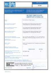
”This report is not valid as a CB Test Report unless appended to a CB Test Certificate issued by a NCB, in<br />
accordance <strong>with</strong> <strong>IEC</strong>EE 02”.<br />
This report shall not be reproduced <strong>with</strong>out the written approval of the applicant.<br />
The test results presented in this report relate only to the item(s) tested.<br />
”(See remark #)" refers to a remark appended to the report.<br />
"(See Annex #)" refers to an annex appended to the report.<br />
Throughout this report a comma is used as the decimal separator.<br />
History sheet<br />
Date Name Change Revision No<br />
2002-05-10 T223-0138/02 Initial test report issued.<br />
2002-05-24 T223-0152/02 Manufacturer changed the name of the product and<br />
alternatively name of the model.<br />
1.0
Page 3 of 102<br />
<strong>IEC</strong> <strong>60950</strong><br />
T223-0152/02<br />
List of Acceptability/ Summary of Testing<br />
Clause Information/Remarks Comments<br />
1.0 Component This component has been judged on the basis of<br />
the required spacing in the Standard of<br />
Information Technology Equipment, Including<br />
Electrical Business Equipment, CAN/CSA 22.2 –<br />
<strong>60950</strong> * UL <strong>60950</strong>, Third <strong>Edition</strong>, which are based<br />
on the <strong>IEC</strong> <strong>60950</strong>, Third <strong>Edition</strong> 1999.<br />
1.2.5.1 Connection to the Supply<br />
The terminals and connectors are suitable for field<br />
wiring <strong>with</strong> the restriction of using ferrules.<br />
The unit is tested for connection to mains <strong>with</strong> a<br />
maximum 32 A branch circuit.<br />
2.10 Pollution degree The equipment has been evaluated for use in a<br />
Pollution Degree 2 environment.<br />
2.2 SELV circuits The outputs are SELV, hazardous energy level.<br />
2.6.0 Provisions for earthing and bonding The equipment shall be property bonded to the<br />
main protective earthing.<br />
2.9.1 Properties of insulating materials The transformer T1 employs an R/C (OBJY2)<br />
electrical insulation system Class F1<br />
4.5.0 Thermal requirements The following components should be given special<br />
consideration during end-use Heating test<br />
because of temperatures achieved during<br />
component level testing:<br />
Component:<br />
T1 winding<br />
Maximum temperature Achieved<br />
108,2 °C (60 °C ambient).<br />
4.6.0 Openings in enclosure The power supply will require fire and electrical<br />
enclosure.<br />
5.2 Electric strength The maximum working voltage present is 420 V<br />
peak, 309 V RMS (<strong>with</strong> DC input voltage).The<br />
electric strength tests for the Power Supply should<br />
be based on this value.
Page 4 of 102<br />
<strong>IEC</strong> <strong>60950</strong><br />
T223-0152/02<br />
ADDITIONAL INFORMATION<br />
DESCRIPTION OF EQUIPMENT UNDER TEST<br />
Switch mode power supply <strong>with</strong> ASI bus connection.<br />
NAME AND ADDRESS OF PRODUCTION-SITES (FACTORIES):<br />
See page 1.<br />
INFORMATION ABOUT THE STANDARDS / DOCUMENTS CONSIDERED<br />
<strong>IEC</strong> <strong>60950</strong>, 3 rd <strong>Edition</strong>: 1999<br />
EN <strong>60950</strong>, 3 rd <strong>Edition</strong>: 2000<br />
TESTED ACCORDING TO NATIONAL REQUIREMENTS FOR THE FOLLOWING COUNTRIES:<br />
All CENELEC members as listed in EN <strong>60950</strong>:2000.<br />
All CB members as listed in CB Bulletin 101A, December 2001<br />
LIST OF APPENDIXES / ENCLOSURES TO THE TEST REPORT<br />
Appendix EN <strong>60950</strong>: 2000 Page 64<br />
GROUP DIFFERENCES Page 74<br />
Australian deviations (including New Zealand) Page 77<br />
Canadian deviations. Page 86<br />
Israeli deviations Page 91<br />
Japanese deviations. Page 92<br />
Korean deviations Page 96<br />
Norwege deviations Page 96<br />
Sweden deviations Page 98<br />
US Deviations Page 99
Page 5 of 102<br />
T223-0152/02<br />
<strong>IEC</strong> <strong>60950</strong><br />
Clause Requirement - Test Result - Remark Verdict<br />
1 GENERAL —<br />
1.1 SCOPE —<br />
1.1.1 Equipment covered by this<br />
standard<br />
The product is <strong>with</strong>in the scope of <strong>IEC</strong> <strong>60950</strong>. —<br />
1.1.2 Additional requirements: —<br />
Exposure to extreme temperatures,<br />
excessive dust, moisture or<br />
vibration; to flammable gases; to<br />
corrosive or explosive atmospheres<br />
Electro medical equipment<br />
connected to the patient<br />
Equipment used in vehicles, ships<br />
or aircrafts, in tropical countries, or<br />
at elevations > 2000m<br />
Equipment intended for use where<br />
ingress of water is possible<br />
This equipment is intended to operate in a "normal"<br />
environment (Offices and homes).<br />
This equipment is not an electro medical equipment<br />
intended to be physically connected to a patient.<br />
This equipment is intended to operate in a "normal"<br />
environment (Offices and homes).<br />
This equipment is intended to be used in applications<br />
where ingress of water is not regarded possible. The<br />
equipment is non-protected according to <strong>IEC</strong> 60529.<br />
—<br />
—<br />
—<br />
—<br />
IP-classification (<strong>IEC</strong> 60529) (IP) Minimum IP 20. —<br />
1.2.2 OPERATING CONDITIONS —<br />
1.2.2.1 Normal load as described in Annex<br />
L or as close as possible to the<br />
most severe normal use<br />
See Load description page 2 —<br />
1.2.2.2 Rated operating time as assigned<br />
by the manufacturer<br />
1.2.2.3 - 1.2.2.5 Continuous operation /<br />
Short-time operation/ Intermittent<br />
operation<br />
The manufacturer has not declared a rated operating<br />
time.<br />
The equipment is regarded to be for continuous<br />
operation.<br />
—<br />
—
Page 6 of 102<br />
T223-0152/02<br />
<strong>IEC</strong> <strong>60950</strong><br />
Clause Requirement - Test Result - Remark Verdict<br />
1.5 COMPONENTS P<br />
1.5.1 General Ref. List of Critical Components. P<br />
1.5.2 Evaluation and testing of<br />
components<br />
Dimensions of mains plug for direct<br />
plug-in equipment<br />
Additional torque (Nm)<br />
Pull (N)<br />
Certified components are used in accordance <strong>with</strong> their<br />
ratings, certifications and they comply <strong>with</strong> applicable<br />
parts of this standard.<br />
Components not certified are used in accordance <strong>with</strong><br />
their ratings and they comply <strong>with</strong> applicable parts of<br />
<strong>IEC</strong> <strong>60950</strong> and the relevant component standard.<br />
Components, for which no relevant <strong>IEC</strong>-standard exists,<br />
have been tested under the conditions occurring in the<br />
equipment, using applicable parts of <strong>IEC</strong> <strong>60950</strong>.<br />
Not a direct plug-in equipment.<br />
P<br />
N<br />
N<br />
1.5.3 Thermal controls No thermal controls. N<br />
1.5.4 Transformers Transformers used are suitable for their intended<br />
applications and comply <strong>with</strong> relevant parts of this<br />
standard and particularly Annex C, see Annex C –<br />
Transformers and list of critical components.<br />
P<br />
1.5.5 Interconnecting cables No interconnecting cables. N<br />
1.5.6 Capacitors in primary circuits<br />
1.5.7.1 - 1.5.7.3 Double or reinforced<br />
insulation bridged by components<br />
1.5.8 Components in equipment for IT<br />
power systems<br />
X1 or X2 and Y1 or Y2 capacitors according to <strong>IEC</strong><br />
60384-14:1993.<br />
No such components bridging double or reinforced<br />
insulation.<br />
Certified capacitors connected between line and earth,<br />
ref. List of Critical Components.<br />
P<br />
N<br />
P<br />
1.5 LIST OF CRITICAL COMPONENTS P<br />
The list of safety critical components is located in the test section. The components were reviewed for the<br />
appropriate rating, the appropriate approvals and for the appropriate use.<br />
1.6 POWER INTERFACE P<br />
1.6.1 A.C. power distribution systems TN and IT<br />
—<br />
1.6.2 Input current Rated 6,0/ 2,8 A —<br />
Test voltage (at each rated voltage<br />
or at each end of a rated voltage<br />
range)<br />
100 – 120 Vac / 220 – 240 Vac<br />
230-375 Vdc<br />
—<br />
Measured current Refer to enclosed test results —<br />
Deviation<br />
The input current measured is below 1,1 times of the<br />
rated current.<br />
P
Page 7 of 102<br />
T223-0152/02<br />
<strong>IEC</strong> <strong>60950</strong><br />
Clause Requirement - Test Result - Remark Verdict<br />
1.6.3 Voltage limit of hand-held<br />
equipment (max. 250V)<br />
1.6.4 Neutral conductor<br />
The equipment is not hand-held.<br />
Neutral is insulated from earth <strong>with</strong> basic insulation<br />
throughout the equipment.<br />
N<br />
P<br />
1.7 MARKINGS AND INSTRUCTIONS P<br />
1.7.1 Power rating The required marking is located on the outside surface<br />
of the equipment.<br />
P<br />
Rated voltage(s) or voltage<br />
range(s)<br />
Symbol for nature of supply for d.c.<br />
Rated frequency or frequency<br />
range<br />
100-120 / 220-240 Vac P<br />
The equipment is for a.c. supply.<br />
The dc supply is described in the manual, but not<br />
marked on the outside to avoid confusion.<br />
50 – 60 Hz<br />
N<br />
P<br />
Rated current 6,0/ 2,8 A P<br />
Manufacturers name, trade mark or<br />
identification mark<br />
PULS or brand name : IFM<br />
P<br />
Type / model<br />
Symbol of Class II The equipment is Class I.<br />
Other symbols<br />
The additional marking does not give rise to<br />
misunderstandings.<br />
P<br />
N<br />
P<br />
Certification marks Refer to copy of markings. —<br />
1.7.2 Safety instructions Must be checked in the end product. N<br />
Operating instructions Must be checked in the end product. N<br />
1.7.3 Short duty cycles The equipment is intended for continuous operation. N<br />
1.7.4 Supply voltage adjustment Voltage selector 115 V or 230 V is not operator<br />
accessible. The means of adjustment is a simple control<br />
on the front side. An instruction is applied to the<br />
equipment.<br />
P<br />
1.7.5 Power outlets on the equipment No standard power outlet. N<br />
1.7.6 Fuse identification Fuse locations and markings: described in the manual. P<br />
1.7.7 Wiring terminals Refer below: —<br />
1.7.7.1 Protective earthing and bonding<br />
terminals<br />
1.7.7.2 Terminals for a.c. mains supply<br />
conductors<br />
Terminal for connection of protective earthing conductor<br />
is marked <strong>with</strong> standard earth symbol (<strong>IEC</strong> 60417-2 No.<br />
5017) near the terminal.<br />
The terminal for the neutral conductor is marked <strong>with</strong> the<br />
capital letter “N”.<br />
1.7.8 Controls and indicators Refer below: —<br />
P<br />
P<br />
1.7.8.1 Identification, location and marking The function of controls affecting safety is obvious<br />
<strong>with</strong>out knowledge of language etc.<br />
P
Page 8 of 102<br />
T223-0152/02<br />
<strong>IEC</strong> <strong>60950</strong><br />
Clause Requirement - Test Result - Remark Verdict<br />
1.7.8.2 Colors For functional indication a LED lights when the<br />
equipment is operating.<br />
P<br />
1.7.8.3 Symbols There are no mains switches in the equipment. N<br />
1.7.8.4 Marking using figures No controls in the sense of this clause. N<br />
1.7.9 Isolation of multiple power sources Only one connection supplying hazardous voltages and<br />
energy levels to the equipment.<br />
1.7.10 IT power system The following information should be given in the<br />
installation instruction: "This product is also designed for<br />
IT power distribution system ".<br />
N<br />
—<br />
1.7.11 Thermostats and other regulating<br />
devices<br />
No thermostats or other regulating devices.<br />
N<br />
1.7.12 Language Instructions and markings shall be in a language<br />
acceptable for the country where the equipment is to be<br />
used.<br />
—<br />
1.7.13 Durability The marking <strong>with</strong>stands required tests. P<br />
1.7.14 Removable parts No removable parts. N<br />
1.7.15 Replaceable batteries No lithium battery in the equipment. N<br />
Language<br />
1.7.16 Operator access <strong>with</strong> a tool<br />
1.7.17 Equipment for restricted access<br />
locations<br />
The unit is for built in use not operator accessible.<br />
Equipment not intended for installation in RAL.<br />
N<br />
N<br />
N
Page 9 of 102<br />
T223-0152/02<br />
<strong>IEC</strong> <strong>60950</strong><br />
Clause Requirement - Test Result - Remark Verdict<br />
Copy of the markings (include all relevant equipment markings):<br />
P<br />
Front Label SLA8.100<br />
Rating Label SLA8.100<br />
Front Label AC1218<br />
Rating Label AC1218
Page 10 of 102<br />
T223-0152/02<br />
<strong>IEC</strong> <strong>60950</strong><br />
Clause Requirement - Test Result - Remark Verdict<br />
2 PROTECTION FROM HAZARDS P<br />
2.1 PROTECTION FROM ELECTRIC<br />
SHOCK AND ENERGY HAZARDS<br />
P<br />
2.1.1 Protection in operator access areas Refer below: —<br />
2.1.1.1 Access to energized parts Built in Power Supply N<br />
2.1.1.2 Battery compartments No TNV circuits in the equipment. N<br />
2.1.1.3 Access to ELV wiring No internal wiring at ELV. N<br />
2.1.1.4 Access to hazardous voltage circuit<br />
wiring<br />
2.1.1.5 Energy hazards The output from the power supply represents an energy<br />
hazard. Must be considered for the end product. See<br />
test results enclosed.<br />
N<br />
N<br />
2.1.1.6 Manual controls No shafts of knobs etc. at ELV or hazardous voltage. N<br />
2.1.1.7 Discharge of capacitors in the<br />
primary circuit<br />
The capacitance of the input circuit is > 0,1µF. The<br />
measurements were performed in worst-case condition.<br />
P<br />
Time-constant (s) The time constant is < 1 sec. P<br />
2.1.2 Protection in service access areas Checked by inspection, unintentional contact is unlikely<br />
during service operations.<br />
P<br />
2.1.3 Protection in restricted access<br />
locations<br />
Equipment not intended for installation in RAL.<br />
N<br />
2.2 SELV CIRCUITS P<br />
2.2.1 General requirements SELV limits (at accessible parts) are not exceeded<br />
under normal condition and after a single fault.<br />
2.2.2 Voltages under normal conditions Within SELV limits. (See enclosed test results)<br />
2.2.3 Voltage under fault conditions Single fault conditions:
Page 11 of 102<br />
T223-0152/02<br />
<strong>IEC</strong> <strong>60950</strong><br />
Clause Requirement - Test Result - Remark Verdict<br />
2.5 LIMITED POWER SOURCES No limited power source. N<br />
2.6 PROVISIONS FOR EARTHING<br />
AND BONDING<br />
The built in equipment shall be properly bonded to the<br />
main protective earthing.<br />
2.6.1 Protective earthing The unit is for built in. The enclosure is not intended for<br />
operator contact: the enclosure is properly bonded.<br />
Warning label for service<br />
personnel. Warning label:<br />
2.6.2 Functional earthing<br />
No functional earthing is provided.<br />
P<br />
P<br />
N<br />
N<br />
2.6.3 Protective earthing and protective<br />
bonding conductors<br />
Refer below: —<br />
2.6.3.1 Size of protective earthing<br />
conductors<br />
2.6.3.2 Size of protective bonding<br />
conductors<br />
2.6.3.3 Resistance of earthing conductors<br />
and their terminations<br />
Power supply cord not provided <strong>with</strong> the equipment.<br />
The bonding is done via the PCB board <strong>with</strong> a screw M4<br />
from PCB to enclosure.<br />
From the earth terminal to the chassis : (see below)<br />
N<br />
P<br />
P<br />
Test current See enclosed test results. P<br />
2.6.3.4 Color of insulation<br />
The built in Power Supply does not provide wiring (for<br />
earthing.<br />
N<br />
2.6.4 Terminals Refer below: —<br />
2.6.4.1 Protective earthing and bonding<br />
terminals<br />
2.6.4.2 Separation of the protective<br />
earthing conductors from protective<br />
bonding conductors<br />
See list of safety critical components.<br />
Approved terminal used.<br />
P<br />
P<br />
2.6.5 Integrity of protective earthing Refer below: —<br />
2.6.5.1 Interconnection of equipment No interconnection of equipment. N<br />
2.6.5.2 Components in protective earthing<br />
conductors and protective bonding<br />
conductors<br />
2.6.5.3 Disconnection of protective earth<br />
2.6.5.4 Parts that can be removed by an<br />
operator<br />
There are no switches or over current protective devices<br />
in the protective earthing / bonding conductors.<br />
The Power Supply is for built in use.<br />
No operator removable parts.<br />
N<br />
N<br />
N<br />
2.6.5.5 Parts removed during servicing Protective earthed parts cannot be removed in a way,<br />
which impair safety.<br />
P<br />
2.6.5.6 Corrosion resistance No risk of corrosion. N<br />
2.6.5.7 Screws for protective bonding Adequate connection of protective bonding. P
Page 12 of 102<br />
T223-0152/02<br />
<strong>IEC</strong> <strong>60950</strong><br />
Clause Requirement - Test Result - Remark Verdict<br />
2.6.5.8 Reliance on telecommunication<br />
network<br />
Protective earthing does not rely on a<br />
telecommunication network.<br />
N<br />
2.7 OVERCURRENT AND EARTH<br />
FAULT PROTECTION IN<br />
PRIMARY CIRCUITS<br />
P<br />
2.7.1 Basic requirements Protective devices are integrated in the equipment, see<br />
also Sub-clause 5.3.<br />
P<br />
Instruction when protection relies<br />
on building installation<br />
Protective devices are integrated in the equipment.<br />
P<br />
2.7.2 Faults not covered in 5.3 Considered. P<br />
2.7.3 Short-circuit backup protection Adequate protective device. P<br />
2.7.4 Number and location of protective<br />
devices<br />
Single fuse in identified Line.<br />
P<br />
2.7.5 Protection by several devices Only one protective device. See Sub-clause 2.7.4. N<br />
2.7.6 Warning to service personnel Single fuse in identified Line. In case of one fault the<br />
equipment might still be under power in case of an IT<br />
system. The unit is for built in use. A warning mark for<br />
the service engineer was not considered as required and<br />
might be necessary <strong>with</strong>in the end product.<br />
N<br />
2.8 SAFETY INTERLOCKS 2.8.1 – 2.8.8; No safety interlocks. N<br />
2.9 ELECTRICAL INSULATION P<br />
2.9.1 Properties of insulating materials Neither natural rubber, materials containing asbestos<br />
nor hygroscopic materials are used as insulation. No<br />
driving belts or couplings used.<br />
P<br />
2.9.2 Humidity conditioning Humidity treatment performed for 48h at 91-95%. P<br />
2.9.3 Requirements for insulation The insulation complies <strong>with</strong> sub-clauses 4.5.1, 5.2 and<br />
2.10.<br />
2.9.4 Insulation parameters Application of insulation and working voltage are<br />
considered.<br />
2.9.5 Categories of insulation Insulation is considered to be functional, basic,<br />
supplementary, reinforced or double insulation.<br />
P<br />
P<br />
P<br />
2.10 CLEARANCES, CREEPAGE<br />
DISTANCES AND DISTANCES<br />
THROUGH INSULATION<br />
See enclosed test results<br />
P<br />
Nominal voltage > 150V ≤ 300V P<br />
Pollution degree II —
Page 13 of 102<br />
T223-0152/02<br />
<strong>IEC</strong> <strong>60950</strong><br />
Clause Requirement - Test Result - Remark Verdict<br />
CTI rating PCB: III —<br />
Other parts: III —<br />
2.10.1 General Considered, see the following clauses: —<br />
2.10.2 Determination of working voltage Considered. N<br />
2.10.3 Clearances See table 2.10.3 N<br />
2.10.3.1 General Refer below: —<br />
10mm air gap between hazardous<br />
voltage and accessible conductive<br />
parts of enclosure<br />
2mm air gap between hazardous<br />
voltage and earthed accessible<br />
conductive parts of enclosure<br />
Not applicable.<br />
Not applicable.<br />
N<br />
N<br />
2.10.3.2 Clearances in primary circuits See table 2.10.3 enclosed P<br />
2.10.3.3 Clearances in secondary circuits Only functional insulation in secondary circuits, ref. 5.2. P<br />
2.10.3.4 Measurements of transient levels Measurement not relevant. N<br />
2.10.4 Creepage distances See table 2.10.4 enclosed P<br />
2.10.5 Solid insulation Refer below: —<br />
2.10.5.1 Minimum distance through<br />
insulation<br />
See table enclosed<br />
P<br />
2.10.5.2 Thin sheet material Ref. Annex C and table 2.10.5 P<br />
2.10.5.3 Printed boards Thickness of the main PCB board is > 0,4 mm. P<br />
2.10.5.4 Wound components P<br />
Two wires in contact inside<br />
component<br />
N<br />
2.10.6 Coated printed boards No special coating in order to reduce distances. N<br />
2.10.6.1 General Refer below: —<br />
2.10.6.2 Sample preparation and preliminary<br />
inspection<br />
N<br />
2.10.6.3 Thermal cycling N<br />
2.10.6.4 Thermal ageing N<br />
2.10.6.5 Electric strength test N<br />
2.10.6.6 Abrasion resistance test N
Page 14 of 102<br />
T223-0152/02<br />
<strong>IEC</strong> <strong>60950</strong><br />
Clause Requirement - Test Result - Remark Verdict<br />
2.10.7 Enclosed and sealed parts For optical insulators, see Appendix – Optical Electronic<br />
Devices.<br />
P<br />
2.10.8 Spacing filled by insulating<br />
compound<br />
For optical insulators, see Appendix – Optical Electronic<br />
Devices.<br />
P<br />
2.10.9 Component external terminations See Sub-clauses 2.10.1 up to and including 2.10.4. P<br />
2.10.10 Insulation <strong>with</strong> varying dimensions No such transformer used. N<br />
3 WIRING, CONNECTIONS AND<br />
SUPPLY<br />
P<br />
3.1 GENERAL P<br />
3.1.1 Current rating and over current<br />
protection<br />
3.1.2 Protection against mechanical<br />
damage<br />
No internal wiring.<br />
No internal wiring.<br />
N<br />
N<br />
3.1.3 Securing of internal wiring No internal wiring. N<br />
3.1.4 Insulation of conductors No internal wiring. N<br />
3.1.5 Beads and ceramic insulators No beads or similar ceramic insulators on conductors. N<br />
3.1.6 Screws for electrical contact<br />
pressure<br />
3.1.7 Non-metallic materials in electrical<br />
connections<br />
3.1.8 Self-tapping and spaced thread<br />
screws<br />
Electrical screw connection is only connecting protective<br />
earth to chassis. Metal screw engages more than 2<br />
threads. Screws made of insulating material are not<br />
used where electrical connections, including protective<br />
earthing, are involved.<br />
No contact pressure through insulating material.<br />
Thread-cutting or space thread screws are not used for<br />
electrical connections.<br />
P<br />
P<br />
N<br />
3.1.9 Termination of conductors No internal conductors. N<br />
10N force test<br />
3.1.10 Sleeving on wiring No internal wiring (transformer outlets were not<br />
considered as internal wiring).<br />
N<br />
N
Page 15 of 102<br />
T223-0152/02<br />
<strong>IEC</strong> <strong>60950</strong><br />
Clause Requirement - Test Result - Remark Verdict<br />
3.2 CONNECTION TO A.C. MAINS<br />
SUPPLIES<br />
Built in product <strong>with</strong> appropriate and approved terminals.<br />
3.2.1 Means of connection Built in Power Supply <strong>with</strong> approved connector (see list<br />
of safety critical components).<br />
Only one supply connection.<br />
3.2.2 Multiple supply connections<br />
3.2.3 Permanently connected equipment<br />
3.2.4 Appliance inlets<br />
The equipment is not intended for permanent connection<br />
to the mains.<br />
No appliance inlet is used.<br />
3.2.5 Power supply cords<br />
Power supply cord is not provided (built in Power<br />
Supply).<br />
3.2.6 Cord anchorages and strain relief Equipment is not provided <strong>with</strong> an appliance inlet.<br />
P<br />
P<br />
N<br />
N<br />
N<br />
N<br />
N<br />
3.2.5 Mass of equipment, pull N<br />
Longitudinal displacement ≤ 2mm<br />
3.2.7 Protection against mechanical<br />
damage<br />
No sharp points or cutting edges on the equipment<br />
surfaces.<br />
3.2.8 Cord guards The equipment is neither hand-held nor intended to be<br />
moved during operation.<br />
D = (mm) —<br />
Test <strong>with</strong> mass of (g) —<br />
Radius of curvature of cord —<br />
3.2.9 Supply wiring space The supply wiring space is satisfactory. P<br />
N<br />
P<br />
N<br />
3.3 WIRING TERMINALS FOR<br />
CONNECTION OF EXTERNAL<br />
CONDUCTORS<br />
P<br />
3.3.1 Wiring terminals Screw terminals are used. P<br />
3.3.2 Connection of non-detachable<br />
power supply cords<br />
Adequate connection, checked by inspection.<br />
P<br />
3.3.3 Screw terminals Screws do not clamp the external supply wiring. P<br />
3.3.4 Conductor sizes to be connected See list of safety critical components. P<br />
3.3.5 Wiring terminal sizes 05-6 mm 2 P<br />
3.3.6 Wiring terminal design Screw terminal P<br />
3.3.7 Grouping of wiring terminals P<br />
3.3.8 Stranded wire<br />
The terminals are suitable for field wiring <strong>with</strong> the<br />
restriction of using ferrules.<br />
N
Page 16 of 102<br />
T223-0152/02<br />
<strong>IEC</strong> <strong>60950</strong><br />
Clause Requirement - Test Result - Remark Verdict<br />
3.4 DISCONNECTION FROM THE<br />
A.C. MAINS SUPPLY<br />
Built in power supply <strong>with</strong>out disconnect device.<br />
N<br />
3.4.1 General requirement See Sub-clause 3.4.2. —<br />
3.4.2 Disconnect devices The unit is a built in Power Supply and does not provide<br />
a disconnect device.<br />
Contact separation<br />
N<br />
N<br />
3.4.3 Permanently connected equipment Not permanently connected equipment. N<br />
3.4.4 Parts which remain energized N<br />
3.4.5 Switches in flexible cords N<br />
3.4.6 Single-phase equipment N<br />
3.4.7 Three-phase equipment Single phase equipment. N<br />
3.4.8 Switches as disconnect devices No switch as disconnect device. N<br />
3.4.9 Plugs as disconnect devices N<br />
3.4.10 Interconnected equipment N<br />
3.4.11 Multiple power sources One power source only. N<br />
3.5 INTERCONNECTION OF<br />
EQUIPMENT<br />
P<br />
3.5.1 General requirements Considered. P<br />
3.5.2 Types of interconnection circuits SELV circuit P<br />
3.5.3 ELV circuits as interconnection<br />
circuits<br />
No ELV interconnections.<br />
N<br />
4 PHYSICAL REQUIREMENTS P<br />
4.1 STABILITY Refer below: —<br />
Angle of 10°<br />
Test: force (20% of the weight of<br />
the unit, max. 250N)<br />
The unit is not floor standing.<br />
N<br />
N<br />
Test: force (800N) The unit is not floor standing. N<br />
4.2 MECHANICAL STRENGTH P<br />
4.2.1 General Refer below —<br />
4.2.2 Steady force test, 10N No hazard, ref. To test results enclosed. P<br />
4.2.3 Steady force test, 30N No enclosure located in operator access area. N
Page 17 of 102<br />
T223-0152/02<br />
<strong>IEC</strong> <strong>60950</strong><br />
Clause Requirement - Test Result - Remark Verdict<br />
4.2.4 Steady force test, 250N No external enclosure.<br />
N<br />
4.2.5 Impact test —<br />
Fall test<br />
Swing test<br />
4.2.6 Drop test Drop test not applicable.<br />
This is a component level power supply. Outer surfaces<br />
intended to form outer enclosure must be tested in end<br />
product.<br />
This is a component level power supply. Outer surfaces<br />
intended to form outer enclosure must be tested in end<br />
product.<br />
N<br />
N<br />
N<br />
4.2.7 Stress relief Enclosure consists out of metal. N<br />
4.2.8 Cathode ray tubes CRT(s) not used in the equipment. N<br />
4.2.9 High pressure lamps No high-pressure lamps in the equipment. N<br />
4.2.10 Wall or ceiling mounted equipment Not intended to be mounted on a wall or ceiling. N<br />
4.3 DESIGN AND CONSTRUCTION P<br />
4.3.1 Edges and corners All edges and corners are rounded and/or smoothed. P<br />
4.3.2 Handles and manual controls No knobs, grips, handles, lever etc. N<br />
4.3.3 Adjustable controls Setting of the voltage only for the service engineer (built<br />
in power supply)<br />
4.3.4 Securing of parts No loosening of parts impairing Creepage distances or<br />
clearances is likely to occur.<br />
P<br />
P<br />
4.3.5 Connection of plugs and sockets<br />
SELV connectors do not comply <strong>with</strong> <strong>IEC</strong> 60320 or <strong>IEC</strong><br />
60083.<br />
P<br />
4.3.6 Direct plug-in equipment Not intended to plug directly into a wall socket-outlet. N<br />
Torque (Nm)<br />
4.3.7 Heating elements in earthed<br />
equipment<br />
No heating elements provided.<br />
N<br />
N<br />
4.3.8 Batteries No batteries in the equipment. N<br />
4.3.9 Oil and grease Insulation is not exposed to oil, grease etc. N<br />
4.3.10 Dust, powders, liquids and gases The equipment does not generate ionizing radiation or<br />
use a laser, and does not contain flammable liquids or<br />
gases.<br />
N<br />
4.3.11 Containers for liquids or gases No containers for liquids or gases in the equipment. N<br />
4.3.12 Flammable liquids The equipment does not contain flammable liquid. N<br />
Quantity of liquid<br />
N
Page 18 of 102<br />
T223-0152/02<br />
<strong>IEC</strong> <strong>60950</strong><br />
Clause Requirement - Test Result - Remark Verdict<br />
Flash point<br />
N<br />
4.3.13 Radiation No radiation in the sense of this clause is generated. N<br />
4.4 PROTECTION AGAINST<br />
HAZARDOUS MOVING PARTS<br />
No moving parts<br />
N<br />
4.4.1 General N<br />
4.4.2 Protection in operators access<br />
areas<br />
No moving parts.<br />
N<br />
4.4.3 Protection in restricted access<br />
locations<br />
N<br />
4.4.4 Protection in service access areas N<br />
4.5 THERMAL REQUIREMENTS P<br />
4.5.1 Temperature rises No thermostats temp. Limiters or thermal cutouts. P<br />
4.5.2 Resistance to abnormal heat See enclosed test results. P<br />
4.6 OPENINGS IN ENCLOSURES Unit does not provide fire and electrical enclosure. N<br />
4.6.1 Top and side openings Refer below: N<br />
Top openings<br />
Openings in top are < 5mm (including diagonal) in any<br />
dimension:<br />
N<br />
Dimension 3,5 mm by 3,5 mm N<br />
Front, side and rear openings No front, side or rear openings. N<br />
Dimension<br />
4.6.2 Bottoms of fire enclosures Bottom of the unit does not fulfill requirements for fire<br />
and electrical enclosure. There are openings 3,5 mm by<br />
3,5 mm in the bottom.<br />
N<br />
N<br />
4.6.3 Doors or covers in fire enclosures No doors or covers in fire enclosure. N<br />
4.6.4 Openings in transportable<br />
equipment<br />
4.6.5 Adhesives for constructional<br />
purposes<br />
Conditioning temperature / time<br />
The unit is not regarded as transportable equipment.<br />
No barrier secured by adhesive inside enclosure.<br />
N<br />
N<br />
N
Page 19 of 102<br />
T223-0152/02<br />
<strong>IEC</strong> <strong>60950</strong><br />
Clause Requirement - Test Result - Remark Verdict<br />
4.7 RESISTANCE TO FIRE P<br />
4.7.1 Reducing the risk of ignition and<br />
spread of flame<br />
Method 1 is used.<br />
P<br />
4.7.2 Conditions for a fire enclosure Fire enclosure must be considered for the end product. N<br />
4.7.2.1 Parts requiring a fire enclosure The fire enclosure is required to cover all parts. N<br />
4.7.2.2 Parts not requiring a fire enclosure The fire enclosure is required to cover all parts. N<br />
4.7.3 Materials Components and materials have adequate flammability<br />
classification. Refer to “List of Critical Components”.<br />
P<br />
4.7.3.1 General Considered. P<br />
4.7.3.2 Materials for fire enclosure N<br />
4.7.3.3 Materials for components and other<br />
parts outside fire enclosures<br />
4.7.3.4 Materials for components and other<br />
parts inside fire enclosures<br />
Equipment for building in must be considered in the end<br />
product.<br />
Other materials inside fire enclosure are minimum V-2<br />
material.<br />
N<br />
P<br />
4.7.3.5 Materials for air filter assemblies No air filters in the equipment. N<br />
4.7.3.6 Materials used in high-voltage<br />
components<br />
No parts exceeding 4kV.<br />
N<br />
5 ELECTRICAL REQUIREMENTS<br />
AND SIMULATED ABNORMAL<br />
CONDITIONS<br />
P<br />
5.1 Touch current and protective<br />
conductor current<br />
Refer below —<br />
5.1.1 General Test conducted in accordance <strong>with</strong> 5.1.2 to 5.1.7. P<br />
5.1.2 Equipment under test (EUT) No interconnected equipment or multiple power sources. N<br />
5.1.3 Test circuit Tested for connection to IT power distribution system<br />
(also relevant for TN or TT power distribution system).<br />
P<br />
5.1.4 Application of measuring instrument Measuring instrument D1 is used. P<br />
5.1.5 Test procedure According to the standard. P<br />
5.1.6 Test measurements See enclosed test results. P<br />
5.1.7 Equipment <strong>with</strong> touch current<br />
exceeding 3.5mA<br />
5.1.8 Touch currents to and from<br />
telecommunication networks<br />
5.1.8.1 Limitation of the touch current to a<br />
telecommunication network<br />
The touch current does not exceed 3,5mA.<br />
Not connected to a telecommunication network.<br />
Not connected to a telecommunication network.<br />
N<br />
N<br />
N
Page 20 of 102<br />
T223-0152/02<br />
<strong>IEC</strong> <strong>60950</strong><br />
Clause Requirement - Test Result - Remark Verdict<br />
Test voltage<br />
Measured current<br />
Max. allowed current<br />
5.1.8.2 Summation of touch currents from<br />
telecommunication networks<br />
Not connected to a telecommunication network.<br />
N<br />
N<br />
N<br />
N<br />
5.2 ELECTRIC STRENGTH For details see enclosed test results. P<br />
5.2.1 - 5.2.2 General. Test procedure Considered. P<br />
5.3 ABNORMAL OPERATING AND<br />
FAULT CONDITIONS<br />
5.3.1 Protection against overload and<br />
abnormal operation<br />
See enclosed test results.<br />
P<br />
P<br />
5.3.2 Motors There are no motors in the equipment. N<br />
5.3.3 Transformers See Annex C. P<br />
5.3.4 Functional insulation Complies <strong>with</strong> a) and c). P<br />
5.3.5 Electromechanical components No electromechanical components in secondary circuits. N<br />
5.3.6 Simulation of faults See the enclosed fault condition tests. P<br />
5.3.7 Unattended equipment No thermostats, temperature limiters or thermal cutouts. N<br />
5.3.8 Compliance criteria for abnormal<br />
operating and fault conditions<br />
Refer below: —<br />
5.3.8.1 During the tests No fire or molten metal occurred and no deformation of<br />
enclosure during the tests.<br />
5.3.8.2 After the tests No reduction of clearance and Creepage distances.<br />
Electric strength test is made on basic, supplementary<br />
and reinforced insulation. See enclosed test results.<br />
P<br />
P<br />
6 CONNECTION TO<br />
TELECOMMUNICATION<br />
NETWORKS<br />
No TNV circuits in the equipment.<br />
N<br />
ANNEX A<br />
TESTS FOR RESISTANCE TO<br />
HEAT AND FIRE<br />
All materials have suitable flame class, no testing<br />
required.<br />
N<br />
ANNEX B<br />
MOTOR TESTS UNDER<br />
ABNORMAL CONDITIONS<br />
No motors in the equipment.<br />
N
Page 21 of 102<br />
T223-0152/02<br />
<strong>IEC</strong> <strong>60950</strong><br />
Clause Requirement - Test Result - Remark Verdict<br />
ANNEX C TRANSFORMERS P<br />
Position Primary to Secondary —<br />
Manufacturer's name PULS —<br />
Manufacturer's designation T6 —<br />
Rated values —<br />
C.1 Short and Overload test See Simulation of Faults enclosed P<br />
Ferro-resonant transformer<br />
N<br />
Type of thermal cut-out No N<br />
C.2 Insulation Transformer TR6 provides reinforced insulation between<br />
primary and secondary windings. The insulation fulfil the<br />
requirements in 2.10 and relevant tests of 5.2.2<br />
P<br />
Precautions taken<br />
Retaining of end turns of all<br />
windings<br />
Earthing test at 25 A<br />
Insulation is provided between windings consisting of<br />
sheet insulation extending beyond the end turns of each<br />
layer.<br />
Secured to the soldering pins <strong>with</strong> wrapping.<br />
P<br />
P<br />
N<br />
Comments<br />
The tested transformer is in compliance <strong>with</strong> the attached specification.
This is an extract of the CB-Scheme report <strong>with</strong> the most important information.<br />
If a complete copy of the report is required, please contact your PULS sales representative.