Induction Motor Load Dynamics: Impact on Voltage Recovery ...
Induction Motor Load Dynamics: Impact on Voltage Recovery ...
Induction Motor Load Dynamics: Impact on Voltage Recovery ...

Create successful ePaper yourself
Turn your PDF publications into a flip-book with our unique Google optimized e-Paper software.
1<br />
<str<strong>on</strong>g>Inducti<strong>on</strong></str<strong>on</strong>g> <str<strong>on</strong>g>Motor</str<strong>on</strong>g> <str<strong>on</strong>g>Load</str<strong>on</strong>g> <str<strong>on</strong>g>Dynamics</str<strong>on</strong>g>: <str<strong>on</strong>g>Impact</str<strong>on</strong>g> <strong>on</strong><br />
<strong>Voltage</strong> <strong>Recovery</strong> Phenomena<br />
George K. Stefopoulos, Student Member, IEEE, A. P. Meliopoulos, Fellow, IEEE<br />
School of Electrical and Computer Engineering, Georgia Institute of Technology, Atlanta, GA 30332<br />
<br />
Abstract—This paper addresses the impact of load dynamics,<br />
and in particular inducti<strong>on</strong> motor loads, <strong>on</strong> voltage recovery<br />
after disturbances. The paper proposes a methodology that is<br />
based <strong>on</strong> load flow techniques with advanced modeling<br />
capabilities, augmented by a simplified inducti<strong>on</strong> motor dynamic<br />
model. The objective is to realistically capture the dynamic<br />
characteristics of voltage recovery phenomena, avoiding,<br />
however, the full scale transient simulati<strong>on</strong>. The approach uses<br />
the quadratized power flow model with explicit inducti<strong>on</strong> motor<br />
representati<strong>on</strong>. The paper describes the modeling approach and<br />
the overall methodology for evaluating the load dynamics <strong>on</strong><br />
voltage recovery. Preliminary results of the applicati<strong>on</strong> of the<br />
method <strong>on</strong> a simple power system with load dynamics are also<br />
included in the paper.<br />
Index Terms— Dynamic load modeling, <str<strong>on</strong>g>Inducti<strong>on</strong></str<strong>on</strong>g> motor<br />
model, <str<strong>on</strong>g>Load</str<strong>on</strong>g> flow analysis, <strong>Voltage</strong> recovery<br />
T<br />
I. INTRODUCTION<br />
HE paper addresses the issue of voltage recovery<br />
following a disturbance in the presence of load dynamics<br />
arising from several classes of electric loads, such as inducti<strong>on</strong><br />
motors. It is well known that the voltage recovery after a<br />
disturbance in a power system is delayed by load dynamics<br />
(such as the dynamics of inducti<strong>on</strong> motors, etc.), especially<br />
when not enough fast reacting reactive resources (dynamic<br />
VAR sources) exist [1-9]. The phenomen<strong>on</strong> is well known to<br />
utilities and it is typically studied either using static load flow<br />
techniques or with full scale dynamic simulati<strong>on</strong>s. Studies are<br />
performed usually off-line, but <strong>on</strong>-line analysis is also<br />
desirable and possible.<br />
Most off-line studies are based <strong>on</strong> traditi<strong>on</strong>al power flow<br />
analysis that does not take into account the dynamics of the<br />
load, while dynamic off-line studies that take into<br />
c<strong>on</strong>siderati<strong>on</strong> the dynamics of the loads are relatively few and<br />
depend <strong>on</strong> assumed data for the dynamics of the electric load.<br />
Real time tools are almost exclusively based <strong>on</strong> traditi<strong>on</strong>al<br />
power flow models and they are not capable of capturing the<br />
dynamic nature of voltage recovery phenomena. This practice<br />
leads to a disc<strong>on</strong>nect between system analysis and reality<br />
because the load behavior, the majority of which is electric<br />
motors, is not modeled properly.<br />
The issue of load modeling and the effects of dynamic<br />
G. K. Stefopoulos and A. P. Meliopoulos are with the School of Electrical<br />
and Computer Engineering, Georgia Institute of Technology, Atlanta, GA<br />
30332 USA (e-mail: gstefop@ieee.org, sakis.meliopoulos@ece.gatech.edu).<br />
loads <strong>on</strong> voltage phenomena have been studied to a significant<br />
extent in literature [1-17]. In [1] the issues of voltage dips in<br />
3-phase systems after symmetric or asymmetric faults and the<br />
accurate modeling of voltage recovery are addressed. In [2,3]<br />
the voltage recovery phenomena and the effect of inducti<strong>on</strong><br />
motor loads are studied from a practical point of view, based<br />
<strong>on</strong> actual events from utility experience. References [4,5]<br />
study the voltage recovery of wind turbines after shortcircuits.<br />
The issue of mitigating the delayed voltage recovery<br />
using fast VAR resources is addressed in [6-8]. The impact of<br />
inducti<strong>on</strong> motor loads <strong>on</strong> voltage phenomena has also been<br />
studied <strong>on</strong> a more general research basis. Reference [9]<br />
addresses the topic of voltage oscillatory instability caused by<br />
inducti<strong>on</strong> motors, in particular in isolated power systems,<br />
while [10] refers to the impact of inducti<strong>on</strong> motor loads in the<br />
system loadability margins and in the damping of inter-area<br />
oscillati<strong>on</strong>s. Finally, references [11-18] are indicative of<br />
current research approaches and issues in inducti<strong>on</strong> motor<br />
load modeling in power systems.<br />
This paper introduces a new approach to the study of<br />
voltage recovery phenomena that can take into c<strong>on</strong>siderati<strong>on</strong><br />
the dynamic characteristics of the load, while avoiding the<br />
task of performing time-demanding, full-scale dynamic<br />
simulati<strong>on</strong>s. The approach uses load flow techniques with<br />
advanced modeling capabilities that allow a more realistic<br />
representati<strong>on</strong> of load dynamics. While the methodology is<br />
capable of handling various classes of electric loads, we focus<br />
our attenti<strong>on</strong> to inducti<strong>on</strong> motor loads which represents the<br />
majority of electric loads.<br />
The inducti<strong>on</strong> motor n<strong>on</strong>linearities depend <strong>on</strong> the slip and<br />
cause singularities as the slip approaches zero. To avoid<br />
numerical problems, the proposed soluti<strong>on</strong> method is based <strong>on</strong><br />
quadratizati<strong>on</strong> of the inducti<strong>on</strong> motor model. This model is<br />
interfaced with the quadratized power flow model to provide a<br />
robust soluti<strong>on</strong> method for a system with inducti<strong>on</strong> motors. In<br />
additi<strong>on</strong>, this model is a more realistic representati<strong>on</strong> of a<br />
power system without increasing the complexity of the power<br />
flow equati<strong>on</strong>s.<br />
The paper is structured as follows: Secti<strong>on</strong> II elaborates <strong>on</strong><br />
the voltage recovery problem and the issues associated with it.<br />
Secti<strong>on</strong> III presents a brief overview of the main features of<br />
the quadratized power flow model, al<strong>on</strong>g with an inducti<strong>on</strong><br />
motor model for power flow studies. Secti<strong>on</strong> IV introduces the<br />
simplified motor dynamic model that is used in this approach<br />
and illustrates the proposed methodology for the study of<br />
voltage recovery using load flow with dynamic load
2<br />
representati<strong>on</strong>. Secti<strong>on</strong> V presents some preliminary results<br />
with an example test system that comprises inducti<strong>on</strong> motor<br />
loads. Finally, secti<strong>on</strong> VI c<strong>on</strong>cludes the paper.<br />
II. PROBLEM STATEMENT<br />
The problem of transient voltage sags during .disturbances<br />
and recovery after the disturbance has been removed is quite<br />
well known. The importance of the problem has been well<br />
identified; its significance is increasing especially in modern<br />
restructured power systems that may frequently operate close<br />
to their limits under heavy loading c<strong>on</strong>diti<strong>on</strong>s. Furthermore,<br />
the increased number of voltage-sensitive loads and the<br />
requirements for improved power system reliability and power<br />
quality are imposing more strict criteria for the voltage<br />
recovery after severe disturbances. It is well known that slow<br />
voltage recovery phenomena have sec<strong>on</strong>dary effects such as<br />
operati<strong>on</strong> of protective relays, electric load disrupti<strong>on</strong>, motor<br />
stalling, etc. Many sensitive loads may have stricter settings of<br />
protective equipment and therefore will trip faster in the<br />
presence of slow voltage recovery resulting in loss of load<br />
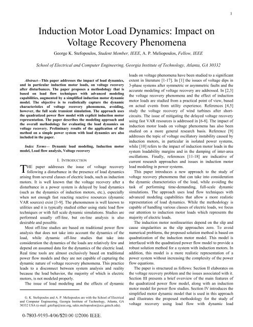
with severe ec<strong>on</strong>omic c<strong>on</strong>sequences. A typical situati<strong>on</strong> of<br />
voltage recovery following a disturbance is illustrated in Fig.<br />
1. Note there is a fault during which the voltage collapses to a<br />
certain value. When the fault clears, the voltage recovers<br />
quickly to another level and then slowly will build up to the<br />
normal voltage. The last period of slow recovery is mostly<br />
affected by the load dynamics and especially inducti<strong>on</strong> motor<br />
behavior.<br />
The objective of the paper is to present a method that can<br />
be used to study voltage recovery events after a disturbance.<br />
More specifically the problem is stated as follows: Assume a<br />
power system with dynamic loads, like, for example,<br />
inducti<strong>on</strong> motors. A fault occurs at some place in the system<br />
and it is cleared by the protecti<strong>on</strong> devices after some period of<br />
time. The objective it to study the voltage recovery after the<br />
disturbance has been cleared at the buses where dynamic or<br />
other sensitive loads are c<strong>on</strong>nected and also determine how<br />
these loads affect the recovery process.<br />
This paper proposes a hybrid approach to the study of<br />
voltage recovery that is based <strong>on</strong> static load flow techniques<br />
taking also into account the essential dynamic features of the<br />
load. This approach provides a more realistic tool compared to<br />
traditi<strong>on</strong>al load flow, avoiding however the full scale transient<br />
simulati<strong>on</strong> which requires detailed system and load dynamic<br />
models.<br />
III. SINGLE-PHASE QUADRATIZED POWER FLOW (SPQPF)<br />
WITH INDUCTION MOTOR REPRESENTATION<br />
A. Overview of Single Phase Quadratized Power Flow<br />
The proposed system modeling is based <strong>on</strong> the single phase<br />
quadratized power flow. The idea of this power flow model is<br />
to have a set of power flow equati<strong>on</strong>s of degree no greater<br />
than two, i.e. have a set of linear or quadratic equati<strong>on</strong>s. This<br />
can be achieved without making any sort of approximati<strong>on</strong>s,<br />
so the power system model is an exact model. Since most of<br />
the equati<strong>on</strong>s turn out to be linear and the degree of<br />
n<strong>on</strong>linearity for the n<strong>on</strong>linear equati<strong>on</strong>s is restricted to at most<br />
two, this results in improved c<strong>on</strong>vergence characteristics in<br />
the iterative soluti<strong>on</strong> and therefore improved executi<strong>on</strong> speed<br />
at no expense in the accuracy of the soluti<strong>on</strong>.<br />
<strong>Voltage</strong> (pu)<br />
1.00<br />
0.95<br />
0.90<br />
0.85<br />
0.80<br />
0.75<br />
0.70<br />
0.65<br />
0.60<br />
Fault<br />
Fault Cleared<br />
<str<strong>on</strong>g>Motor</str<strong>on</strong>g>s will trip<br />
if voltage sags<br />
for too l<strong>on</strong>g<br />
-1.00 -0.50 0.00 0.50 1.00 1.50 2.00<br />
Sec<strong>on</strong>ds<br />
Fig. 1. Possible behavior of voltage recovery during and after a disturbance.<br />
The first step in expressing the power flow equati<strong>on</strong>s in<br />
quadratic form is to avoid the trig<strong>on</strong>ometric n<strong>on</strong>linearities.<br />
This can be achieved by utilizing rectangular coordinates<br />
instead of the traditi<strong>on</strong>ally used polar coordinates for<br />
expressing the voltage phasors. Therefore, the system states<br />
are not the voltage magnitudes and angles, but instead the real<br />
and imaginary parts of the voltage phasors. This results in a<br />
set of polynomial equati<strong>on</strong>s. If the degree of n<strong>on</strong>linearity of<br />
these equati<strong>on</strong>s is more than two, then quadratizati<strong>on</strong> of the<br />
equati<strong>on</strong>s can be achieved by introducing additi<strong>on</strong>al state<br />
variables. Note that the quadratizati<strong>on</strong> is performed without<br />
any approximati<strong>on</strong>s, and the resulting quadratic model is an<br />
exact model.<br />
The system modeling is performed <strong>on</strong> the device level, i.e.<br />
a set of quadratic equati<strong>on</strong>s is used to represent the model of<br />
each device. A generalized comp<strong>on</strong>ent model is used,<br />
representing every device, which c<strong>on</strong>sists of the current<br />
equati<strong>on</strong>s of each device, which relate the current through the<br />
device to the states of the device, al<strong>on</strong>g with additi<strong>on</strong>al<br />
internal equati<strong>on</strong>s that model the operati<strong>on</strong> of the device. The<br />
general form of the model, for any comp<strong>on</strong>ent k , is as in (1)<br />
k<br />
i<br />
<br />
Y<br />
0<br />
<br />
k<br />
x<br />
k<br />
x<br />
<br />
x<br />
<br />
<br />
<br />
k T<br />
k T<br />
k k<br />
F x <br />
1<br />
<br />
k k<br />
F x b , (1)<br />
2<br />
<br />
<br />
<br />
k<br />
i is the current through the comp<strong>on</strong>ent,<br />
x k is the<br />
where<br />
vector of the comp<strong>on</strong>ent states and b k the driving vector for<br />
each comp<strong>on</strong>ent. Matrix Y k models the linear part of the<br />
comp<strong>on</strong>ent and matrices F the n<strong>on</strong>linear (quadratic) part.<br />
k<br />
i
3<br />
Applicati<strong>on</strong> of the c<strong>on</strong>nectivity c<strong>on</strong>straints (Kirchoff’s current<br />
law) at each bus yields the quadratized power flow equati<strong>on</strong>s<br />
for the whole system:<br />
X<br />
0<br />
<br />
Y X X<br />
0<br />
<br />
<br />
<br />
T<br />
T<br />
F1<br />
X <br />
<br />
F2<br />
X b G(<br />
X ) , (2)<br />
<br />
<br />
where<br />
X : system state vector,<br />
Y : linear term coefficient matrix (admittance matrix),<br />
F : quadratic term coefficient matrix,<br />
i<br />
b : driving vector.<br />
The soluti<strong>on</strong> to the quadratic equati<strong>on</strong>s is obtained using<br />
the Newt<strong>on</strong>-Raphs<strong>on</strong> iterative method:<br />
1<br />
X X J X ) G(<br />
X )<br />
(3)<br />
n<br />
n1 (<br />
n1<br />
n1<br />
where<br />
n : iterati<strong>on</strong> step,<br />
J ( ) 1<br />
: Jacobian matrix at iterati<strong>on</strong> n 1.<br />
X n<br />
The Iterative procedure terminates when the norm of the QPF<br />
equati<strong>on</strong>s is less than a defined tolerance.<br />
Therefore, the SPQPF equati<strong>on</strong>s G ( X ) 0 comprise a<br />
different mathematical system of n<strong>on</strong>linear algebraic<br />
equati<strong>on</strong>s compared to the traditi<strong>on</strong>al power flow equati<strong>on</strong>s.<br />
The state vector c<strong>on</strong>sists of the real and imaginary part of the<br />
voltage at each bus and of additi<strong>on</strong>al internal state variables<br />
for each device. Some of these internal states are the<br />
additi<strong>on</strong>al variables introduced for the quadratizati<strong>on</strong> of the<br />
equati<strong>on</strong>s. The system G ( X ) 0 c<strong>on</strong>sists of the current<br />
balance equati<strong>on</strong>s at each bus, plus additi<strong>on</strong>al internal<br />
equati<strong>on</strong>s for each <strong>on</strong>e of the n<strong>on</strong>linear devices that exist in<br />
the system. Most of the equati<strong>on</strong>s are linear equati<strong>on</strong>s. All the<br />
n<strong>on</strong>linear equati<strong>on</strong>s are of order at most quadratic.<br />
B. <str<strong>on</strong>g>Inducti<strong>on</strong></str<strong>on</strong>g> <str<strong>on</strong>g>Motor</str<strong>on</strong>g> Model<br />
Typically inducti<strong>on</strong> motors are represented in power<br />
system studies as c<strong>on</strong>stant power loads. Although this is a<br />
valid representati<strong>on</strong> for steady state operati<strong>on</strong>, inducti<strong>on</strong><br />
motors do not always operate under c<strong>on</strong>stant power,<br />
especially when large deviati<strong>on</strong>s of voltage occur. In reality<br />
inducti<strong>on</strong> motors in steady state operate at a point where the<br />
electro-mechanical torque of the motor equals the mechanical<br />
torque of the electric load. As the voltage at the terminals of<br />
the inducti<strong>on</strong> motor changes, the operating point will change,<br />
the motor will accelerate or decelerate and during transients<br />
the operating point will not be at the intersecti<strong>on</strong> of the<br />
electrical torque curve and the mechanical load torque curve.<br />
We present a model here that can accommodate this behavior.<br />
The model is in quadratic form and it is integrated into the<br />
single phase quadratized power flow. In additi<strong>on</strong>, the model<br />
can be used to determine the operati<strong>on</strong> of the system at a<br />
specific instant of time assuming that the speed of the<br />
inducti<strong>on</strong> motor is fixed (for example, after a disturbance).<br />
The significance of this modeling capability is described with<br />
an example.<br />
The importance of including the load dynamics into the<br />
power flow soluti<strong>on</strong> is illustrated in Figures 2 and 3. The<br />
IEEE 24-bus reliability test system (RTS) is used. Fig. 2<br />
shows the voltage profile after a line c<strong>on</strong>tingency, assuming<br />
c<strong>on</strong>stant power load representati<strong>on</strong>. Green indicates voltage<br />
magnitudes within 5% of the nominal voltage; yellow<br />
indicates a voltages deviati<strong>on</strong> of more than 5%, but less than<br />
10% of the nominal voltage; and red indicates a voltage<br />
deviati<strong>on</strong> of more than 10%. Fig. 3 illustrates the same<br />
c<strong>on</strong>diti<strong>on</strong> assuming that half of the electric load at each bus<br />
has been replaced with inducti<strong>on</strong> motor loads. The difference<br />
between the two figures (i.e. Figures 2 and 3) is that the<br />
inducti<strong>on</strong> motors in Fig. 3 operate at different slip (or speed)<br />
as dictated by the soluti<strong>on</strong> – at the soluti<strong>on</strong> the electromagnetic<br />
torque equals the mechanical torque of the load. The<br />
reactive power absorpti<strong>on</strong> of the inducti<strong>on</strong> motors is different<br />
at different slip values and therefore they affect the voltage<br />
profile of the system. This behavior cannot be captured by a<br />
simple, static, c<strong>on</strong>stant power load model.<br />
Fig. 2. <strong>Voltage</strong> profile of the 24-bus RTS after a line c<strong>on</strong>tingency, with<br />
c<strong>on</strong>stant power load representati<strong>on</strong>.<br />
Fig. 3. <strong>Voltage</strong> profile of the 24-bus RTS after line c<strong>on</strong>tingency, with<br />
inducti<strong>on</strong> motors assuming 2% slowdown.<br />
The inducti<strong>on</strong> motor model is easily included in the SPQPF<br />
formulati<strong>on</strong> without increasing the degree of n<strong>on</strong>linearity and<br />
thus further complicating the equati<strong>on</strong>s. A quadratic inducti<strong>on</strong><br />
machine model has been developed [18] based <strong>on</strong> the typical<br />
steady state equivalent circuit of the inducti<strong>on</strong> motor, shown<br />
in Fig. 4. The model input data include typical motor nominal<br />
(nameplate) data, plus electrical parameters, and mechanical
4<br />
load data. The model supports two mechanical loading<br />
modes: (a) Torque equilibrium (steady state), and (b) C<strong>on</strong>stant<br />
Slip.<br />
~<br />
I dk<br />
BUS k<br />
r 1 jx 1<br />
r 2 jx 2<br />
r 2<br />
( 1- s n )<br />
En<br />
~<br />
jx m<br />
Fig. 4. <str<strong>on</strong>g>Inducti<strong>on</strong></str<strong>on</strong>g> motor equivalent circuit.<br />
1<br />
r 1 + jx 1<br />
1<br />
jx m<br />
1<br />
r 2 + jx 2<br />
= g 1 +jb 1<br />
= jb m<br />
= g 2<br />
+jb 2<br />
Circuit analysis of the inducti<strong>on</strong> motor equivalent circuit<br />
yields the equati<strong>on</strong>s:<br />
~<br />
~ ~<br />
I<br />
dk<br />
( g1<br />
jb1<br />
)( Vk<br />
En<br />
)<br />
~ ~ sn<br />
~ ~<br />
(4)<br />
0 jbm<br />
En<br />
En<br />
( g1<br />
jb1<br />
)( Vk<br />
En<br />
)<br />
r jx s<br />
2<br />
2<br />
n<br />
An additi<strong>on</strong>al equati<strong>on</strong> links the electrical state variables to<br />
the mechanical torque produced by the motor. This equati<strong>on</strong><br />
is derived by equating the mechanical power (torque times<br />
mechanical frequency) to the power c<strong>on</strong>sumed by the variable<br />
resistor in the equivalent circuit of Fig. 4.<br />
T<br />
1 s<br />
2 n<br />
em s<br />
( 1 sn<br />
) I r<br />
(5)<br />
2 2<br />
sn<br />
or<br />
~<br />
0 T <br />
(6)<br />
2<br />
En<br />
snr2<br />
r2<br />
jx2sn<br />
where<br />
S<br />
n<br />
: inducti<strong>on</strong> motor slip,<br />
T : mechanical torque produced by motor,<br />
em<br />
: synchr<strong>on</strong>ous mechanical speed.<br />
s<br />
em<br />
s<br />
Two compact models are defined from the above equati<strong>on</strong>s:<br />
(a) C<strong>on</strong>stant Slip Model (Linear):<br />
~<br />
~<br />
~<br />
I<br />
dk<br />
( g1<br />
jb1<br />
) Vk<br />
( g1<br />
jb1<br />
) En<br />
~<br />
0 (<br />
g jb ) V ( g jb jb<br />
1<br />
1<br />
k<br />
1<br />
1<br />
m<br />
sn<br />
~<br />
) En<br />
r jx s<br />
In the c<strong>on</strong>stant slip mode the motor operates at c<strong>on</strong>stant speed.<br />
The value of the slip is known from the operating speed and<br />
therefore the model is linear. The terminal voltage V ~ and the<br />
k<br />
internal rotor voltage E ~ are the states of the model. Note that<br />
n<br />
the equati<strong>on</strong>s are given in compact complex form. In real<br />
2<br />
2<br />
n<br />
s n<br />
(7)<br />
form, separating real and imaginary parts yields a system of<br />
four linear equati<strong>on</strong>s. The state vector is defined as<br />
T<br />
x V<br />
kr<br />
Vki<br />
Eni<br />
Enr<br />
, where the subscripts r and<br />
i denote real and imaginary parts respectively.<br />
(b) Torque Equilibrium Model (N<strong>on</strong>linear):<br />
~<br />
~ ~<br />
I<br />
dk<br />
( g1 jb1<br />
)( Vk<br />
En<br />
)<br />
~ ~ sn<br />
~ ~<br />
0 jbmEn<br />
En<br />
( g1<br />
jb1<br />
)( Vk<br />
En<br />
) (8)<br />
r2<br />
jx2sn<br />
~ 2<br />
En<br />
0 snr2<br />
Tems<br />
r jx s<br />
2<br />
2<br />
n<br />
In the torque equilibrium model the slip is not c<strong>on</strong>stant and<br />
thus it becomes part of the state vector. Note that this model is<br />
n<strong>on</strong>linear and not quadratic since the sec<strong>on</strong>d and third<br />
equati<strong>on</strong>s c<strong>on</strong>tain high order expressi<strong>on</strong>s of state variables. In<br />
order to quadratize the model equati<strong>on</strong>s, we introduce three<br />
additi<strong>on</strong>al state variables, namely Y ~ n<br />
, W ~ ,<br />
n<br />
U<br />
n<br />
defined as<br />
follows:<br />
~ 1<br />
Yn<br />
(9)<br />
r2<br />
jx2sn<br />
~ ~ ~<br />
Wn<br />
YnEn<br />
(10)<br />
~ ~ *<br />
U W W<br />
(11)<br />
n<br />
n<br />
n<br />
The state vector in this mode is defined as:<br />
T ~ ~<br />
~ ~<br />
x V E s jU Y W .<br />
<br />
k<br />
n<br />
n<br />
n<br />
n<br />
The quadratic model equati<strong>on</strong>s are:<br />
~<br />
~<br />
~<br />
I<br />
dk<br />
( g1<br />
jb1<br />
) Vk<br />
( g1<br />
jb1<br />
) En<br />
~<br />
~ ~<br />
0 (<br />
g1<br />
jb1<br />
) Vk<br />
( g1<br />
j(<br />
b1<br />
bm<br />
)) En<br />
Wnsn<br />
0 Tem s<br />
U<br />
nsnr2<br />
(12)<br />
~ ~ *<br />
0 WnWn<br />
U<br />
n<br />
~ ~<br />
0 r2Y<br />
n<br />
jx2snYn<br />
1<br />
~ ~ ~<br />
0 W Y<br />
E<br />
n<br />
n<br />
n<br />
The first equati<strong>on</strong> gives the stator current of the motor; the<br />
sec<strong>on</strong>d equati<strong>on</strong> comes from the equivalent circuit analysis;<br />
the third equati<strong>on</strong> specifies the torque produced by the motor.<br />
The last three equati<strong>on</strong>s introduce the new variables for the<br />
quadratizati<strong>on</strong>. Note again that the state vector and the<br />
equati<strong>on</strong>s are given in compact complex format. They are to<br />
be expanded in real and imaginary parts to get the actual real<br />
form of the model. Note also that the third and fourth<br />
equati<strong>on</strong>s are real, and, therefore, the model has ten real<br />
equati<strong>on</strong>s and states.<br />
The described motor model, in both operating, modes, can<br />
be immediately expressed in the generalized comp<strong>on</strong>ent form<br />
of (1) and therefore incorporated in the SPQPF formulati<strong>on</strong>.<br />
The model equati<strong>on</strong>s are linear in the c<strong>on</strong>stant slip mode and<br />
n
5<br />
quadratic in the torque equilibrium mode, resulting in no<br />
additi<strong>on</strong>al complexity in the power flow equati<strong>on</strong>s.<br />
After the soluti<strong>on</strong> of the power flow is obtained, additi<strong>on</strong>al<br />
internal motor quantities (rotor voltage and current, electrical<br />
torque, motor losses, etc) can be directly calculated, providing<br />
a detailed descripti<strong>on</strong> of the motor state.<br />
IV. METHODOLOGY FOR VOLTAGE RECOVERY STUDY<br />
The proposed approach for voltage recovery with dynamic<br />
load representati<strong>on</strong> is based <strong>on</strong> appending the presented<br />
c<strong>on</strong>stant slip motor model with a dynamic equati<strong>on</strong> describing<br />
the motor rotor dynamics. This is the rotor moti<strong>on</strong> equati<strong>on</strong>:<br />
dm<br />
J <br />
dt<br />
T<br />
em<br />
T , (13)<br />
where<br />
J : rotor-load moment of inertia,<br />
<br />
m<br />
: rotor mechanical speed,<br />
T : electrical motor-torque,<br />
em<br />
T : mechanical load-torque.<br />
m<br />
L<br />
Alternatively, this equati<strong>on</strong> can be expressed in terms of the<br />
inertia c<strong>on</strong>stant H :<br />
2H<br />
<br />
m<br />
T<br />
<br />
s<br />
em<br />
T , (14)<br />
L<br />
where<br />
H : inertia c<strong>on</strong>stant (s),<br />
: rotor mechanical speed (rad/s),<br />
m<br />
: synchr<strong>on</strong>ous mechanical speed (rad/s),<br />
s<br />
T : electrical torque in p.u.,<br />
em<br />
T : mechanical load-torque in p.u..<br />
L<br />
This simplified transient model can capture the effects of<br />
the motor in the voltage profile of the power system. The<br />
electrical transients in the motor are neglected, as they do not<br />
have significant effect in the network soluti<strong>on</strong>, especially for<br />
the time scales of interest, which are very l<strong>on</strong>g compared to<br />
the time scales of the electrical transients. Phasor<br />
representati<strong>on</strong> is therefore used for the electrical quantities.<br />
The eliminati<strong>on</strong> of stator electrical transients makes it possible<br />
to interface the motor with the network that is assumed to<br />
operate in quasi steady state c<strong>on</strong>diti<strong>on</strong>s.<br />
Therefore, following a disturbance the electrical torque<br />
produced by the motor will change, due to the terminal<br />
voltage variati<strong>on</strong>, causing a deviati<strong>on</strong> in the torque balance<br />
between motor torque and load torque. The rotor speed will<br />
transiently change. Since there is an imbalance between the<br />
load torque and the motor torque, the rotor speed of the<br />
inducti<strong>on</strong> machine will change in accordance to the equati<strong>on</strong><br />
of moti<strong>on</strong>.<br />
The approach is based <strong>on</strong> solving the system of power flow<br />
equati<strong>on</strong>s, with the motor model at c<strong>on</strong>stant slip mode, al<strong>on</strong>g<br />
with equati<strong>on</strong> (14) at discrete time steps, following the<br />
disturbance. We refer to this procedure as the timec<strong>on</strong>tinuati<strong>on</strong><br />
single phase quadratized power flow.<br />
More specifically a typical scenario c<strong>on</strong>sists of the<br />
following phases:<br />
1) Pre-fault phase: The system is operating at steady state<br />
c<strong>on</strong>diti<strong>on</strong>. The soluti<strong>on</strong> is obtained by load-flow analysis<br />
using the motor at torque equilibrium mode.<br />
2) During-fault phase: When a fault (or a disturbance in<br />
general) takes place the motor enters a transient operating<br />
c<strong>on</strong>diti<strong>on</strong>. Typically, the motor is supplied by a c<strong>on</strong>siderably<br />
reduced voltage resulting in a decrease in the motor electromechanical<br />
torque. Subsequently the motor decelerates since<br />
the mechanical load will be higher than the electro-magnetic<br />
torque. Depending <strong>on</strong> the voltage level and <strong>on</strong> the mechanical<br />
load characteristics (the load may be c<strong>on</strong>stant torque, which is<br />
the worst case, or it may depend <strong>on</strong> the speed) the motor will<br />
decelerate and most likely will stall unless the fault is cleared<br />
and the voltage is restored in time. The decelerati<strong>on</strong> of the<br />
inducti<strong>on</strong> motor is computed with the time-c<strong>on</strong>tinuati<strong>on</strong> single<br />
phase quandratized power flow as described earlier.<br />
Specifically at each time step the electromechanical torque<br />
and the mechanical load torque are computed and the<br />
decelerati<strong>on</strong> of the motor over the time step is computed. Then<br />
the process is repeated at the new operating point. The timec<strong>on</strong>tinuati<strong>on</strong><br />
procedure is applied throughout the fault<br />
durati<strong>on</strong>. The final operating c<strong>on</strong>diti<strong>on</strong> at the end of the fault<br />
period provides the initial c<strong>on</strong>diti<strong>on</strong>s for the post-fault period.<br />
3) Post-fault phase: The time-c<strong>on</strong>tinuati<strong>on</strong> single phase<br />
quadratized power flow approach is also applied to the postc<strong>on</strong>tingency<br />
system. The procedure provides the voltage<br />
recovery transient at each bus without using full-scale<br />
transient simulati<strong>on</strong> during the l<strong>on</strong>ger post-fault period. As<br />
menti<strong>on</strong>ed before, the final operating c<strong>on</strong>diti<strong>on</strong> at the end of<br />
the fault period is the initial c<strong>on</strong>diti<strong>on</strong>s of the post fault<br />
system.<br />
The proposed approach is illustrated with an example test<br />
system that will help dem<strong>on</strong>strate the methodology and clarify<br />
the c<strong>on</strong>cepts. The example is kept relatively simple; however,<br />
the methodology is applicable to more realistic systems and<br />
scenarios, as well.<br />
V. PRELIMINARY RESULTS<br />
The proposed approach is illustrated with a simple<br />
example. The power system of Fig. 5 is assumed with<br />
inducti<strong>on</strong> motors c<strong>on</strong>nected to three buses (BUS03, BUS04,<br />
BUS05). The system c<strong>on</strong>sists of two generating units with<br />
their step-up transformers. The rest of the system loads, except<br />
for the motors, are c<strong>on</strong>stant power and c<strong>on</strong>stant impedance<br />
loads. The system data are given in the Appendix. A bolted<br />
three phase fault takes place in the middle of the line<br />
c<strong>on</strong>necting BUS03 and BUS04. The fault is cleared after 0.2<br />
sec by removing the faulted transmissi<strong>on</strong> line.<br />
The motor mechanical loads are modeled as speed<br />
dependent loads. Their mechanical torque depends<br />
quadratically <strong>on</strong> the speed according to the (15). During the
+SEQ +SEQ<br />
+SEQ<br />
6<br />
pre-fault phase, each load torque is equal to 1 p.u.<br />
2<br />
T L<br />
a b c<br />
(15)<br />
where<br />
T<br />
L<br />
: mechanical load torque (p.u.),<br />
: angular velocity (p.u. of <br />
s<br />
),<br />
a , b,<br />
c : model coefficients.<br />
G<br />
G<br />
SOURCE01<br />
SOURCE02<br />
BUS01<br />
+SEQ<br />
+SEQ<br />
+SEQ<br />
BUS02<br />
it may stall. During the post-fault period the analysis is again<br />
performed using the time-c<strong>on</strong>tinuati<strong>on</strong> single phase<br />
quadratized power flow. At each time step the motor<br />
accelerates based <strong>on</strong> (14), where the electrical torque<br />
produced by the motor is calculated by the soluti<strong>on</strong> of the<br />
power flow equati<strong>on</strong>s with the motor operating at c<strong>on</strong>stant slip<br />
mode.<br />
Results from the test case are presented in Figures 6<br />
through 9. Fig. 6 shows the motors speed for the three motors<br />
throughout the period of study. Note that the decelerati<strong>on</strong> rate<br />
is different for each motor. Fig. 7 illustrates the voltage<br />
recovery at the motor terminal buses, for the three motors.<br />
Figures 8 and 9 present the motor active and reactive power<br />
during the pre-fault, fault and post-fault phases. Due to the<br />
different electrical and mechanical characteristics of the<br />
motors 2 and 3 compared to motor 1, and due to the system<br />
topology the recovery is c<strong>on</strong>siderably slower at BUS04 and<br />
BUS05, compared to BUS03.<br />
1<br />
S<br />
M<br />
BUS03<br />
Z<br />
+SEQ<br />
BUS04<br />
M<br />
S<br />
0.98<br />
0.96<br />
Fig. 5. Single-line diagram of the example system.<br />
S<br />
Z<br />
BUS05<br />
The load of motor 1, c<strong>on</strong>nected to BUS03, has a str<strong>on</strong>g linear<br />
dependence <strong>on</strong> speed; the load of motor 2, c<strong>on</strong>nected to<br />
BUS04, has a str<strong>on</strong>g quadratic dependence, and, finally, the<br />
mechanical load of motor 3, c<strong>on</strong>nected to BUS05, has a<br />
c<strong>on</strong>stant torque load. The mechanical load models for each<br />
motor are given in the appendix. The combined motor-load<br />
inertia c<strong>on</strong>stants for each motor are H 1.5 1<br />
sec ,<br />
H<br />
2<br />
0.5 sec and H 1.5 3<br />
sec , for motors 1, 2 and 3<br />
respectively.<br />
The problem is approached based <strong>on</strong> the presented<br />
methodology. More specifically, the following phases are<br />
defined:<br />
1) Pre-fault phase: The system is operating at steady state<br />
c<strong>on</strong>diti<strong>on</strong> and it is easily solve by load-flow analysis. The<br />
motor is modeled at torque equilibrium mode, supplying a<br />
c<strong>on</strong>stant mechanical load.<br />
2) During-fault phase: A three phase line fault takes place in<br />
the middle of the line between BUS03 and BUS04, at time t 0<br />
.<br />
The motor terminal voltage and its electrical torque are<br />
reduced due to the fault. The three motors decelerate based <strong>on</strong><br />
(14) at a rate depending <strong>on</strong> their inertias and the terminal<br />
voltage. The fault initiati<strong>on</strong> time can be assumed equal to zero<br />
without loss of generality. The fault clearing time is 0.2 sec,<br />
i.e., 12 cycles (<strong>on</strong> 60Hz period). It is important to emphasize<br />
that each motor will decelerate at different rates.<br />
3) Post-fault phase: The fault is cleared by the removal of the<br />
faulted line. Based <strong>on</strong> the initial post-fault c<strong>on</strong>diti<strong>on</strong> (obtained<br />
at the end of the fault period) and <strong>on</strong> the voltage recovery<br />
process the motor may reach a new steady state c<strong>on</strong>diti<strong>on</strong>, or<br />
M<br />
<str<strong>on</strong>g>Motor</str<strong>on</strong>g> speed (p.u.)<br />
0.94<br />
0.92<br />
0.9<br />
0.88<br />
0.86<br />
0.84<br />
<str<strong>on</strong>g>Motor</str<strong>on</strong>g> 1 (H=1.5s)<br />
<str<strong>on</strong>g>Motor</str<strong>on</strong>g> 3 (H=1.5s)<br />
<str<strong>on</strong>g>Motor</str<strong>on</strong>g> 2 (H=0.5s)<br />
0.82<br />
-0.1 0 0.1 0.2 0.3 0.4 0.5 0.6 0.7 0.8<br />
Time (s)<br />
Fig. 6. <str<strong>on</strong>g>Motor</str<strong>on</strong>g> speed as a functi<strong>on</strong> of time after a 3-phase line fault.<br />
<str<strong>on</strong>g>Motor</str<strong>on</strong>g> terminal voltage (p.u.)<br />
1<br />
0.9<br />
0.8<br />
0.7<br />
0.6<br />
0.5<br />
0.4<br />
0.3<br />
BUS03<br />
BUS04<br />
BUS05<br />
0.2<br />
-0.1 0 0.1 0.2 0.3 0.4 0.5 0.6 0.7 0.8<br />
Time (s)<br />
Fig. 7. <strong>Voltage</strong> recovery at motor terminal buses after a 3-phase line fault.
7<br />
<str<strong>on</strong>g>Motor</str<strong>on</strong>g> active power (p.u. @ 100MVA)<br />
0.5<br />
0.4<br />
0.3<br />
0.2<br />
0.1<br />
<str<strong>on</strong>g>Motor</str<strong>on</strong>g> 1<br />
<str<strong>on</strong>g>Motor</str<strong>on</strong>g> 2<br />
<str<strong>on</strong>g>Motor</str<strong>on</strong>g> 3<br />
0<br />
-0.1 0 0.1 0.2 0.3 0.4 0.5 0.6 0.7 0.8<br />
Time (s)<br />
Fig. 8. <str<strong>on</strong>g>Motor</str<strong>on</strong>g> absorbed active power during pre-fault, fault, and post-fault<br />
periods.<br />
0.5<br />
<str<strong>on</strong>g>Motor</str<strong>on</strong>g> 2<br />
0.45<br />
<str<strong>on</strong>g>Motor</str<strong>on</strong>g> 3<br />
0.4<br />
<str<strong>on</strong>g>Motor</str<strong>on</strong>g> 1<br />
0.35<br />
<str<strong>on</strong>g>Motor</str<strong>on</strong>g> reactive power (p.u. @ 100MVA)<br />
0.3<br />
0.25<br />
0.2<br />
0.15<br />
0.1<br />
0.05<br />
0<br />
-0.1 0 0.1 0.2 0.3 0.4 0.5 0.6 0.7 0.8<br />
Time (s)<br />
Fig. 9. <str<strong>on</strong>g>Motor</str<strong>on</strong>g> absorbed reactive power during pre-fault, fault, and post-fault<br />
periods.<br />
VI. CONCLUSIONS<br />
A practical method for realistically studying the effects of<br />
load dynamics and especially inducti<strong>on</strong> motor loads <strong>on</strong><br />
voltage recovery phenomena was presented in the paper. The<br />
approach is based <strong>on</strong> load flow techniques with realistic<br />
modeling of inducti<strong>on</strong> motor loads. The dynamic inducti<strong>on</strong><br />
motor model is solved al<strong>on</strong>g with the load flow equati<strong>on</strong>s. The<br />
single phase quadratized power flow model was used for the<br />
analysis. This method models the power system as a set of at<br />
most quadratic equati<strong>on</strong>s, reducing thus the degree of<br />
n<strong>on</strong>linearity. Similarly, the inducti<strong>on</strong> motor loads are modeled<br />
as a set of quadratic equati<strong>on</strong>s that are solved simultaneously<br />
with the power flow equati<strong>on</strong>s. The quadratizati<strong>on</strong> approach<br />
provides a good approach for avoiding the stiffness of the<br />
problem when the slip approaches zero.<br />
The trajectory of the voltage recovery (or collapse) is<br />
computed with the time-c<strong>on</strong>tinuati<strong>on</strong> single phase quadratized<br />
power flow. At each time step the motors at the various busses<br />
of the system accelerate or decelerate depending <strong>on</strong> whether<br />
the electro-mechanical torque is greater than the mechanical<br />
load torque.<br />
The proposed methodology combines the simplicity of the<br />
standard power flow methods and the load dynamics that can<br />
be found <strong>on</strong>ly in full-scale time-domain simulati<strong>on</strong> models.<br />
Preliminary results from several test cases <strong>on</strong> a simple power<br />
system were presented to dem<strong>on</strong>strate the process and to<br />
establish the feasibility of the approach.<br />
VII. APPENDIX<br />
The appendix c<strong>on</strong>tains the data of the test system.<br />
Table I. Line Data (values at 100 MVA base)<br />
From<br />
BUS<br />
To<br />
BUS<br />
Nom. V<br />
(kV)<br />
R<br />
(p.u.)<br />
X<br />
(p.u.)<br />
B/2<br />
(p.u.)<br />
01 03 115 0.012255 0.161871 0.038661<br />
01 03 115 0.024335 0.210308 0.030095<br />
03 04 115 0.024335 0.210308 0.030095<br />
02 04 115 0.024335 0.210308 0.030095<br />
04 05 115 0.012255 0.161871 0.038661<br />
04 05 115 0.012255 0.161871 0.038661<br />
01 02 115 0.012255 0.161871 0.038661<br />
Table II. Transformer Data (values at 100 MVA base)<br />
From To Ratio<br />
(kV/kV)<br />
R<br />
(p.u.)<br />
X<br />
(p.u.)<br />
Core<br />
c<strong>on</strong>ductance<br />
Core<br />
susceptance<br />
SOURCE BUS 15/115 0.00467 0.05467 0.0075 0.0075<br />
01 01<br />
SOURCE<br />
02<br />
BUS<br />
02<br />
15/115 0.00467 0.05467 0.0075 0.0075<br />
Power<br />
Rating<br />
(MVA)<br />
Nominal<br />
<strong>Voltage</strong><br />
(kV)<br />
Table III. <str<strong>on</strong>g>Inducti<strong>on</strong></str<strong>on</strong>g> <str<strong>on</strong>g>Motor</str<strong>on</strong>g> Data<br />
Stator Rotor Magnetizing<br />
Reactance<br />
(p.u.)<br />
R<br />
(p.u.)<br />
X<br />
(p.u.)<br />
R<br />
(p.u.)<br />
X<br />
(p.u.)<br />
20 115 0.01 0.06 0.02 0.06 3.50<br />
20 115 0.01 0.06 0.01 0.08 3.50<br />
20 115 0.01 0.06 0.01 0.08 3.50<br />
Generator Data:<br />
SOURCE01: Slack generator, <strong>Voltage</strong> 1.02 p.u.<br />
SOURCE02: PV c<strong>on</strong>trolled, Volatge 1.02 p.u., P=50 MW.<br />
<str<strong>on</strong>g>Load</str<strong>on</strong>g> Data:<br />
BUS03:<br />
C<strong>on</strong>stant power: 10 MW, 7 MVAr<br />
C<strong>on</strong>stant impedance: 15 MW, 5MVAr at nominal voltage<br />
BUS04:<br />
C<strong>on</strong>stant power: 10 MW, 3 MVAr<br />
BUS05:<br />
C<strong>on</strong>stant power: 9 MW, 9 MVAr<br />
C<strong>on</strong>stant impedance: 15 MW, 5MVAr at nominal voltage<br />
Mechanical <str<strong>on</strong>g>Load</str<strong>on</strong>g> Data:<br />
2<br />
<str<strong>on</strong>g>Motor</str<strong>on</strong>g> 1: T<br />
L<br />
0.1<br />
0.85 0.07234<br />
(p.u.)<br />
2<br />
<str<strong>on</strong>g>Motor</str<strong>on</strong>g> 2: T<br />
L<br />
0.05<br />
0.3 0.66926<br />
(p.u.)<br />
<str<strong>on</strong>g>Motor</str<strong>on</strong>g> 3: T 1. 0 (p.u.)<br />
L
8<br />
VIII. REFERENCES<br />
[1] M. H. J. Bollen, “<strong>Voltage</strong> recovery after unbalanced and balanced<br />
voltage dips in three-phase systems,” IEEE Trans. <strong>on</strong> Power Systems,<br />
vol. 18, issue 4, Oct. 2003, pp. 1376-1381.<br />
[2] B. R. Williams, W. R. Schmus and D. C. Daws<strong>on</strong>, “Transmissi<strong>on</strong><br />
voltage recovery delayed by stalled air c<strong>on</strong>diti<strong>on</strong>er compressors,” IEEE<br />
Trans. <strong>on</strong> Power Systems, vol. 7, no. 3, Aug. 1992, pp. 1173-1181.<br />
[3] L. Y. Taylor, and S. -M. Hsu, “Transmissi<strong>on</strong> voltage recovery following<br />
a fault event in the Metro Atlanta area,” Proceedings of the 2000 IEEE-<br />
PES Summer Meeting, July 16-20, 2000, pp. 537-542.<br />
[4] T. Sun, Z. Chen and F. Blaabjerg, “<strong>Voltage</strong> recovery of grid-c<strong>on</strong>nected<br />
wind turbines after a short-circuit fault,” Proceedings of the 29 th Annual<br />
C<strong>on</strong>ference of the IEEE Industrial Electr<strong>on</strong>ics Society (IECON ‘03), vol.<br />
3, Nov. 2-6, 2003, pp. 2723-2728.<br />
[5] T. Sun, Z. Chen and F. Blaabjerg, “<strong>Voltage</strong> recovery of grid-c<strong>on</strong>nected<br />
wind turbines with DFIG after a short-circuit fault,” Proceedings of the<br />
35 th Annual IEEE Power Electr<strong>on</strong>ics Specialists C<strong>on</strong>ference (PESC ‘04),<br />
vol. 3, June 20-25, 2004, pp. 1991-1997.<br />
[6] L. Haijun and H. W. Renzhen, “Preventing of transient voltage<br />
instability due to inducti<strong>on</strong> motor loads by static c<strong>on</strong>denser,”<br />
Proceedings of the 1994 IEEE C<strong>on</strong>ference <strong>on</strong> Industrial Technology,<br />
Dec. 5-9, 1994, pp. 827-831.<br />
[7] A. E. Hammad and M. Z. El-Sadek, “Preventi<strong>on</strong> of transient voltage<br />
instabilities due to inducti<strong>on</strong> motor loads by static VAR compensators,”<br />
IEEE Trans. <strong>on</strong> Power Systems, vol. 4, no. 3, Aug. 1989, pp. 1182-1190.<br />
[8] I.A. Hamzah and J. A. Yasin, “Static VAR compensators (SVC) required<br />
to solve the problem of delayed voltage recovery following faults in the<br />
power system of the Saudi electricity company, western regi<strong>on</strong> (SEC-<br />
WR),” Proceedings of the 2003 IEEE PowerTech C<strong>on</strong>ference, vol. 4,<br />
Bologna, Italy, June 23-26, 2003.<br />
[9] F. P. de Mello, and J. W. Feltes, “<strong>Voltage</strong> oscillatory instability caused<br />
by inducti<strong>on</strong> motor loads,” IEEE Trans. <strong>on</strong> Power Systems, vol. 11, no.<br />
3, Aug. 1996, pp. 1279-1285.<br />
[10] N. Martins, S. Gomes Jr., R. M. Henriques, C. B. Gomes, A. de Andrade<br />
Barbosa, and A. C. B. Martins, “<str<strong>on</strong>g>Impact</str<strong>on</strong>g> of inducti<strong>on</strong> motor loads in<br />
system loadability margins and damping of inter-area modes,”<br />
Proceedings of the 2003 IEEE-PES General Meeting, Tor<strong>on</strong>to, Canada,<br />
July 13-17, 2003.<br />
[11] J. Undrill, A. Renno, and G. Drobnjak, “<str<strong>on</strong>g>Dynamics</str<strong>on</strong>g> of a large inducti<strong>on</strong><br />
motor load system,” Proceedings of the 2003 IEEE-PES General<br />
Meeting, Tor<strong>on</strong>to, Canada, July 13-17, 2003.<br />
[12] K. Moris<strong>on</strong>, H. Hamadani, and L. Wang, “Practical issues in load<br />
modeling for voltage stability studies,” Proceedings of the 2003 IEEE-<br />
PES General Meeting, Tor<strong>on</strong>to, Canada, July 13-17, 2003.<br />
[13] K. Tomiyama, S. Ueoka, T. Takano, I. Iyoda, K. Matsuno, K. Temma,<br />
and J. J. Paserba, “Modeling of <str<strong>on</strong>g>Load</str<strong>on</strong>g> During and After System Faults<br />
Based <strong>on</strong> Actual Field Data,” Proceedings of the 2003 IEEE-PES<br />
General Meeting, Tor<strong>on</strong>to, Canada, July 13-17, 2003.<br />
[14] I. R. Navarro, O. Samuelss<strong>on</strong>, and S. Lindahi, “Automatic determinati<strong>on</strong><br />
of parameters in dynamic load models from normal operati<strong>on</strong> data,”<br />
Proceedings of the 2003 IEEE-PES General Meeting, Tor<strong>on</strong>to, Canada,<br />
July 13-17, 2003.<br />
[15] I. R. Navarro, O. Samuelss<strong>on</strong>, and S. Lindahi, “Influence of<br />
normalizati<strong>on</strong> in dynamics reactive load models,” IEEE Trans. <strong>on</strong> Power<br />
Systems, vol. 18, issue 2, May 2003, pp. 972-973.<br />
[16] C. –J. Lin, A. Y. –T. Chen, C. –Y. Chiou, C. –H. Huang, H. –D. Chiang,<br />
J. –C. Wang and L. Fekih-Ahmed, “Dynamic load models in power<br />
systems using the measurement approach,” IEEE Trans. <strong>on</strong> Power<br />
Systems, vol. 8, issue 1, Feb. 1993, pp. 309-315.<br />
[17] D. Karlss<strong>on</strong> and D. J. Hill, “Modelling and identificati<strong>on</strong> of n<strong>on</strong>linear<br />
dynamic loads in power systems,” IEEE Trans. <strong>on</strong> Power Systems, vol.<br />
9, issue 1, Feb. 1994, pp. 157-166.<br />
[18] A. P. Sakis Meliopoulos, Wenzh<strong>on</strong>g Gao, Shengyuan Li, G. J.<br />
Cokkinides and Roger Dougal, “Quadratized inducti<strong>on</strong> machine model<br />
for power flow analysis,” Proceedings of the Sec<strong>on</strong>d IASTED<br />
Internati<strong>on</strong>al C<strong>on</strong>ference, EuroPES, Crete, Greece, pp 194-199, June<br />
25-28, 2002.<br />
[19] A. P. Sakis Meliopoulos, George. J. Cokkinides and Thomas J. Overbye,<br />
“Comp<strong>on</strong>ent m<strong>on</strong>itoring and dynamic loading visualizati<strong>on</strong> from real<br />
time power flow model data”, Proceedings of the 37 st Annual Hawaii<br />
Internati<strong>on</strong>al C<strong>on</strong>ference <strong>on</strong> System Sciences, p. 58 (pp. 1-6), Big Island,<br />
Hawaii, January 5-8, 2004.