


You also want an ePaper? Increase the reach of your titles
YUMPU automatically turns print PDFs into web optimized ePapers that Google loves.
<strong>STM32W108C8</strong><br />
General-purpose input/outputs<br />
8.1 Functional description<br />
8.1.1 GPIO ports<br />
The 24 GPIO pins are grouped into three ports: PA, PB, and PC. Individual GPIOs within a<br />
port are numbered 0 to 7 according to their bit positions within the GPIO registers.<br />
Note:<br />
Because GPIO port registers' functions are identical, the notation Px is used here to refer to<br />
PA, PB, or PC. For example, GPIO_PxIN refers to the registers GPIO_PAIN, GPIO_PBIN,<br />
and GPIO_PCIN.<br />
Each of the three GPIO ports has the following registers whose low-order eight bits<br />
correspond to the port's eight GPIO pins:<br />
● GPIO_PxIN (input data register) returns the pin level (unless in analog mode).<br />
● GPIO_PxOUT (output data register) controls the output level in normal output mode.<br />
● GPIO_PxCLR (clear output data register) clears bits in GPIO_PxOUT.<br />
●<br />
GPIO_PxSET (set output data register) sets bits in GPIO_PxOUT.<br />
● GPIO_PxWAKE (wake monitor register) specifies the pins that can wake the<br />
<strong>STM32W108C8</strong>.<br />
In addition to these registers, each port has a pair of configuration registers,<br />
GPIO_PxCFGH and GPIO_PxCFGL. These registers specify the basic operating mode for<br />
the port's pins. GPIO_PxCFGL configures the pins Px[3:0] and GPIO_PxCFGH configures<br />
the pins Px[7:4]. For brevity, the notation GPIO_PxCFGH/L refers to the pair of configuration<br />
registers.<br />
Five GPIO pins (PA6, PA7, PB6, PB7 and PC0) can sink and source higher current than<br />
standard GPIO outputs. Refer to Table 150: Digital I/O characteristics on page 205 for more<br />
information.<br />
8.1.2 Configuration<br />
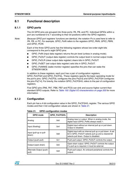
Each pin has a 4-bit configuration value in the GPIO_PxCFGH/L register. The various GPIO<br />
modes and their 4 bit configuration values are shown in Table 21.<br />
Table 21.<br />
GPIO configuration modes<br />
GPIO mode GPIO_PxCFGH/L Description<br />
Analog<br />
Input (floating)<br />
Input (pull-up or pulldown)<br />
0x0<br />
0x4<br />
0x8<br />
Analog input or output. When in analog mode, the<br />
digital input (GPIO_PxIN) always reads 1.<br />
Digital input without an internal pull up or pull down.<br />
Output is disabled.<br />
Digital input with an internal pull up or pull down. A set<br />
bit in GPIO_PxOUT selects pull up and a cleared bit<br />
selects pull down. Output is disabled.<br />
Output (push-pull) 0x1 Push-pull output. GPIO_PxOUT controls the output.<br />
Output (open-drain)<br />
Alternate Output (pushpull)<br />
0x5<br />
0x9<br />
Open-drain output. GPIO_PxOUT controls the output.<br />
If a pull up is required, it must be external.<br />
Push-pull output. An onboard peripheral controls the<br />
output.<br />
Doc ID 018587 Rev 2 56/215


