


Create successful ePaper yourself
Turn your PDF publications into a flip-book with our unique Google optimized e-Paper software.
<strong>STM32W108C8</strong><br />
General-purpose timers<br />
autoreload value down to 1 and generates a counter underflow event. Then it restarts<br />
counting from 0.<br />
In this mode, the direction bit (TIM_DIR in the TIMx_CR1 register) cannot be written. It is<br />
updated by hardware and gives the current direction of the counter.<br />
The update event can be generated at each counter overflow and at each counter<br />
underflow. Setting the TIM_UG bit in the TIMx_EGR register by software or by using the<br />
slave mode controller also generates an update event. In this case, the both the counter and<br />
the prescalar's counter restart counting from 0.<br />
Software can disable the update event by setting the TIM_UDIS bit in the TIMx_CR1<br />
register. This avoids updating the shadow registers while writing new values in the buffer<br />
registers. Then no update event occurs until the TIM_UDIS bit has been written to 0.<br />
However, the counter continues counting up and down, based on the current auto-reload<br />
value.<br />
In addition, if the TIM_URS bit in the TIMx_CR1 register is set, setting the TIM_UG bit<br />
generates an update event, but without setting the INT_TIMUIF flag. Thus no interrupt<br />
request is sent. This avoids generating both update and capture interrupt when clearing the<br />
counter on the capture event.<br />
When an update event occurs, the update flag (the INT_TIMUIF bit in the INT_TIMxFLAG<br />
register) is set (unless TIM_USR is 1) and the following registers are updated:<br />
● The prescaler shadow register is reloaded with the buffer value (contents of the<br />
TIMx_PSC register).<br />
● The auto-reload active register is updated with the buffer value (contents of the<br />
TIMx_ARR register). If the update source is a counter overflow, the auto-reload is<br />
updated before the counter is reloaded, so that the next period is the expected one.<br />
The counter is loaded with the new value.<br />
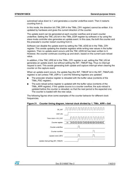
The following figures show some examples of the counter behavior for different clock<br />
frequencies.<br />
Figure 21.<br />
Counter timing diagram, internal clock divided by 1, TIMx_ARR = 0x6<br />
Doc ID 018587 Rev 2 116/215


