DILA Tech Guide.qxd - BigScreen.se
DILA Tech Guide.qxd - BigScreen.se
DILA Tech Guide.qxd - BigScreen.se

You also want an ePaper? Increase the reach of your titles
YUMPU automatically turns print PDFs into web optimized ePapers that Google loves.
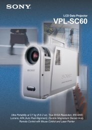
Figure 4: Basic Structure of D-ILA TM Projector<br />
Video<br />
signal<br />
D-ILA device<br />
PBS<br />
Light<br />
collecting lens<br />
Projection lens<br />
Figure 4 shows how a D-ILA TM projector operates. The natural light<br />
from the light source is <strong>se</strong>parated by the PBS (polarized beam splitter)<br />
into a P wave component (light vibrating parallel to the surface)<br />
and an S wave component (light vibrating perpendicular to the surface.)<br />
The P wave component proceeds straight through the PBS.<br />
Since it is unnecessary light, it is not u<strong>se</strong>d. Only the S wave component<br />
reaches the D-ILA TM elements. The light that has reached<br />
the elements pas<strong>se</strong>s through the liquid crystal layer, is reflected by<br />
the pixel electrodes, pas<strong>se</strong>s through the liquid crystal layer again,<br />
and reaches the PBS. At this time, the component that was modulated<br />
in the liquid crystal layer is converted into P waves and after it<br />
has pas<strong>se</strong>d through the PBS, is projected onto the screen through<br />
the projection lens. On the other hand, the S wave component that<br />
was not modulated is reflected by the PBS and returns to the light<br />
source, so it does not contribute to the projection image.<br />
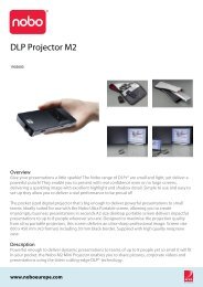
Figure 5 shows the optic modulation characteristics for the vertically<br />
oriented liquid crystal. (a) is for when there is no modulation and<br />
(b) is for when there is modulation. When the input signal to the<br />
device is black, voltage is not applied to the pixel electrode, the<br />
liquid crystal layer remains in its vertical orientation (as shown in the<br />
diagram), the light axis of S wave and liquid crystal long axis are<br />
parallel, and optic modulation does not take place in the liquid crystal<br />
layer. The light input, as S waves, is output as it is (without<br />
modulation) and reflected by the PBS. As a result, this light does<br />
not reach the screen and it reproduces the black state. The high<br />
contrast characteristic of the vertically oriented liquid crystal is for<br />
black reproduction, when the liquid crystal is not modulated. This<br />
is how true black is obtained. (b) shows the state in which voltage<br />
is applied to the pixel electrode. Since the liquid crystal is the n<br />
type, the long axis tilts in the direction perpendicular to the applied<br />
electric field. At this time, the axis of the incoming S wave light and<br />
the long axis of the liquid crystal inter<strong>se</strong>ct. Due to the compound<br />
refraction of the liquid crystal, the light is converted into elliptically<br />
polarized light and circularly polarized light, a P wave component is<br />
generated, and the projected optical image is formed on the<br />
screen. The maximum modulation of the liquid crystal occurs when<br />
all the S waves coming into the device are converted into P waves<br />
to reproduce a white image.<br />
Figure 5: Modulation Characteristic of Vertically<br />
Oriented Liquid Crystal<br />
When not modulated<br />
(a)<br />
When modulated<br />
(b)<br />
Features of D-ILA TM<br />
The features of D-ILA TM are as shown in Table 2. Becau<strong>se</strong> of the<br />
high aperture ratio, any ri<strong>se</strong> in the temperature of the device due to<br />
photothermal conversion and any malfunctioning of drive elements<br />
due to photoelectric conversion is minimal. Therefore, it is possible<br />
to handle high intensity light. Moreover, the resolution is determined<br />
by the CMOS process scaling, as discus<strong>se</strong>d above. So pixel pitches<br />
of only a few microns are possible and, as mentioned previously, the<br />
pixels for full HDTV (1,920 x 1,080 pixels) can fit onto a CMOS board<br />
less than 1 inch across. Also, the vertical orientation of the liquid<br />
crystal is fully utilized. The high light output, high resolution, and high<br />
contrast of the conventional ILA TM are retained, while shape, weight,<br />
and cost issues of the ILA TM are resolved by converting the writing<br />
method from an optical image to direct writing with electrical signals.<br />
Table 2: D-ILA TM Projector Features<br />
High resolution<br />
High aperture ratio<br />
High light output<br />
High contrast<br />
High-speed<br />
respon<strong>se</strong><br />
Compact, lightweight<br />
Currently, this is the element with the highest<br />
possible density. When pixel size is the<br />
same, it provides the highest resolution;<br />
when resolution is the same, it has the smallest<br />
pixel size.<br />
As long as the insulation between pixel electrodes<br />
is maintained, the size of the nonopening<br />
<strong>se</strong>ction can be minimized, so resolution<br />
can be rai<strong>se</strong>d with only a minimal<br />
reduction in the aperture ratio.<br />
The aperture ratio and light output are proportional<br />
and the non-opening <strong>se</strong>ction is<br />
small. As a result, photothermal conversion is<br />
minimal, the light withstand level for the elements<br />
is high, and powerful light sources can<br />
be u<strong>se</strong>d.<br />
The vertically oriented crystal provides a nomodulation<br />
state, so the highest contrast of<br />
a few thousand to one can be attained for<br />
the element alone.<br />
With the reflective type, light is modulated<br />
while it goes back and forth. As a result, the<br />
thickness of the liquid crystal layer is half that<br />
of the transmissive type, the electric field<br />
boundary strength gw is double, and highspeed<br />
respon<strong>se</strong> is possible.<br />
The high pixel density and high aperture ratio<br />
allows the elements to be light and compact.<br />
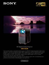
Development of color projectors<br />
Figure 6 shows the configuration of a three-D-ILA TM projector. The<br />
first and <strong>se</strong>cond “fly-eye” lens plates and the PS composite plates<br />
sandwiched between them convert the natural white light of the light<br />
source into S wave. This rai<strong>se</strong>s the operating efficiency of the light<br />
source and improves the uniformity of the amount of light on the<br />
screen at the same time. Sub<strong>se</strong>quently, the light is <strong>se</strong>parated into<br />
RGB (red, green, blue) components through color photospectrometry<br />
and each color is input to the corresponding PBS. The S wave<br />
component, reflected by the PBS, becomes the P wave component<br />
modulated by the liquid crystal as shown in Figure 4 and discus<strong>se</strong>d<br />
above. Only this component pas<strong>se</strong>s through the PBS, while the RGB<br />
is synthesized by the cross-dichroic prism, and projected onto the<br />
screen as a color image through the projection lens.<br />
The three-panel projector is the most fundamental method for handling<br />
color. This is a system in which the light utilization efficiency is<br />
high and projector performance, color reproduction, contrast, and<br />
6